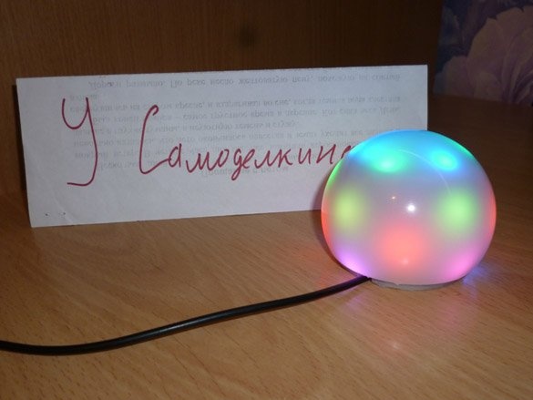
Good day or night, anyone like that. Today I will share instructions on how to make a small nightlight. The basis is a matte diffuser from a burnt out LED bulb. And inside we put Arduino Pro Mini and SW2812 LEDs. I will post only one sketch, but there can be many options for colors or transfusions. Let's start, as always, with the list of necessary:
- Diffuser from LED lamp, E27 base
- 5V power supply
- Arduino Pro Mini 5V
- USB-TTL (for uploading a sketch to arduino)
- WS2812 LEDs
- Thin plastic
- Double sided tape
- Charging from the phone is not necessary, but working
- soldering iron
- wires
- Solder, rosin
- Hot glue gun
Step 1. Making the case.
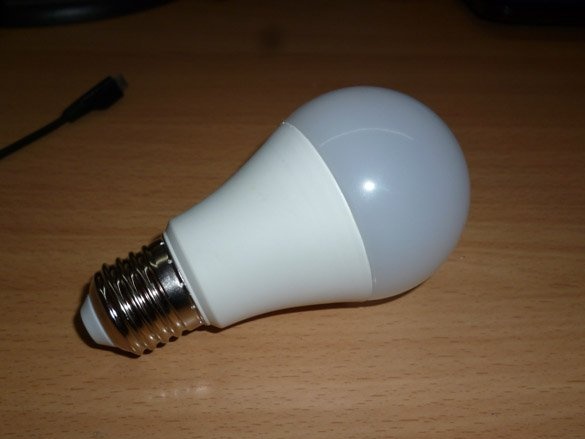
For starters, we need to get a diffuser. We take the LED bulb with the E27 base. It’s better, of course, to take a bulb that has already worked out:
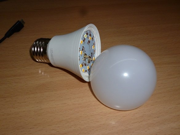
With one hand we hold the bulb by the base and the plastic case, with the other we take it by the diffuser and break the bulb. The diffuser should easily move away from the body, as it rests only on the sealant:
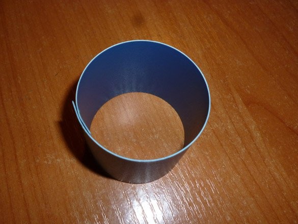
Now we need to make a base to which we will stick the LEDs. To do this, take a thin plastic, a cover from a plastic folder is suitable. Now we measure the inner diameter of the landing hole of the diffuser, and we also need to measure the depth of the diffuser. We proceed to the manufacture of the basics. It will be in the form of a cylinder, the diameter of which should be 5 mm less than the inner diameter of the bore of the diffuser. And the height is 7 mm less than the depth of the diffuser. It should look something like this:
Next, we make and glue to the cylinder a cover cut out of the same plastic:
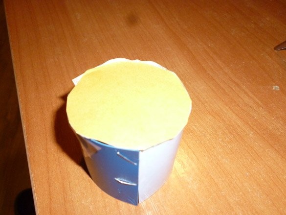
This is where we finish.
Step 2. Electrics.
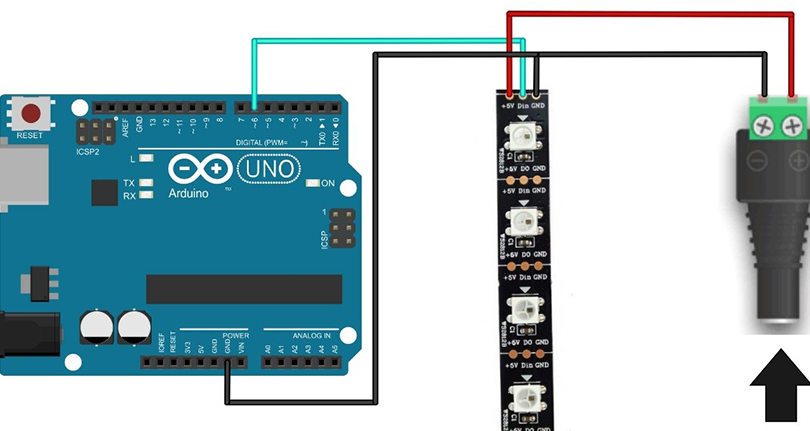
As I said earlier, the controller will be the Arduino Pro Mini, a version that runs on 5 volts. The LED strip is connected quite simply, for this you need to connect the + 5V contact to the plus from the 5 volt power supply, and GND to the minus. DIN pin (input) connect to pin 6 of the Arduino. The tape connection port can be changed to any convenient in the sketch. Arduino will be powered by the same power supply. Since we will use a stabilized power supply, we connect the plus from the power supply to the 5V pin on the Arduino. The minus power supply must be connected to the GND Arduino. The scheme is as follows:
So, one LED, at maximum brightness of all three colors, consumes 60 mA. I fit 25, so it turns out:
25 x 60 mA = 1500 mA = 1.5 A
That is, I need a 5 V, 1.5 A power supply.This is the maximum current strength that will be when all the LEDs are turned on in the maximum brightness mode of all three colors.
If you are interested, you can read all the specifications in the datasheet:
View online file:
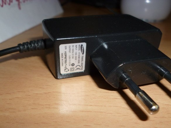
As the power supply, we take the old charging from the phone. The power supply must be selected at 5 volts, and in terms of power, calculate how many LEDs you fit:
We cut off the plug from it and solder the wires directly to the tape, do not forget to check the polarity with a tester or multimeter. You should also draw wire leads to power the Arduino. And the signal wire from the tape to the Arduino.
At the bottom of the cylinder we make a slot in order to skip the contacts of the tape with the soldered wires inside:
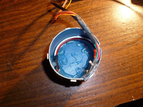
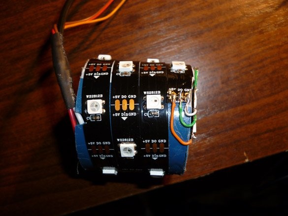
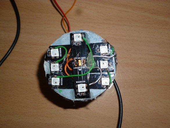
I inserted the end of the tape with wires into the slot, we fix it with hot glue. Next, glue the Lena in a circle, slightly lift it up so that a spiral of tape is obtained. We also glue the tape to the top of the cylinder, the number of diodes depends on the diameter, I have a maximum of two LEDs placed diagonally on the top, and so the contacts hang down:
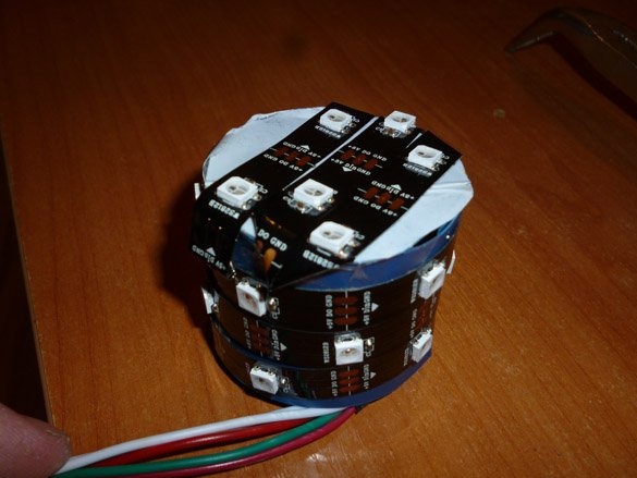
If you did the same, don’t be upset, just cut the tape hanging around the edges and solder the wires directly to the LEDs. Contact WS2812:
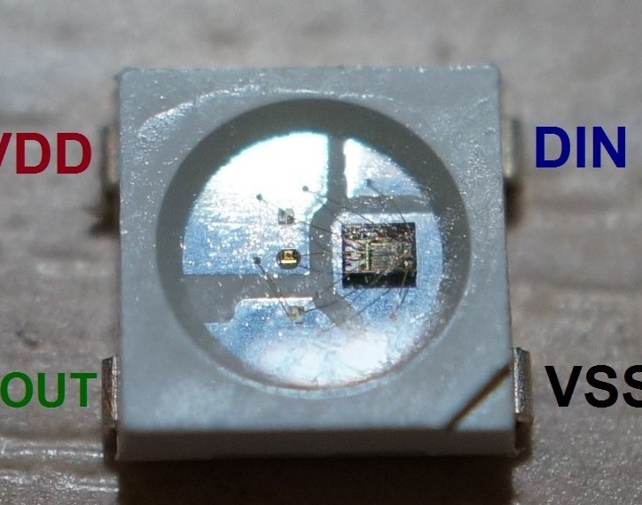
Pay attention, the LED strip on the WS2812B has a direction, on the one hand (beginning or input) it has DIN, + 5V, GND contacts. And on the other hand (end or exit) DO, + 5V, GND. If you solder directly to the LEDs, look at the location of the contacts, focusing on the key (corner cut). To simplify installation, arrows are drawn on the tape indicating the direction. Pay special attention to the transition to the top, it turns out a very sharp bend, it is likely to break the tape. I got it like this:
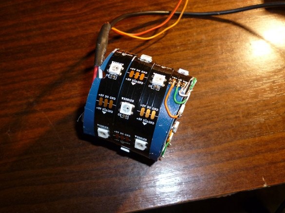
From above, it was soldered directly to the LEDs:
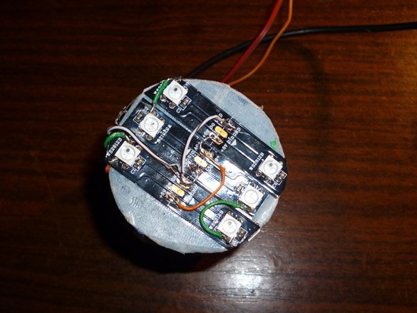
And in the middle, a second level, a couple more LEDs:
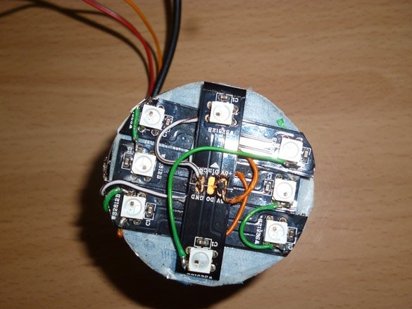
And for reliability, fill the wires with hot glue:
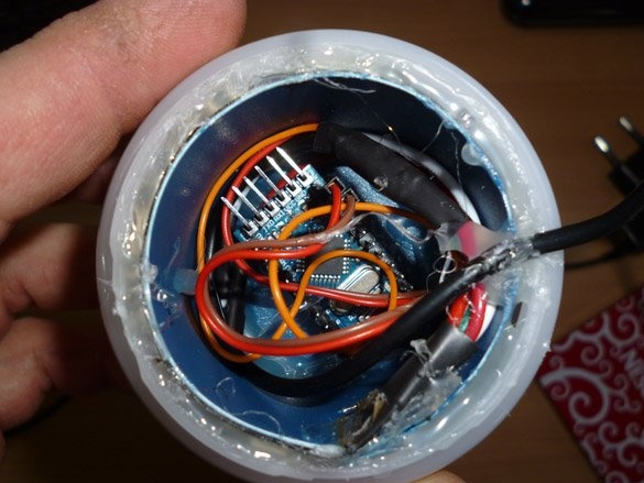
Now we insert our cylinder with LEDs inside the ball from the bulb. Using hot-melt adhesive, we fix the cylinder inside the ball in a circle:
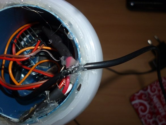
Do not forget to make a slot to output the power wire:
Step 3. Preparing the environment and firmware.
To download the sketch (or firmware) we will use the Arduino IDE. Download the latest version from the official and install it.
Next, you need to add the library for working with WS2812 from Adafruit NeoPixel-master:
To do this, first download the archive. Then unpack this archive. And we move the unpacked files to the “libraries” folder, which is located in the folder with the Arduino IDE installed. Can be made easier. Launch the Arduino IDE. Do not unpack the downloaded archive. Right in the Arduino IDE, select the menu item Sketch - Connect Library. At the very top of the drop-down list, select the "Add .Zip library" item. A dialog box should appear. Next, we select our library, Adafruit_NeoPixel-master. A little worth the wait. Again, open the menu item Sketch - Connect Library. Now at the very bottom of the drop-down list you will see a new library. By restarting the Arduino IDE, the library can be used.
Download my sketch:
It remains to fill the sketch in Arduino. We use the Arduino Pro Mini. This version of the popular Arduino does not have a USB-TTL chip soldered on the board. Therefore, to communicate with the computer and upload the sketch, you must use a separate USB-TTL. Connection as follows:
Arduino - USB-TTL
RX (P0) - TX
TX (P1) - RX
GND - GND
USB-TTL power will be from the computer's USB port. Arduino can be powered from USB-TLL or use an external power source. The main thing is that the GND USB-TTL pin and the Arduino are connected. Most often, USB-TTL without a DTR pin is on sale. The DTR pin must be connected to the Reset Arduino in order to automatically reboot before loading the sketch. If you, like mine, do not have this conclusion, you must manually reboot before uploading the sketch. We act like this: we connect everything according to the scheme described above, open the Arduino IDE, open the sketch you downloaded, click the button - Download - and see what is written below. While the “compilation” is in progress, we are not doing anything, we are just waiting for the “loading” message to appear, we need to press the Reset button on the Arduino.If it is not convenient to press a button on the board, you can display a button connected to GND and Reset. Or just bring the wires to the same conclusions and close them at the right time.
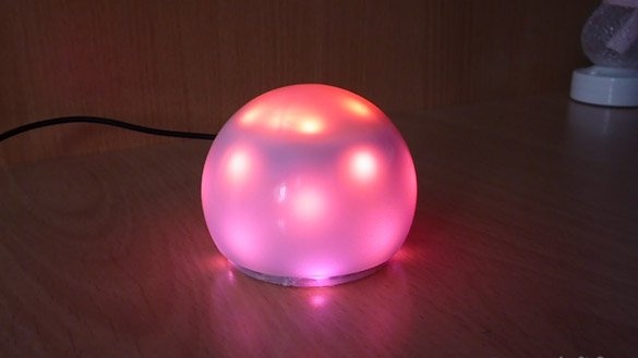
I want to say that there are a lot of options for lighting the night light, I wrote only a few in the sketch that I myself liked. You can edit the sketch as you like. Experiment and choose what you like best.