
The author of this homemade teach you how to make an 8-channel amplifier for a computer or audio system with separate analog outputs. He uses it for his desktop computer to watch movies, listen to HD music and play games.
The circuit is based on TDA2002 and TDA 2003 amplifiers with a power of 8 W and 10 W, respectively, the latter for a subwoofer.
Step 1: Materials
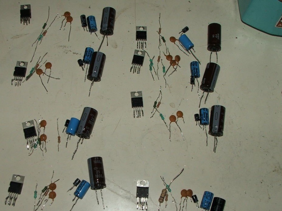
The following components will be required:
Power Amplifier: 7x TDA2002, 1x TDA2003
8 220 ohm resistors
8 resistors 22 ohms
8 resistors 1 ohm
16 capacitors of 100 nF each
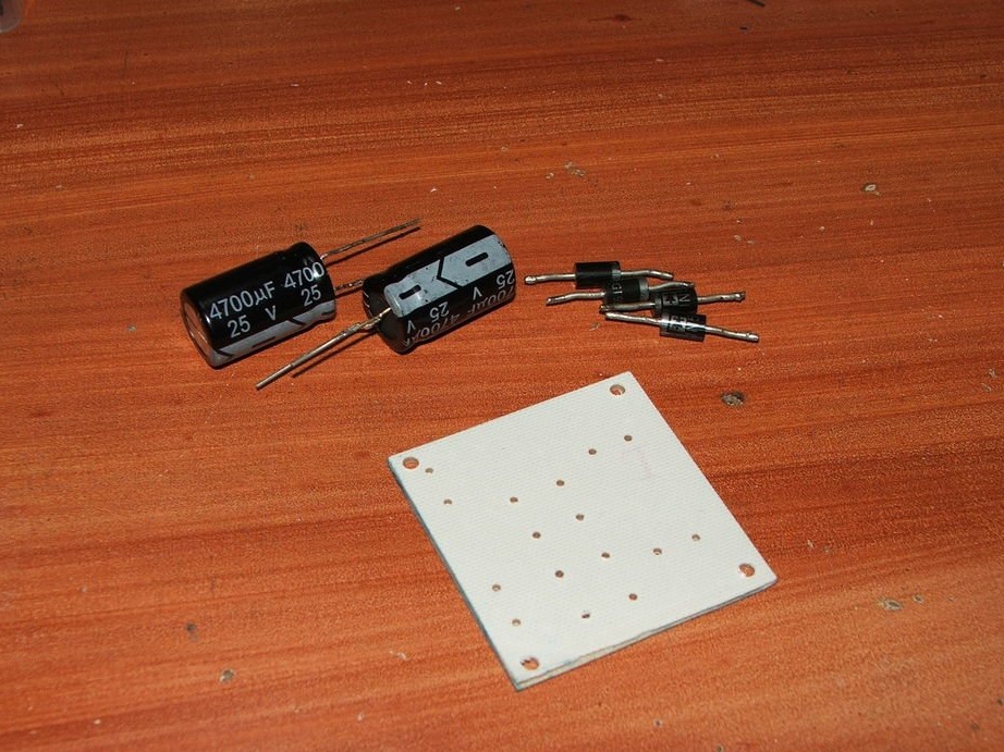
8 electrolytic capacitors 10 μF 25 V
8 electrolytic capacitors 470 μF 25 V
8 electrolytic capacitors 1000 uF 25 V
Circuit board template
net board 10 mm x 15 mm
aluminum radiators
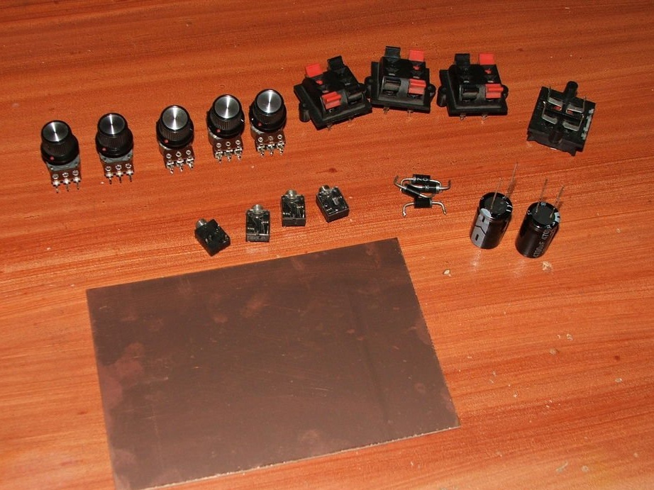
Volume control
3 stereo variable resistors 10 kOhm
2 mono variable resistors 10 kOhm
entrance and exit
4 stereo jacks
4 dual speaker terminals
6 resistors 22 kOhm
Other
speaker wire
wires for communication circuits
fuse
bottom switch
etc.
Instruments:
soldering iron
welding
tweezers
drill
permanent marker
isopropyl alcohol
vapor protection mask
plastic transparent sheet
PCB Drills
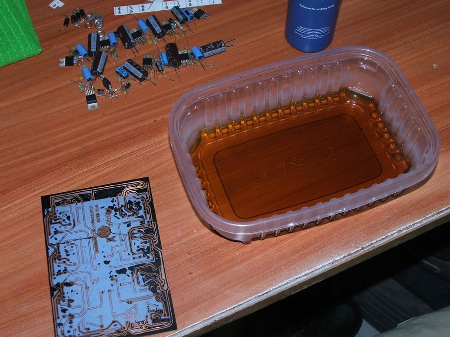
Step 2: PCB Fabrication
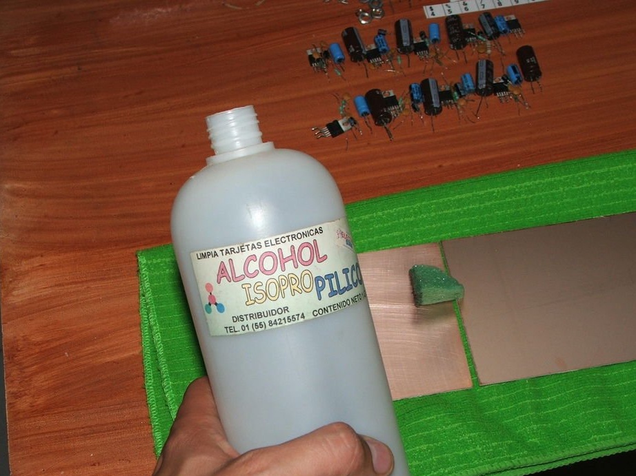
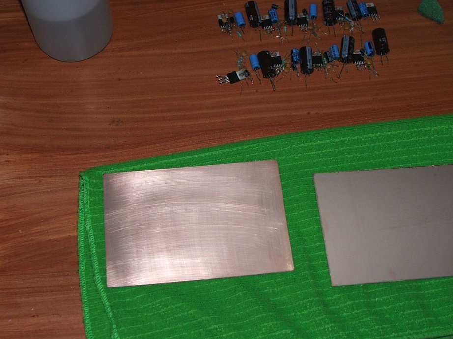
We clean the board with isopropyl alcohol to remove grease and dirt.
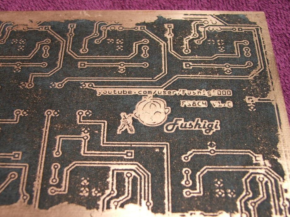
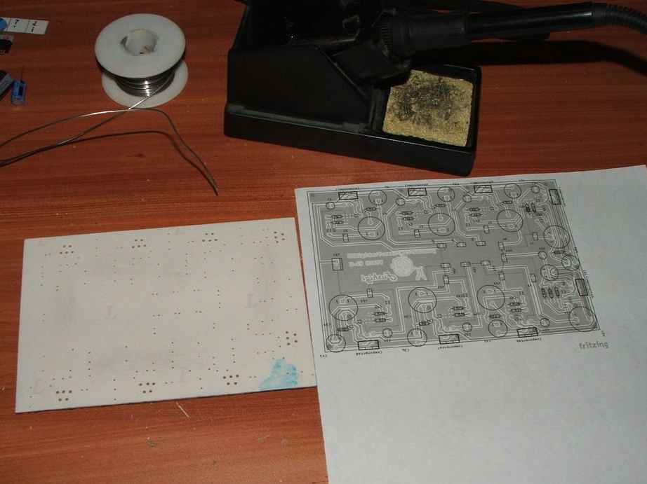
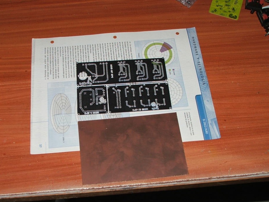
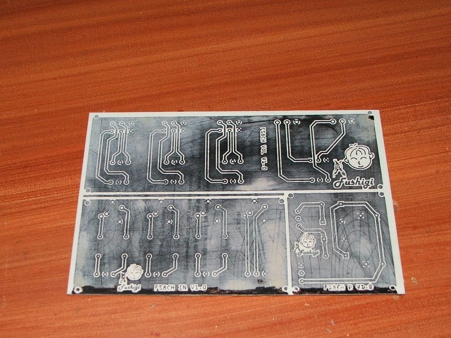
Step 3: Transfer the radio elements from the layout to the circuit board
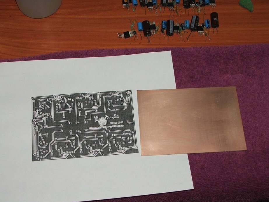
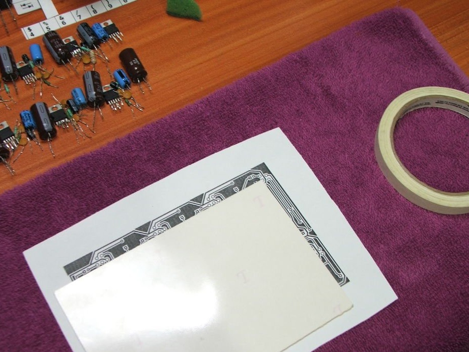
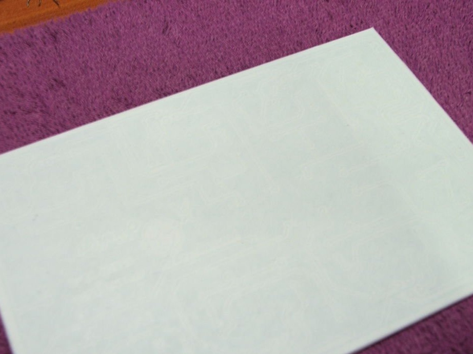
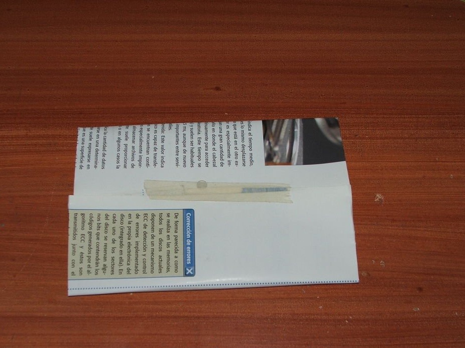
Print the chart on glossy paper, it can be special carbon paper, magazine paper or other media.
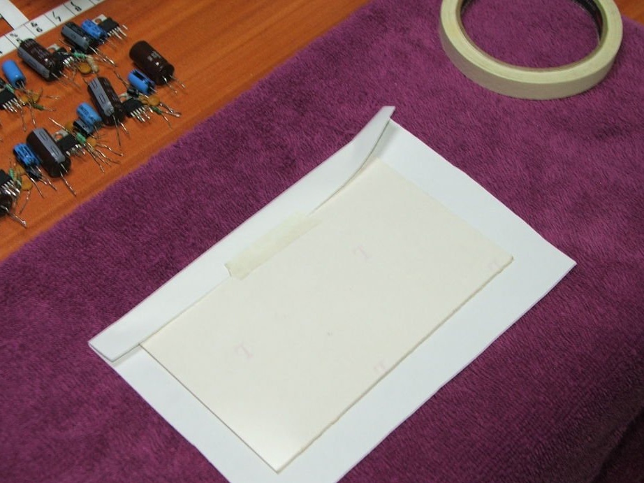
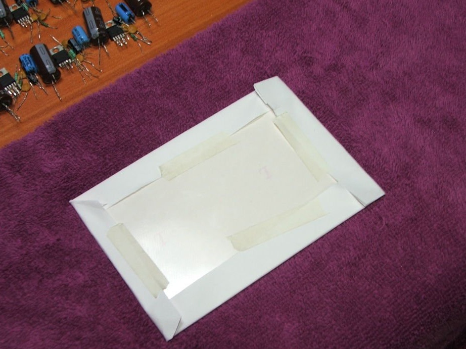
Trim the edges and glue them with the appropriate tape.
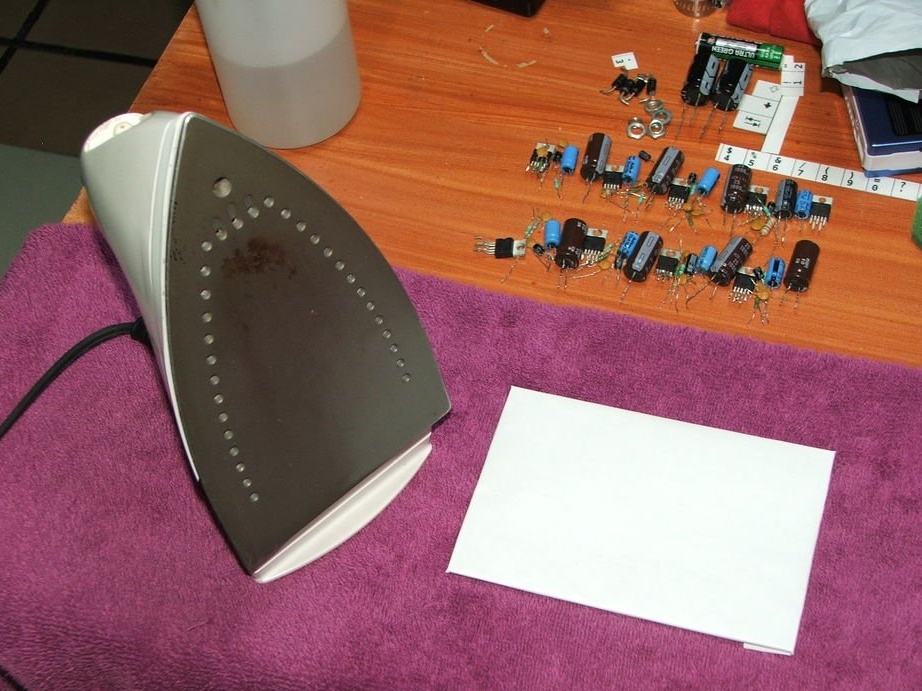
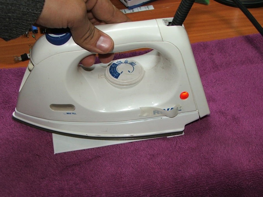
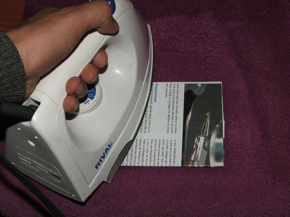
We warm the iron to the maximum and warm it from 5 to 10 minutes.
Attachments
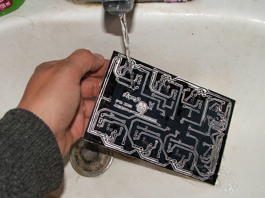
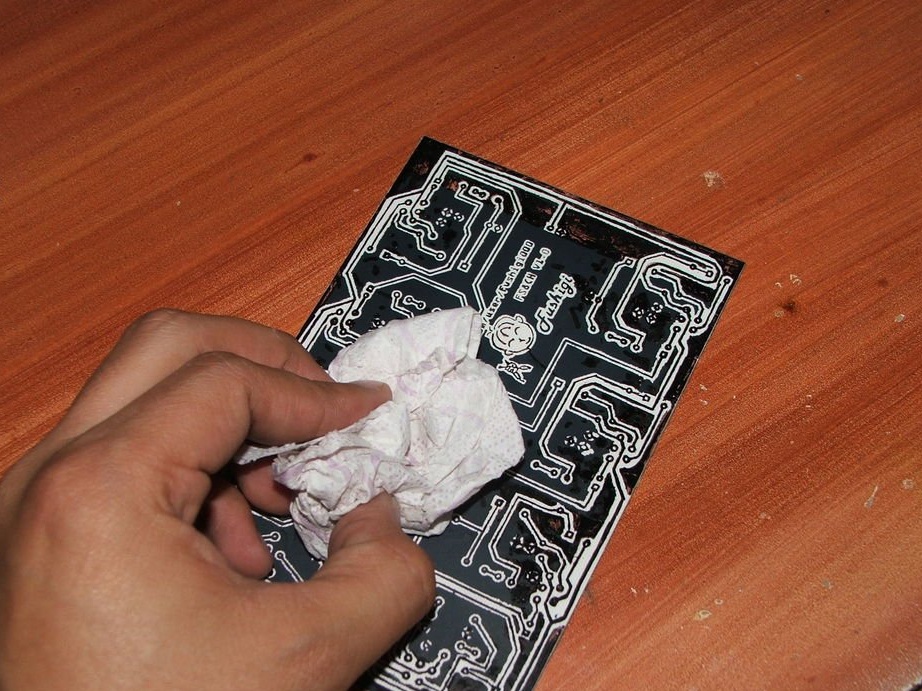
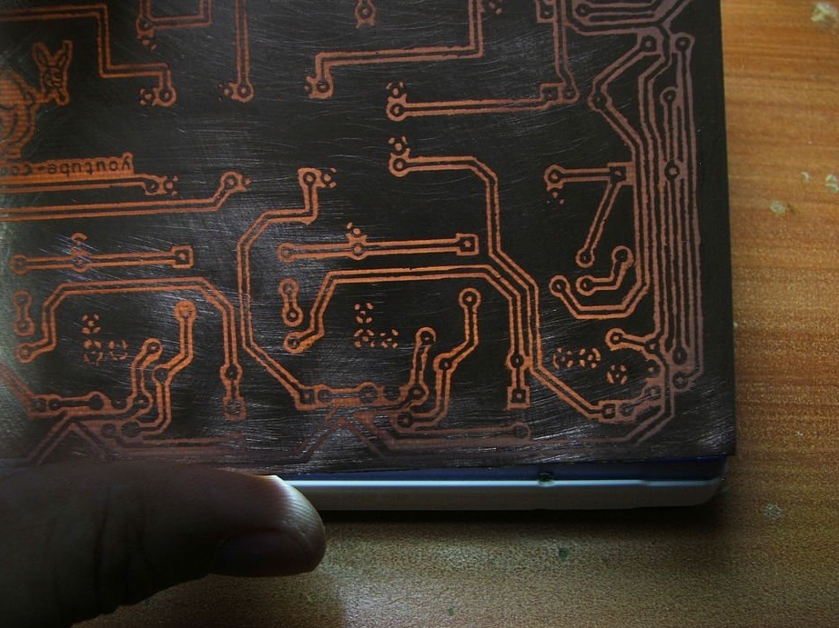
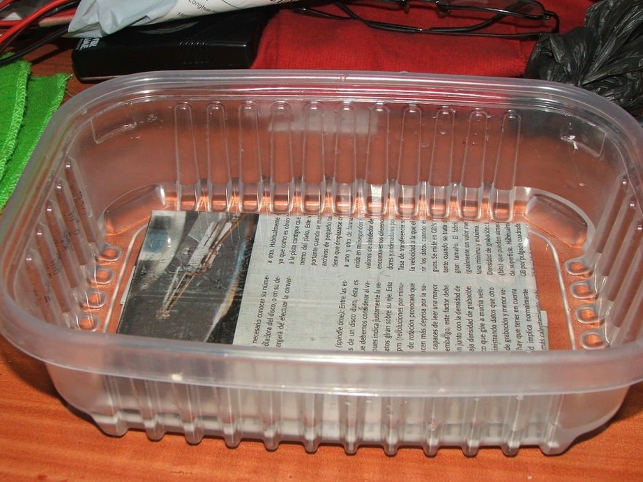
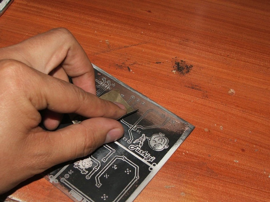
Step 4: Removing Paper
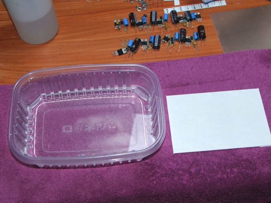
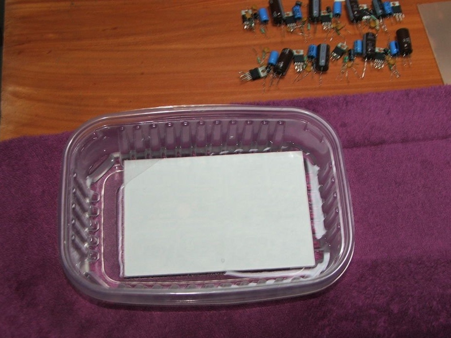
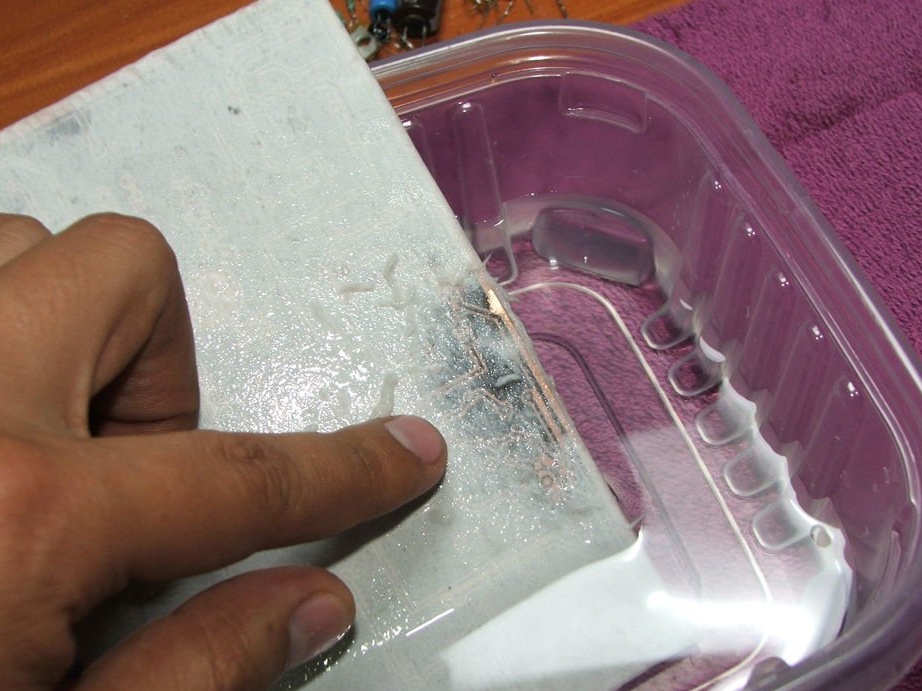
Immerse the board in water. After a few minutes, clean the paper until it is completely removed.
NOTE. If the toner is worn out, the tracks should be tinted with a permanent marker.
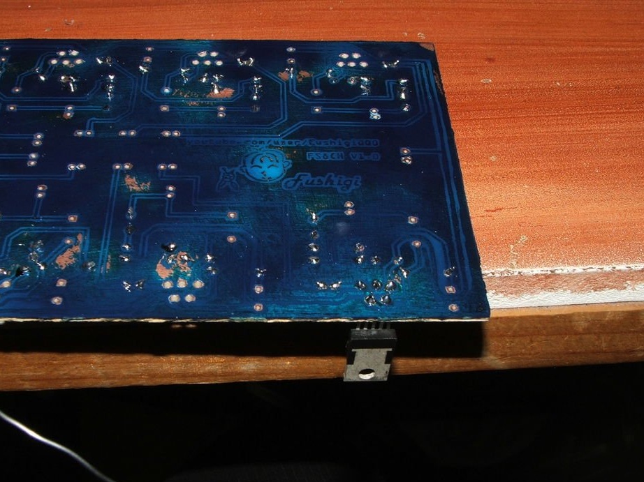
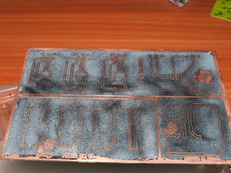
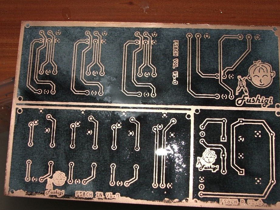
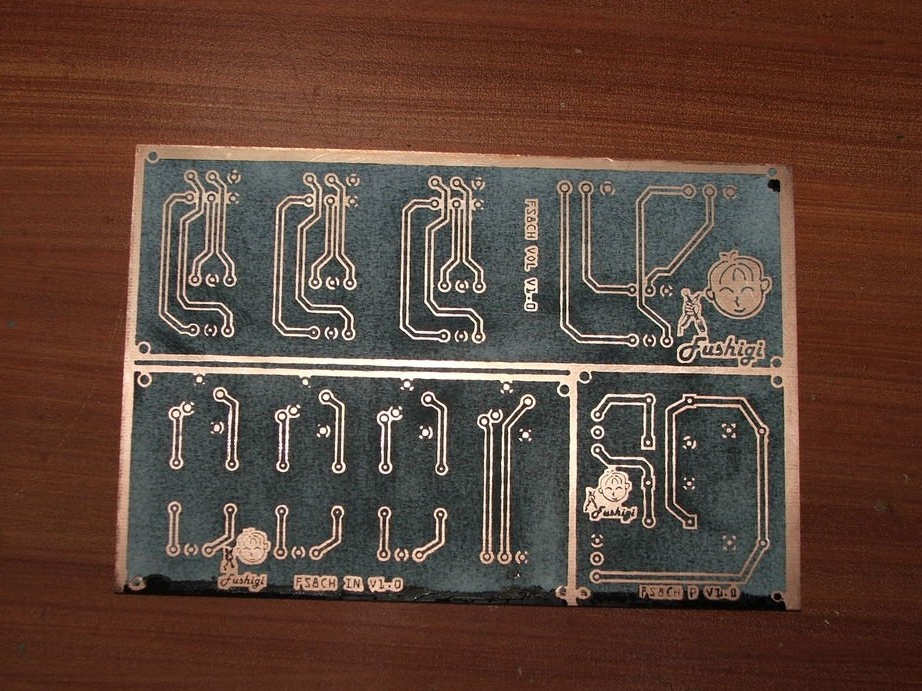
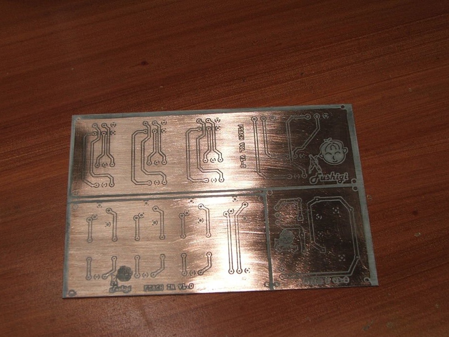
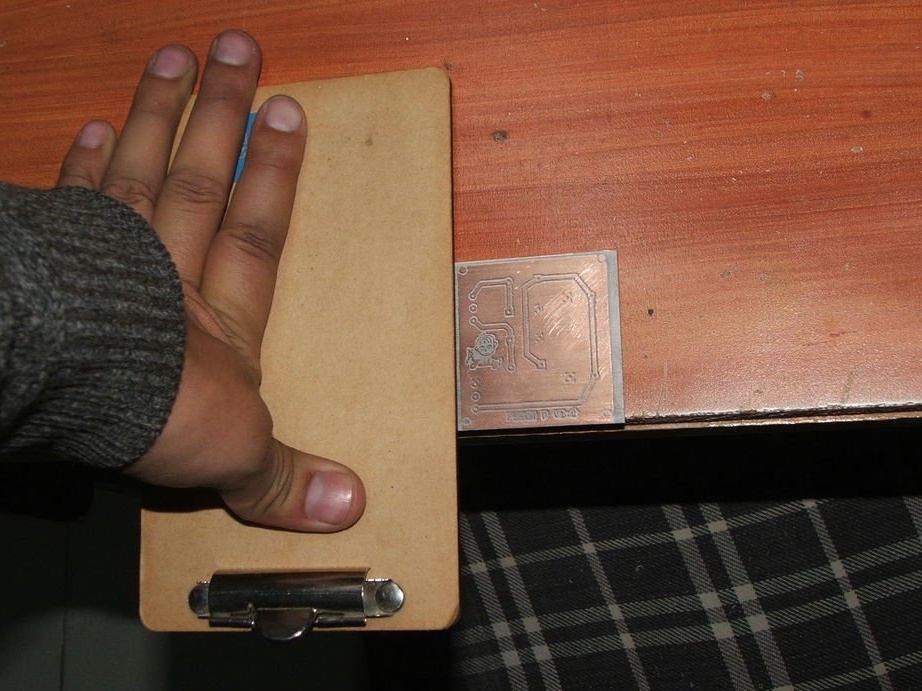
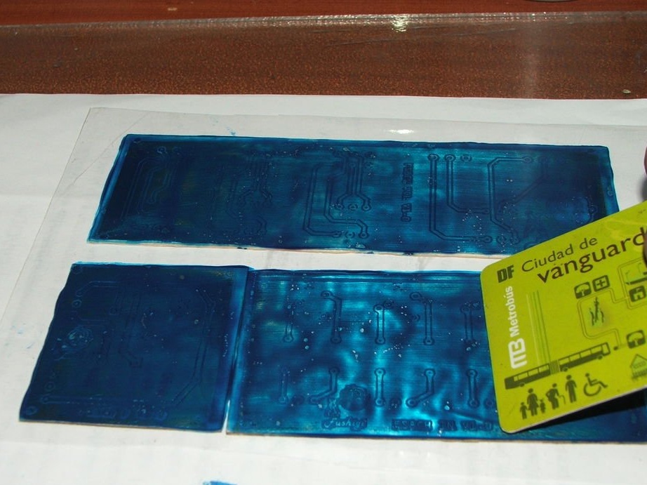
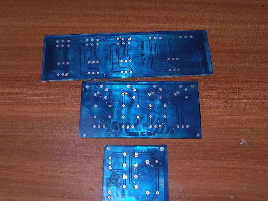
Step 5: etching the board
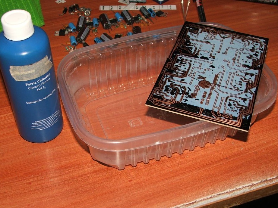
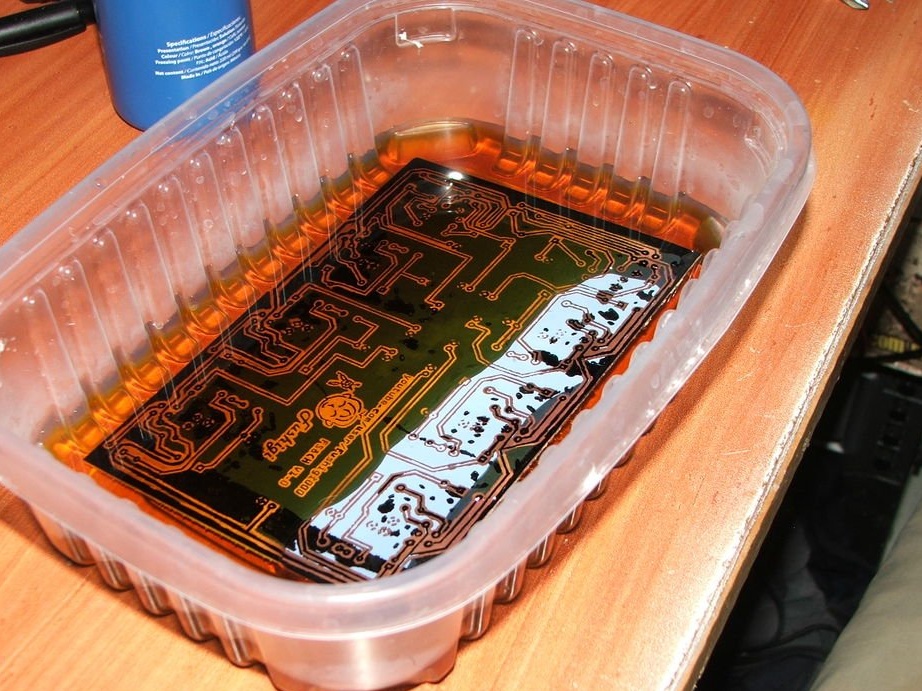
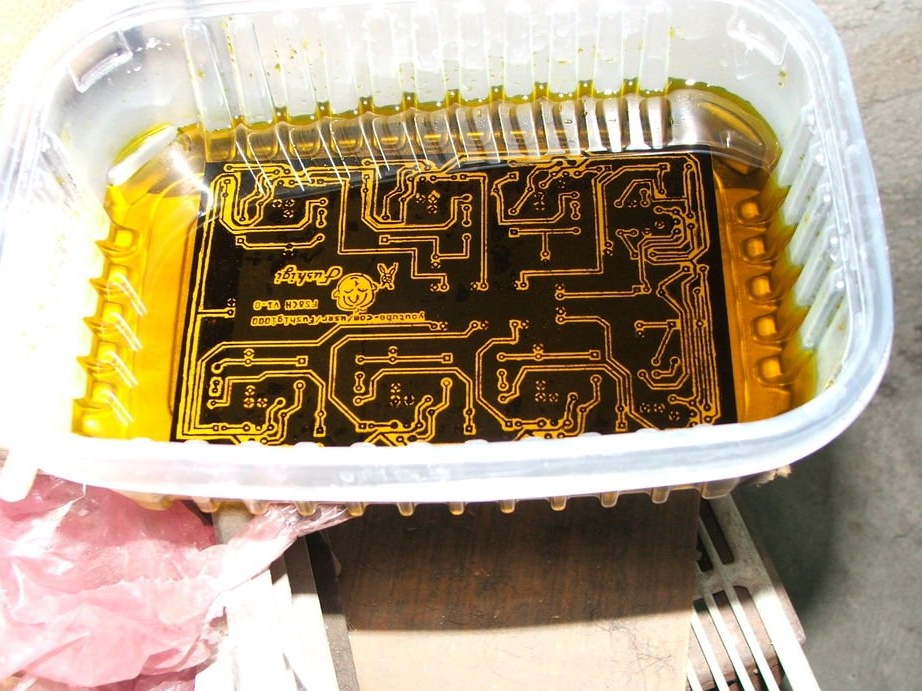
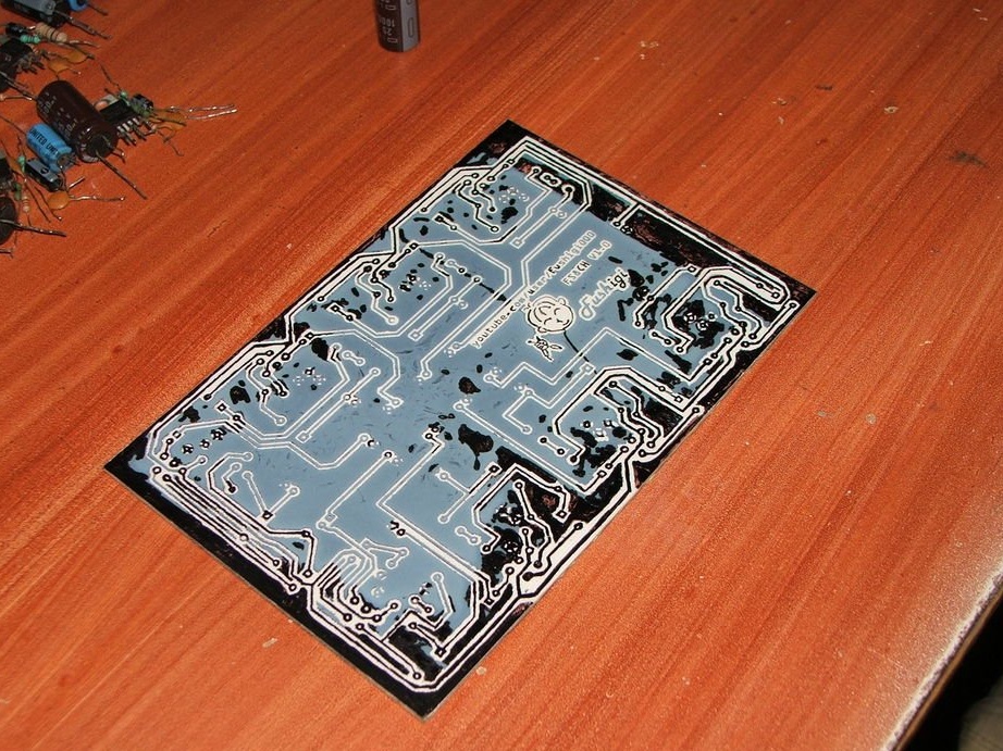
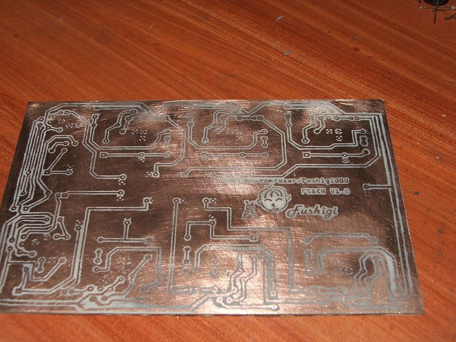
Prepare the ferric chloride according to the directions on the bottle, immerse the plate in ferric chloride and carefully move until the copper is removed.
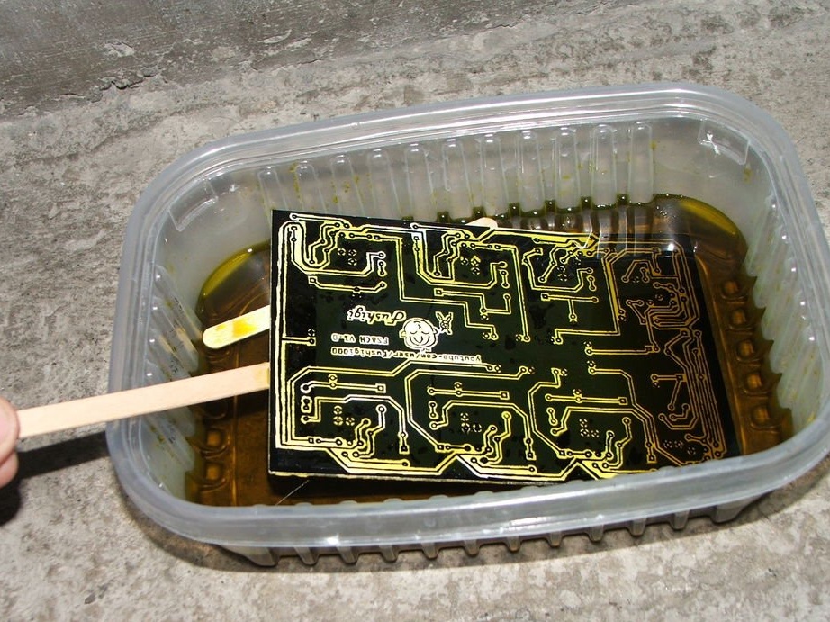
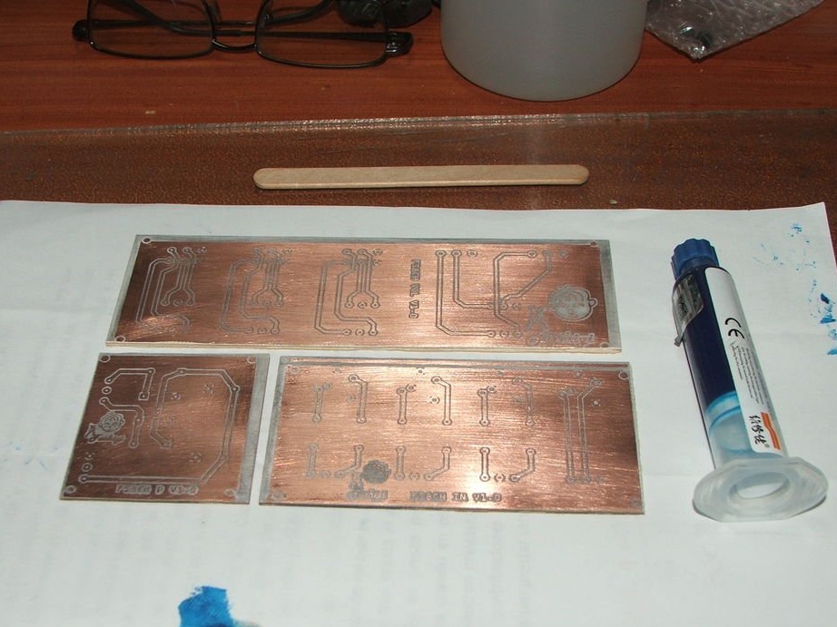
Remove ferric chloride with a wooden stick.
Then you should wash the board with water and dry with kitchen paper.
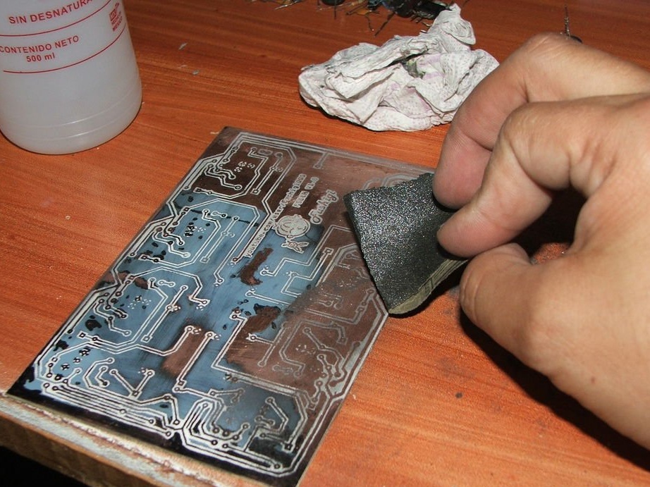
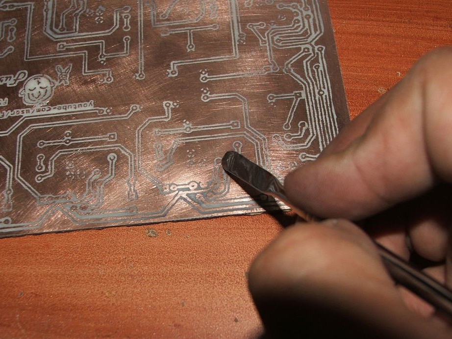
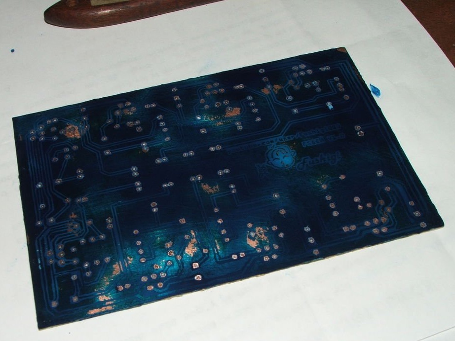
Remove toner with fine sandpaper and clean with isopropyl alcohol.
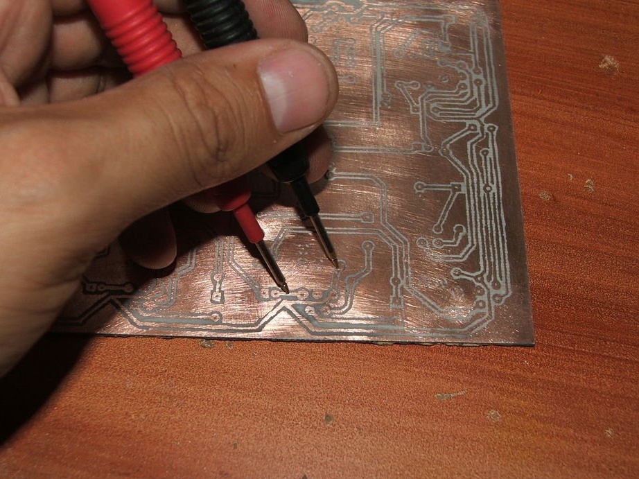
Check with a multimeter for possible short circuits if they were eliminated with a cutter or screwdriver.
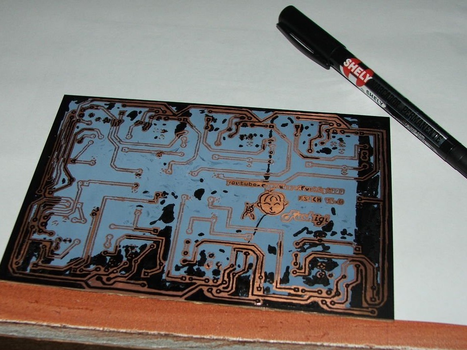
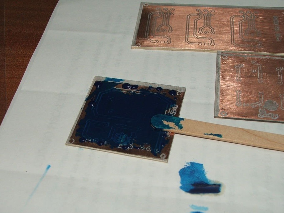
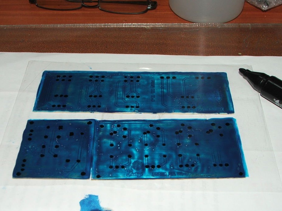
Step 6: Solder Mask
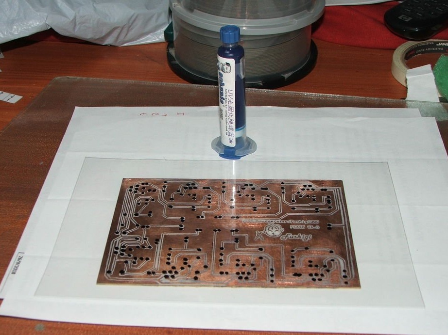
Print or draw in permanent marker pads in acetate.
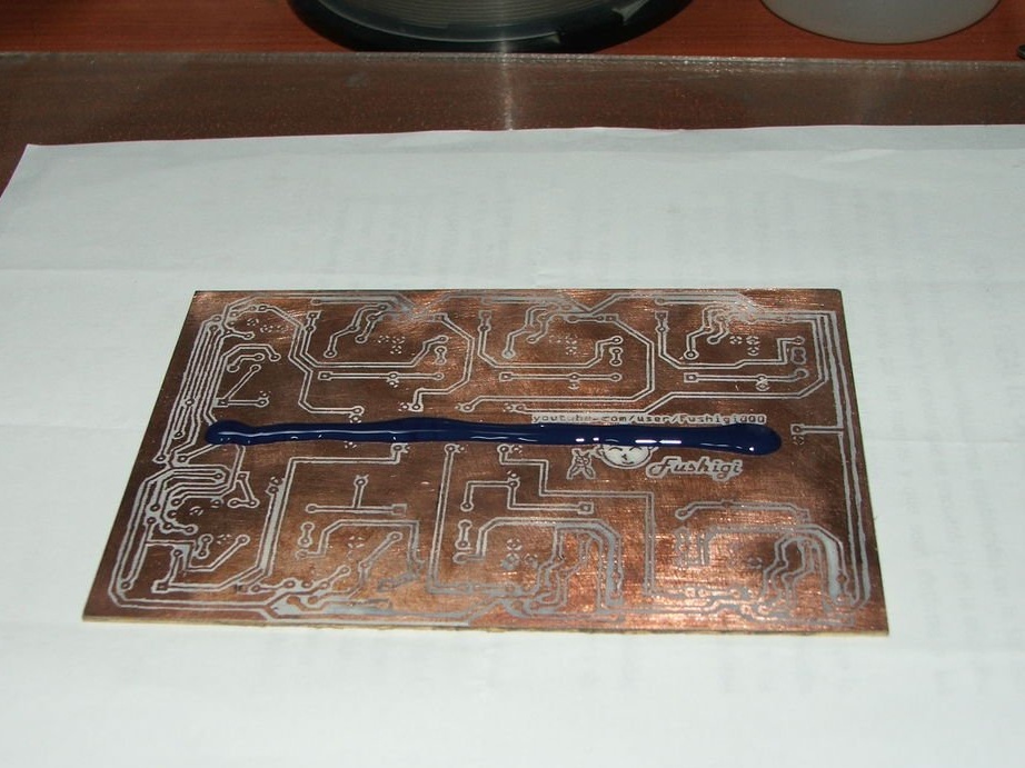
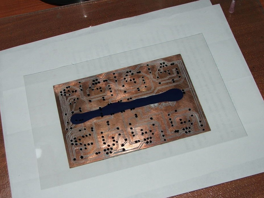
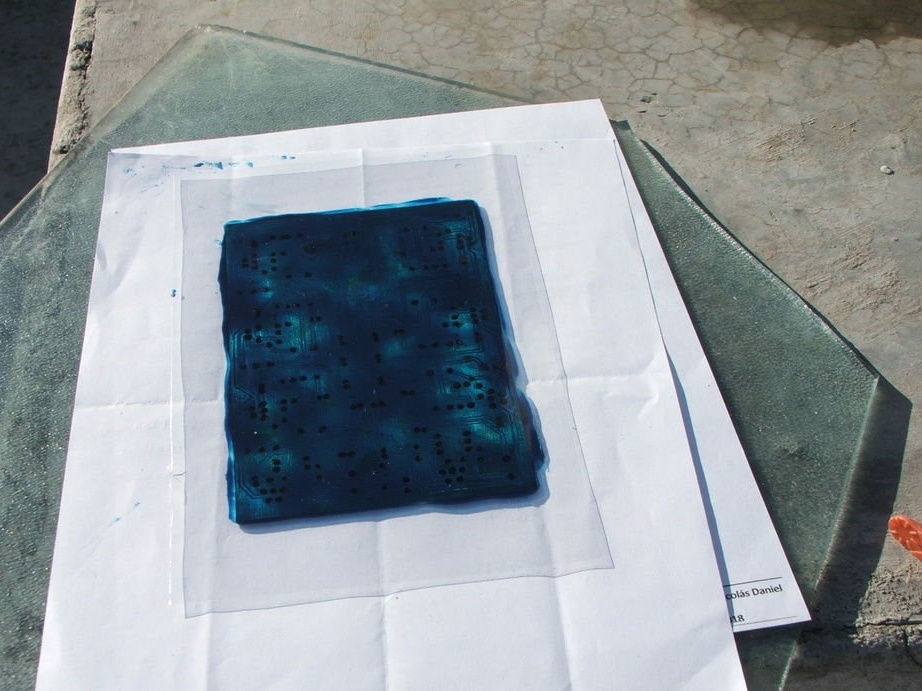
Place the solder mask on the circuit board and distribute it on the circuit board with a wooden stick. Cover the board with plastic sheet.
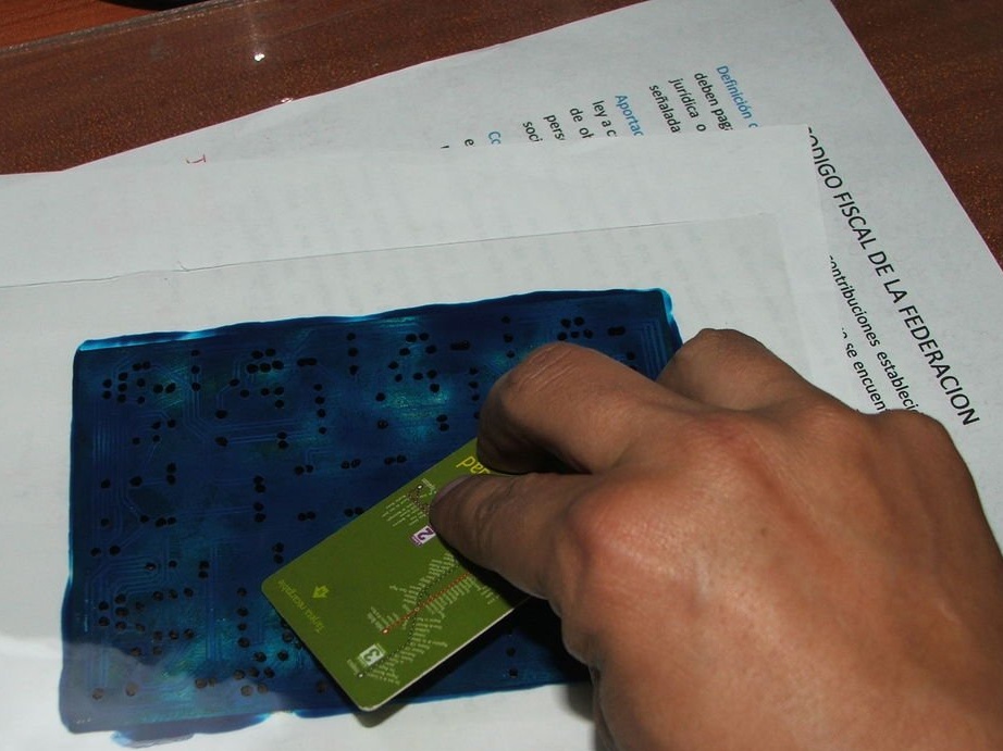
Distribute ink with a card.
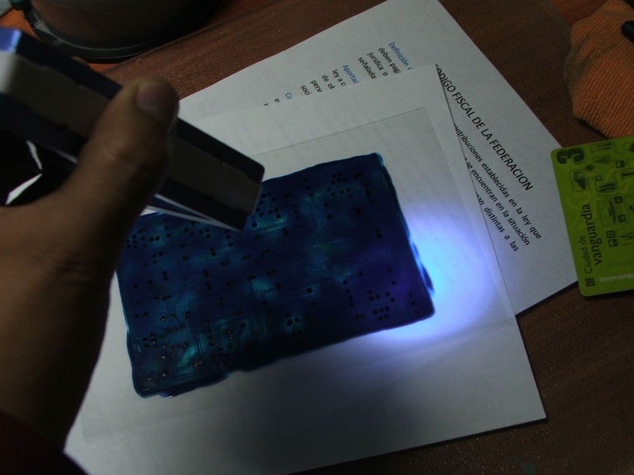
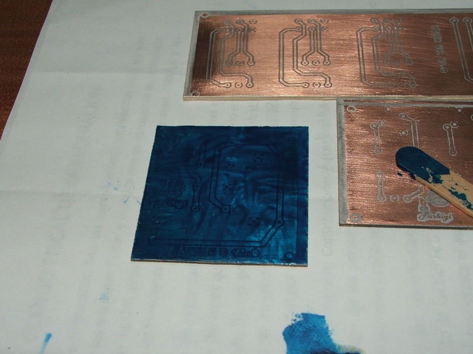
Then the board must be irradiated with a UV lamp or the sun for 5-10 minutes.
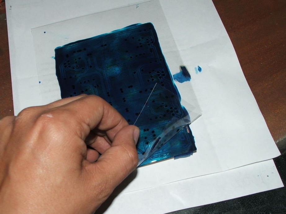
Remove plastic and clean with alcohol, acetone or thinner.
Attachments
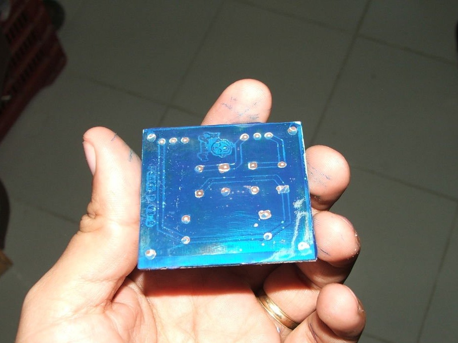
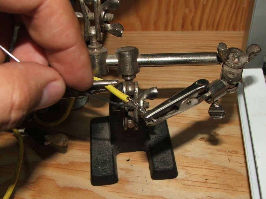
Step 7: Drill and Solder
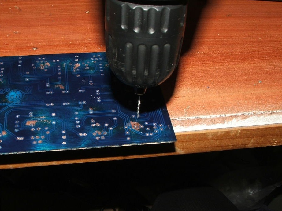
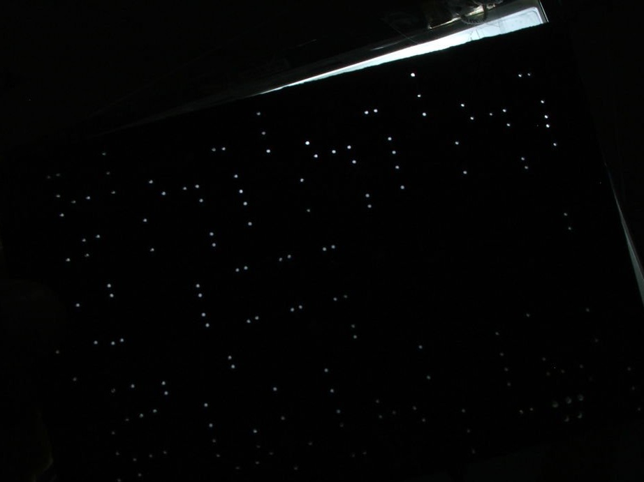
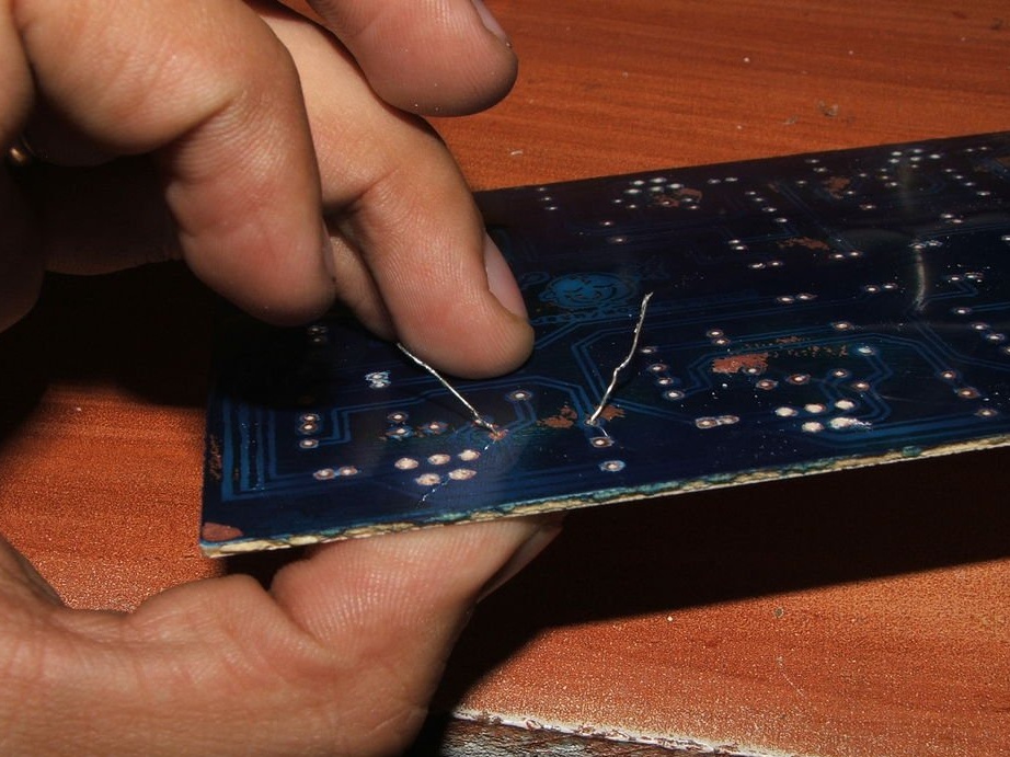
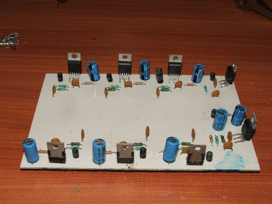
Using a drill and screwdriver, drill holes using the component template. You can use the backlight to check for holes. Remember to use the appropriate bits for each component.
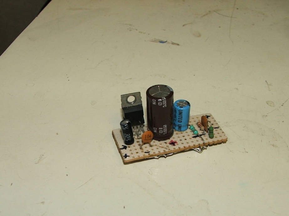
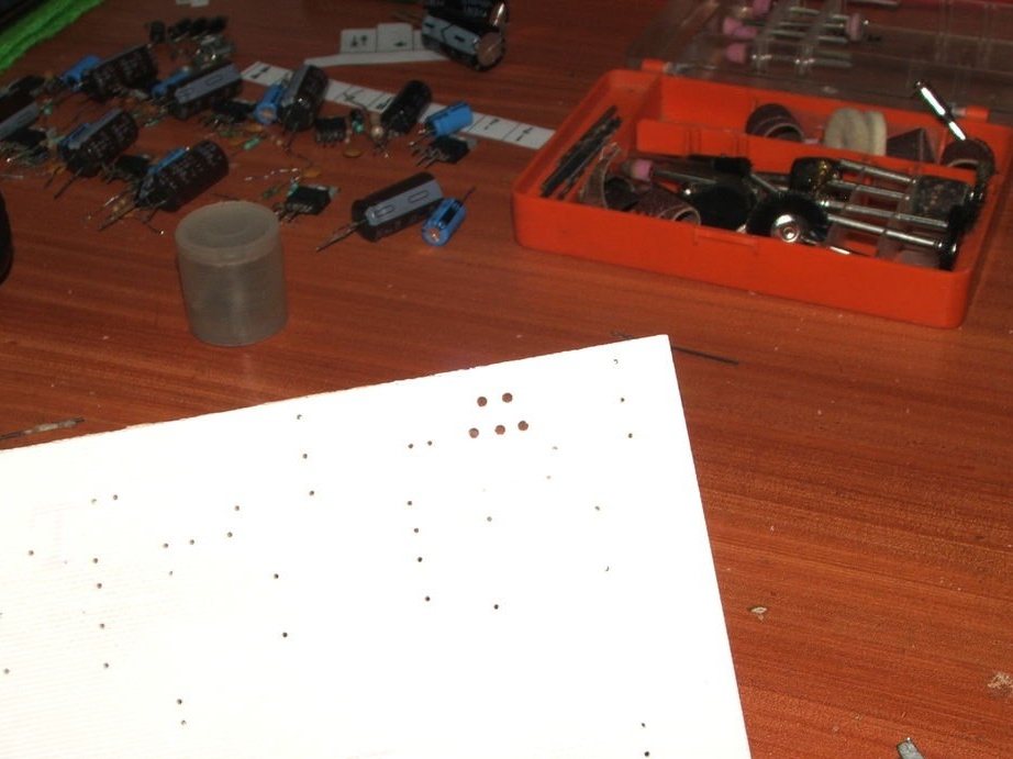
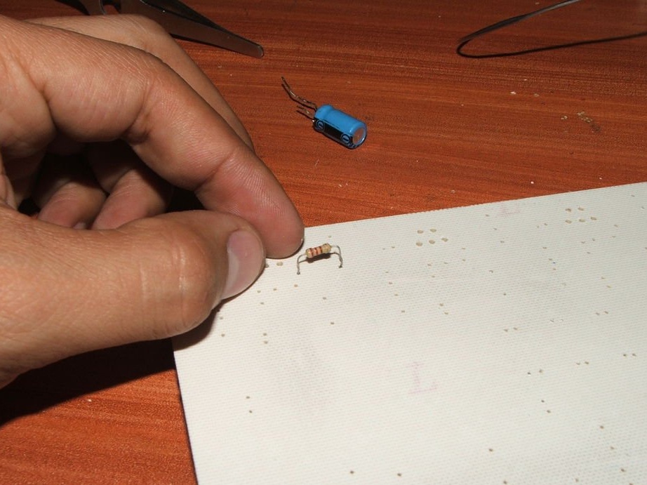
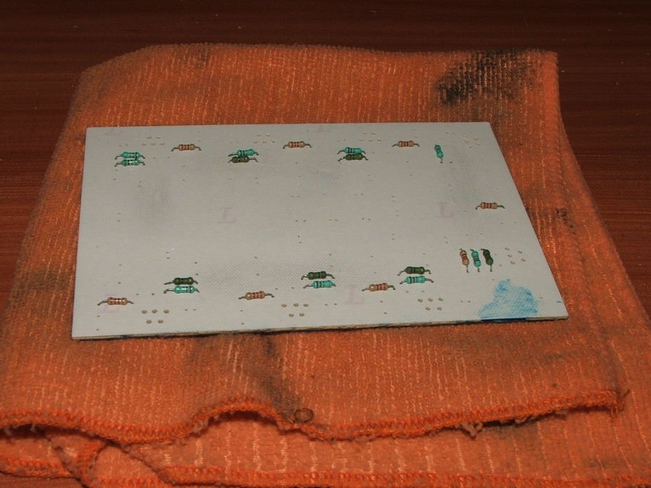
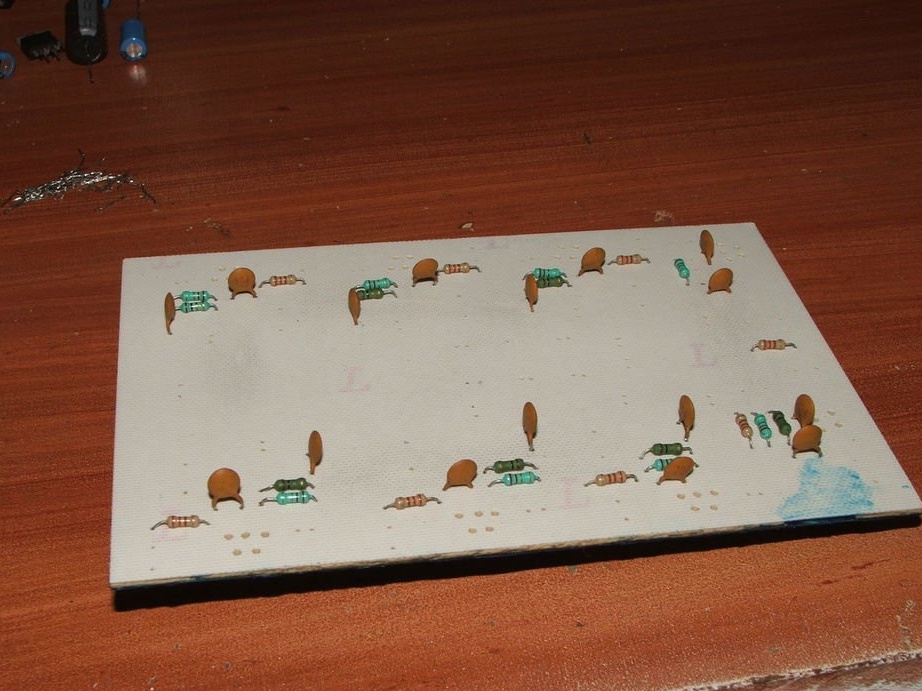
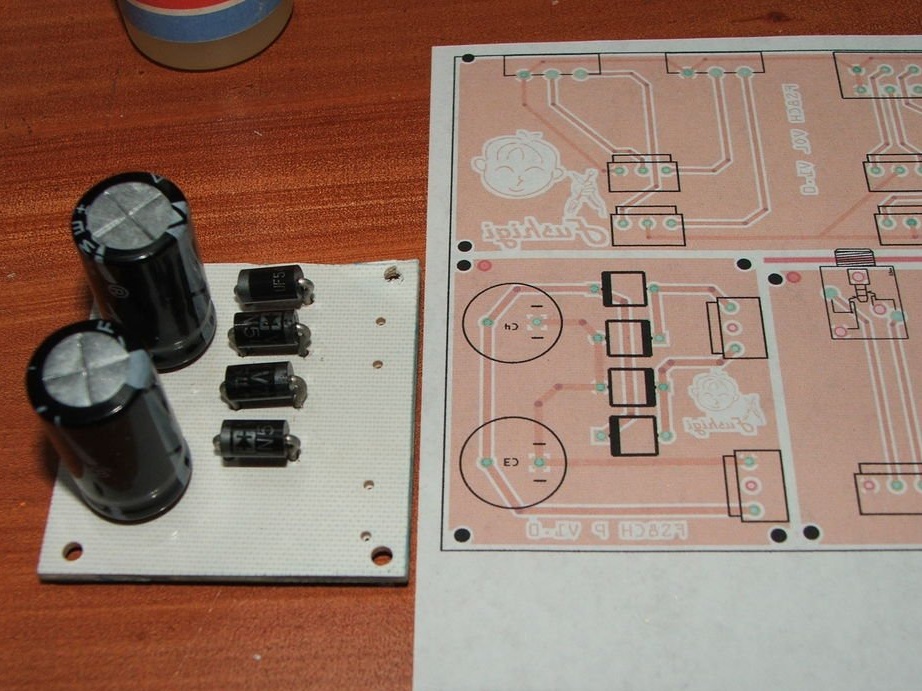
Insert the components, starting with the components of a shorter height, and bend the terminals outward and solder in the following order:
Resistors
Ceramic capacitors
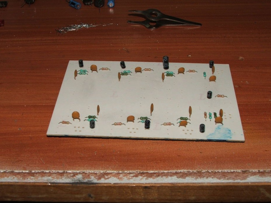
10 uF Electrolytic Capacitors
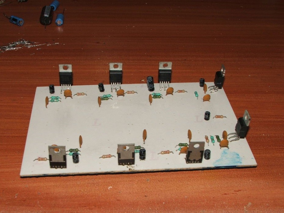
TDA2002 and TDA2003
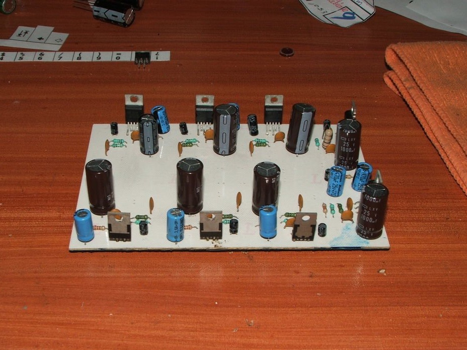
470 uF Electrolytic Capacitors
1000 uF Electrolytic Capacitors
Attachments
Step 8: Heat Sink Radiators
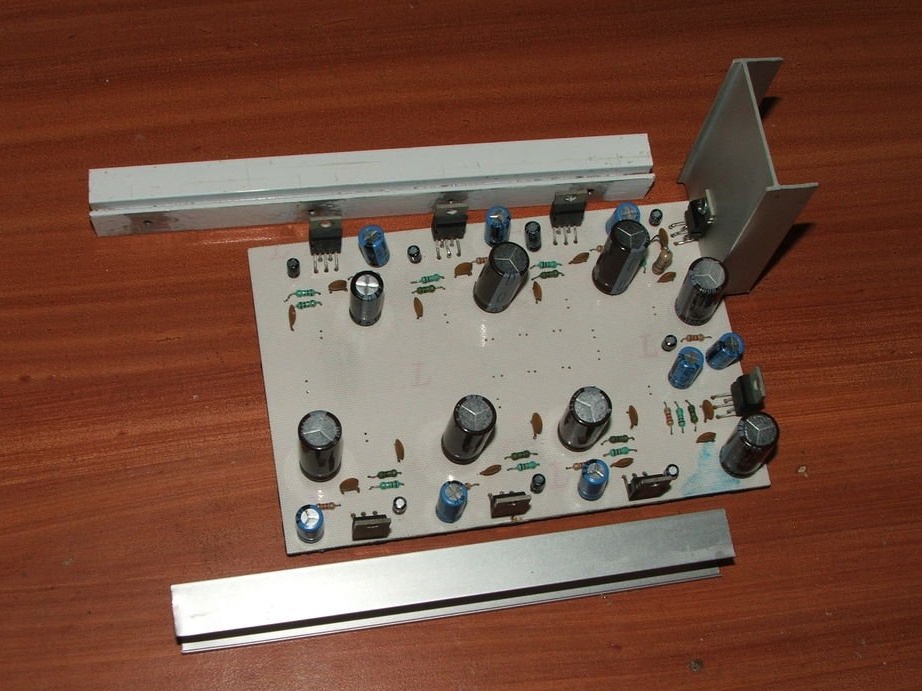
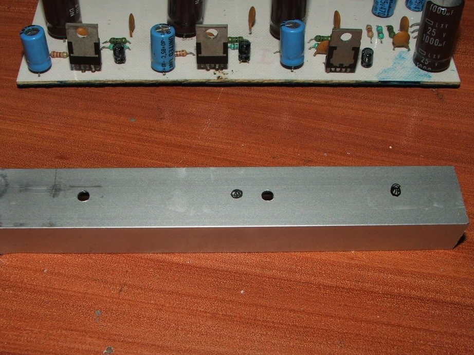
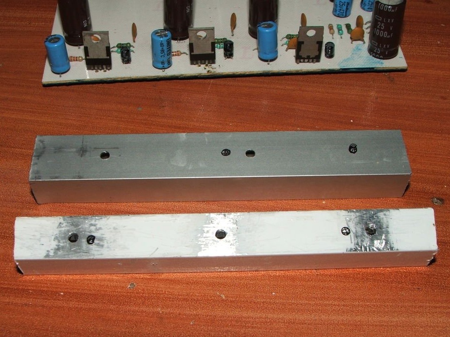
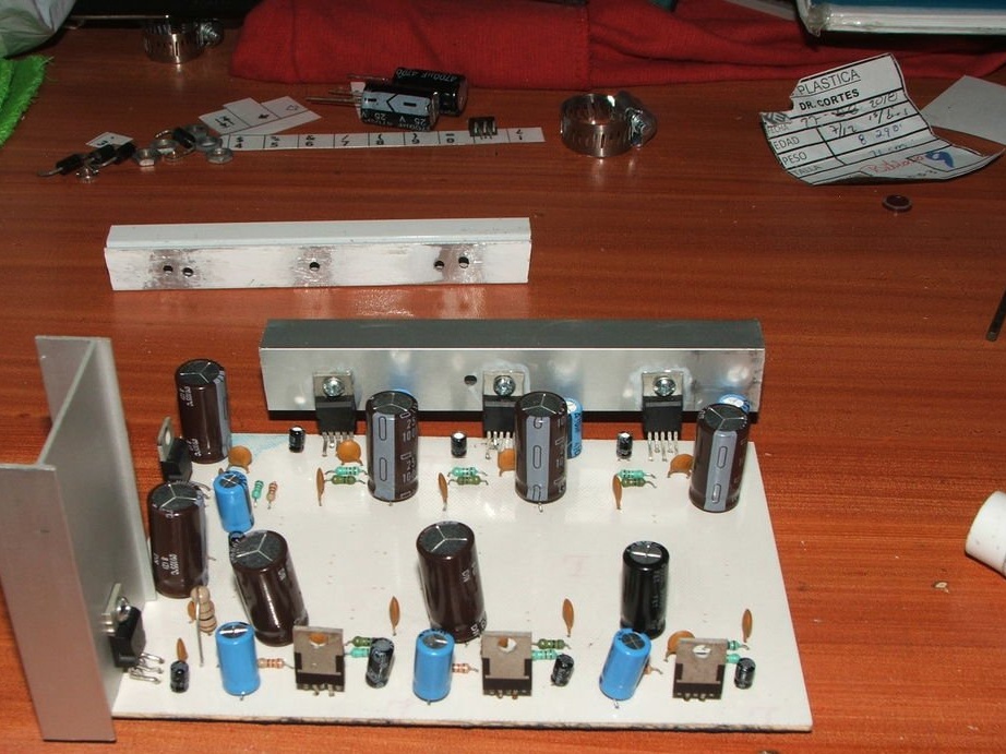
Take a few aluminum profiles and cut them to the right size for TDA2002 and 2003
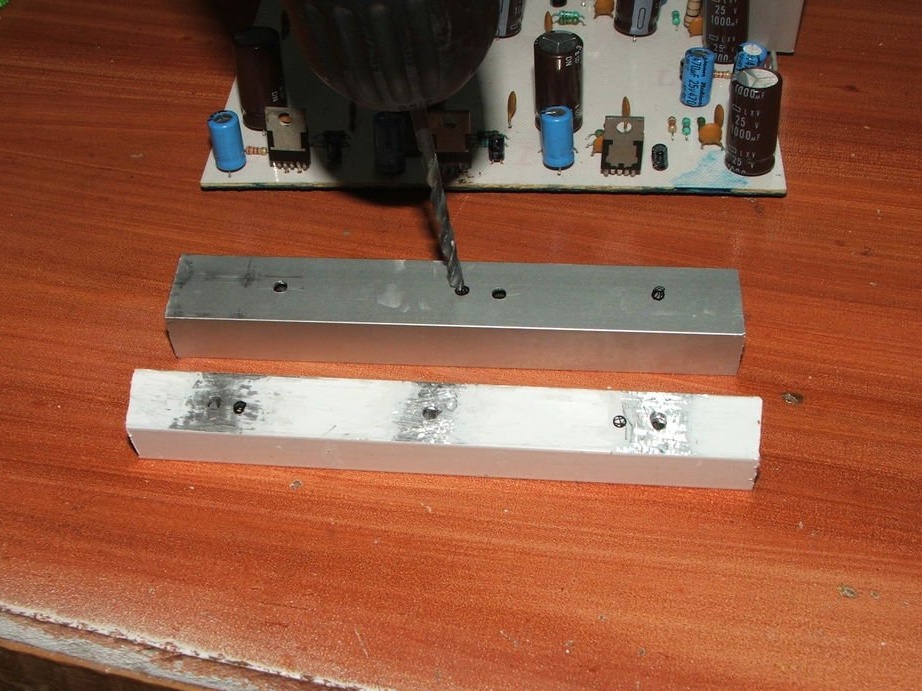
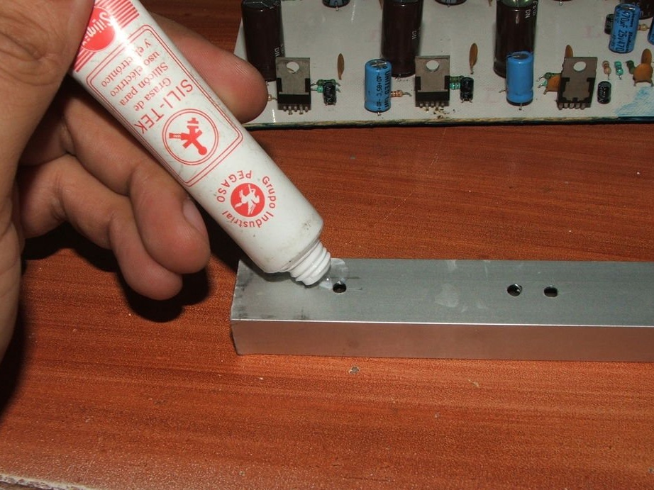
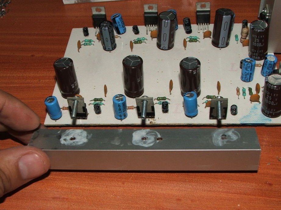
They are drilled in the right places and coated with silicon grease for better heat transfer.
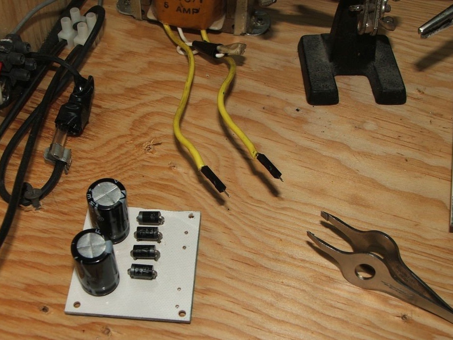
Step 9: Volume Control, Power Supply, and Inputs
Materials prepared and processed, as in the previous printed circuit board:
The circuit is printed.
Duct tape.
Ironing.
Soaking in water.
Paper removal.
Retouching tracks.
Iron chloride etching.
Toner Removal.
Cleansing with alcohol.
Attachments
Step 10: Cut the PCB and apply the mask
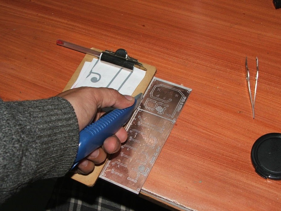
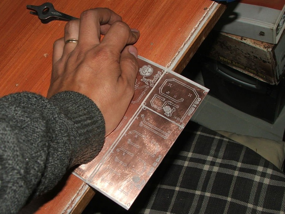
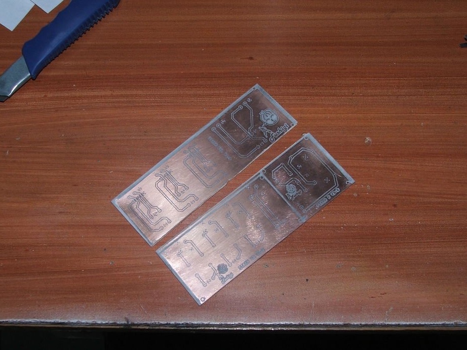
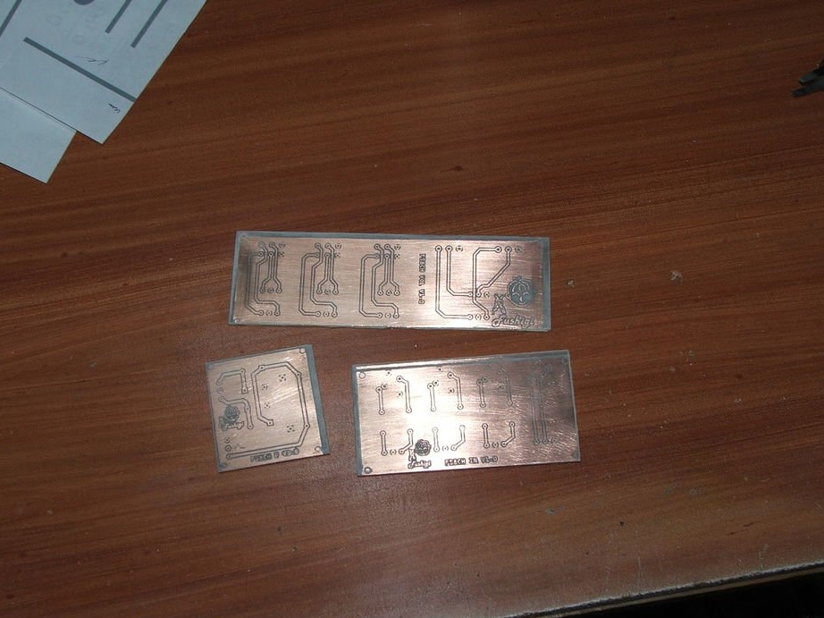
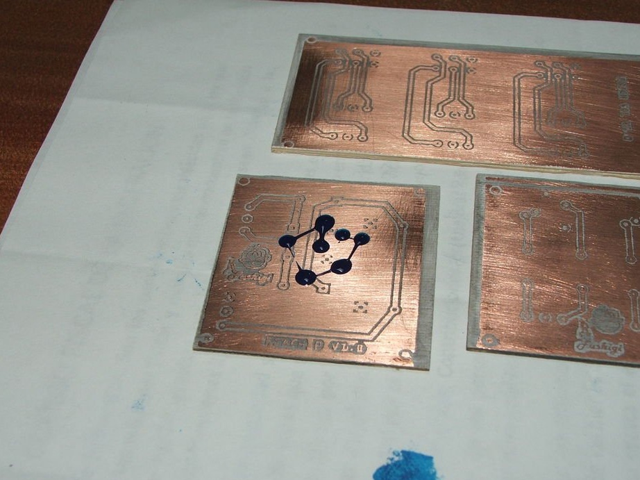
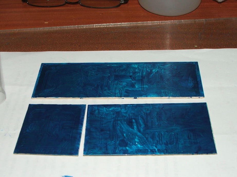

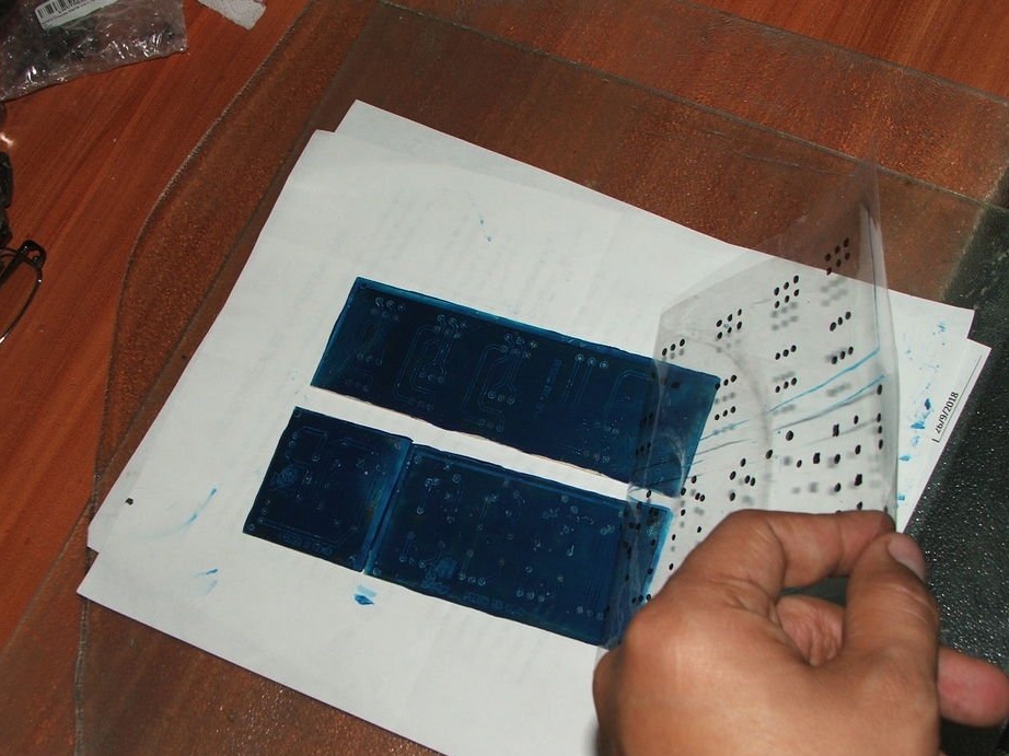
The board is cut with a cutter and a ruler.
Then apply a mask for solder with a wooden stick.
Cover the boards with a plastic sheet and smooth the mask with a card.
Draw tracks with a marker.
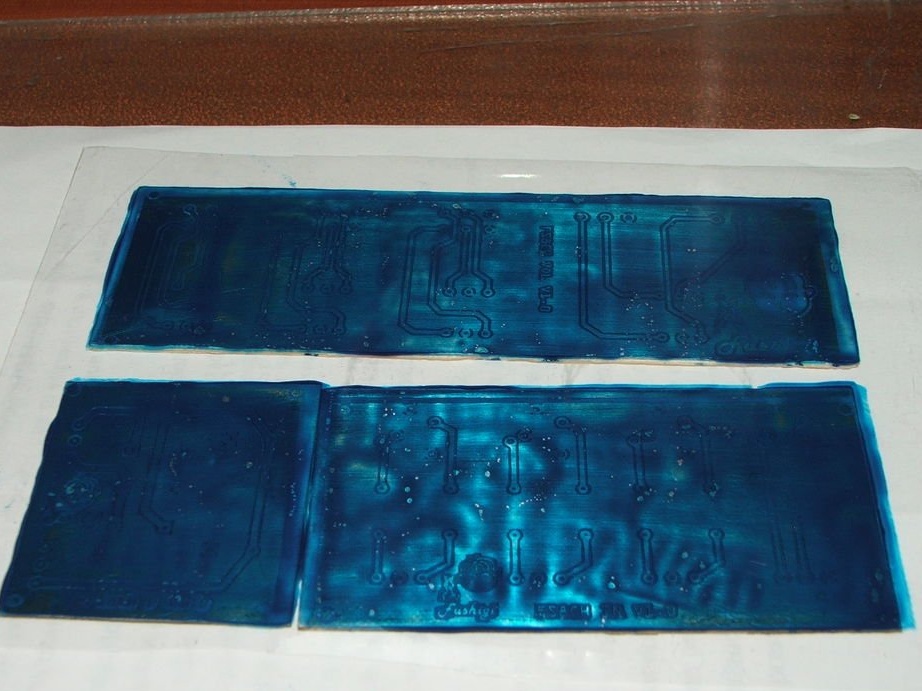
Then the boards should be exposed to ultraviolet radiation or the sun for 5 or 10 minutes.
Then remove the plastic and clean the circuit board with alcohol.
Attachments
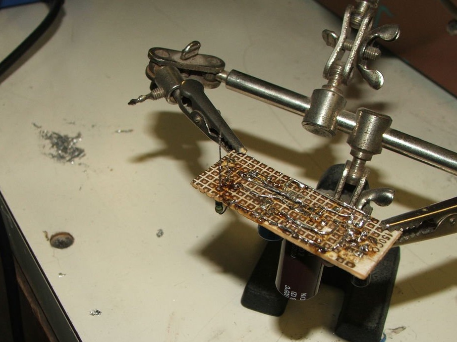
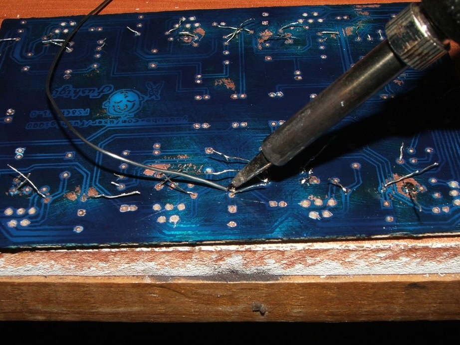
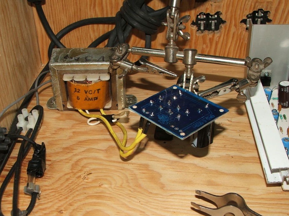
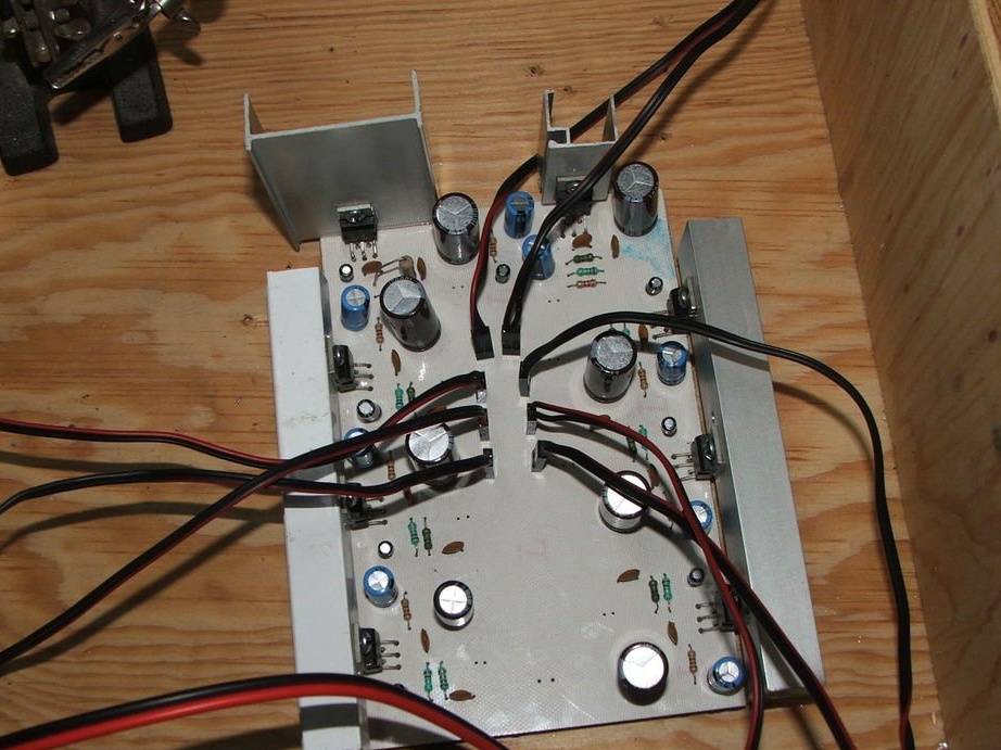
Step 11: Soldering Components
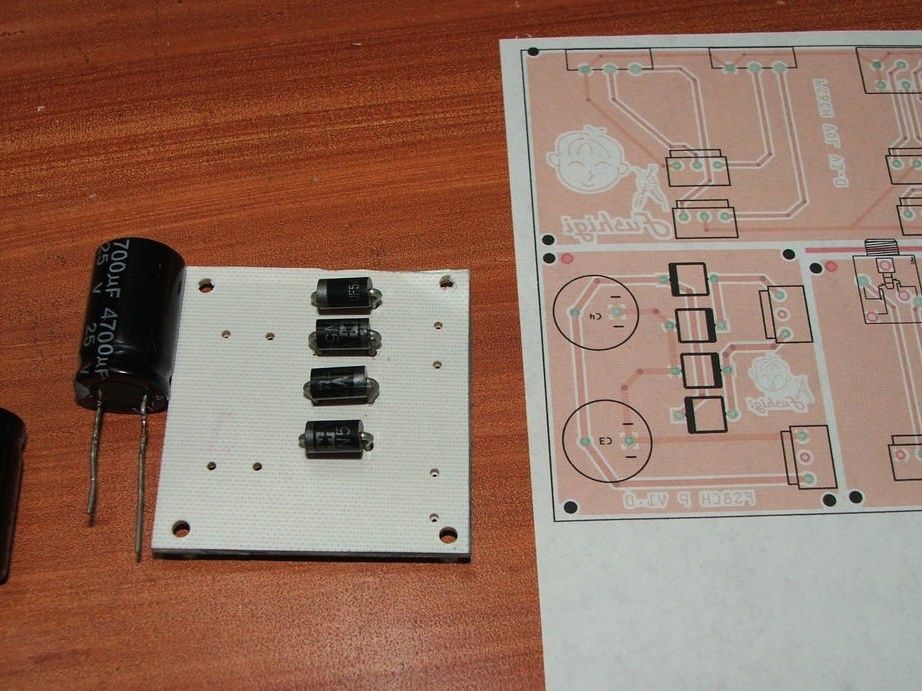
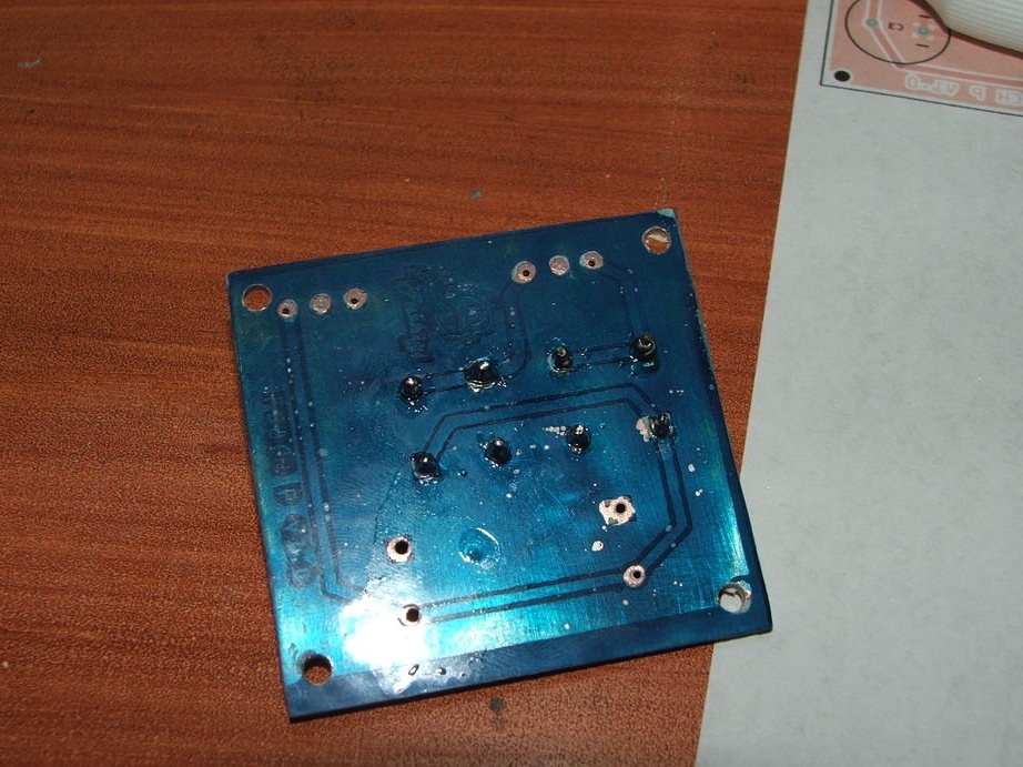
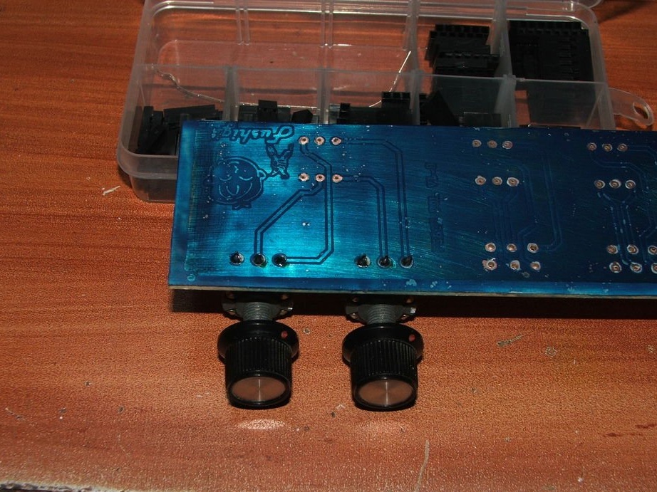
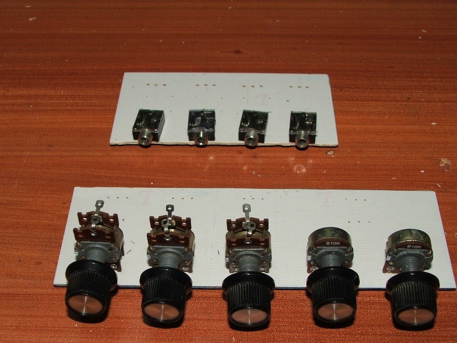
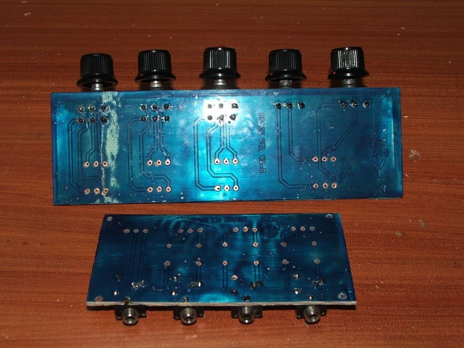
Drill the appropriate holes and solder the components on the 3 printed circuit boards, as shown in the diagram.
Attachments
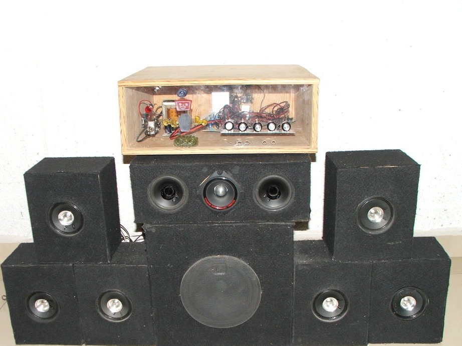
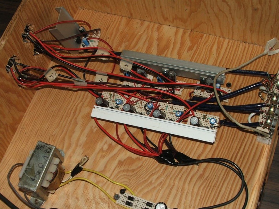
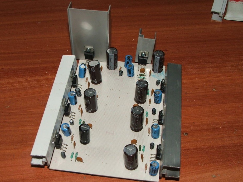
Step 12: final build
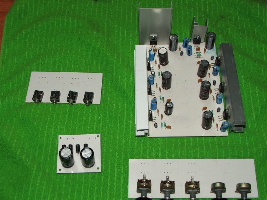
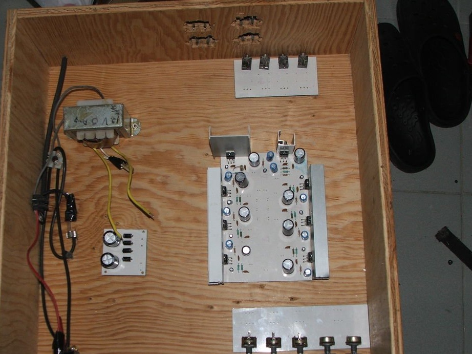
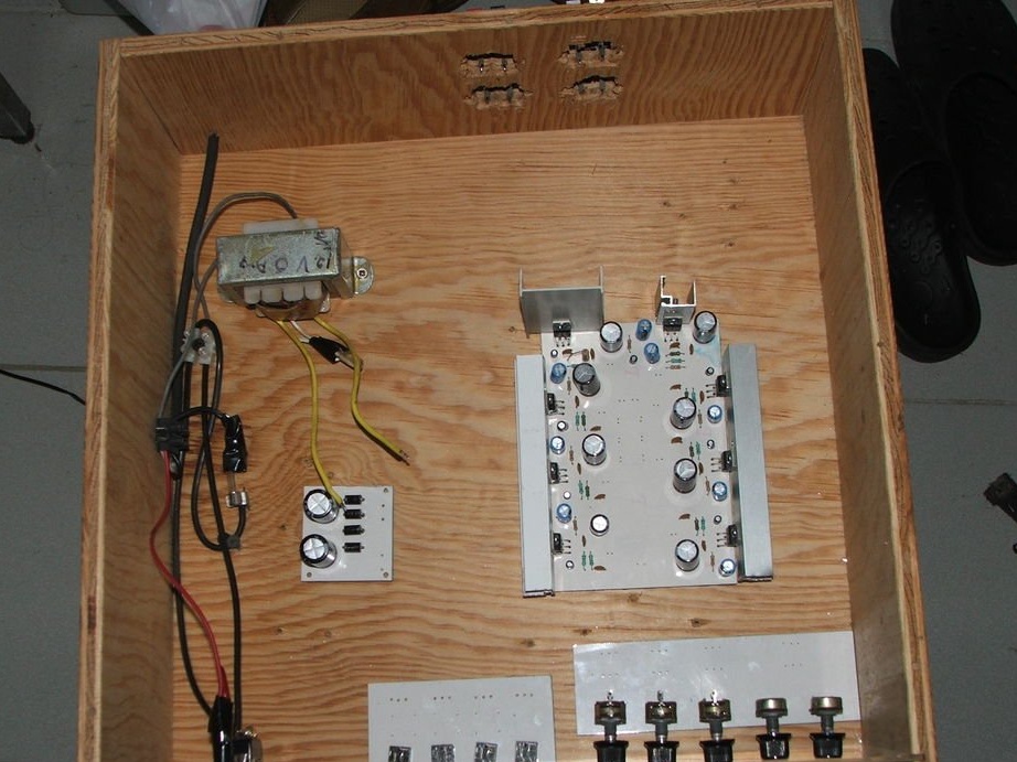

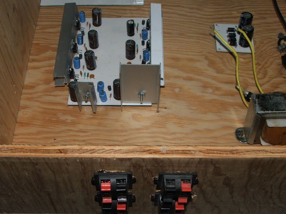
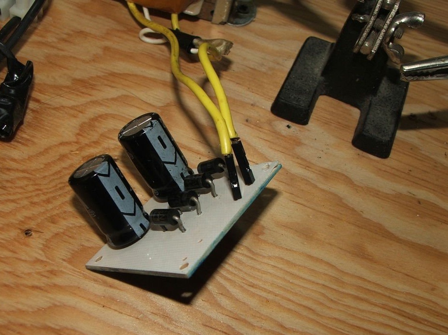
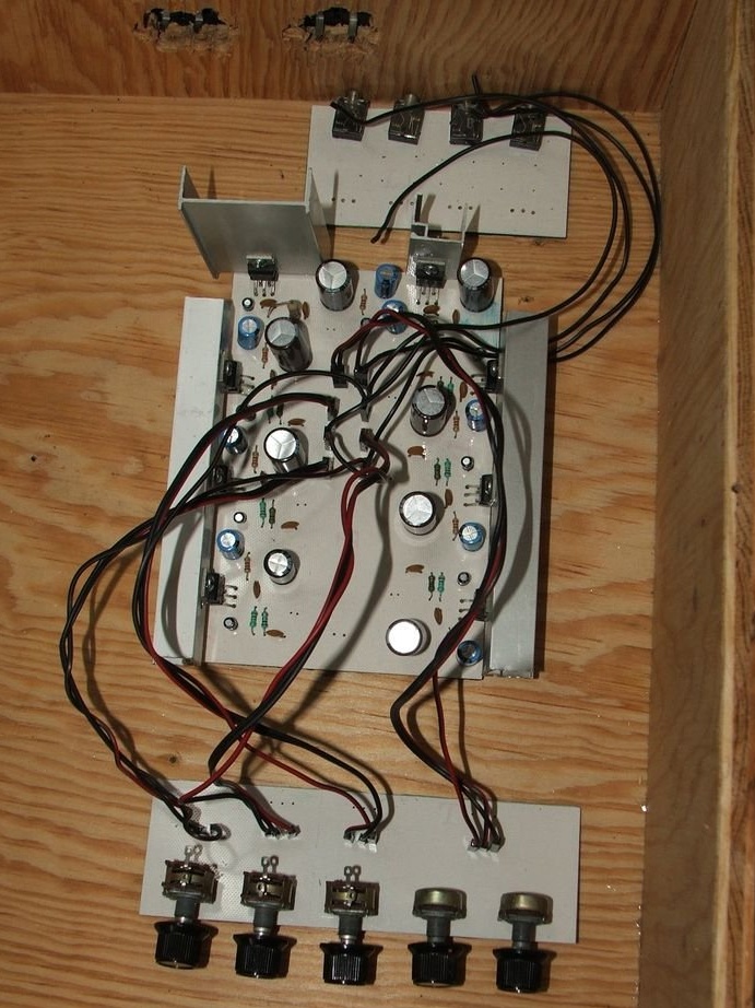
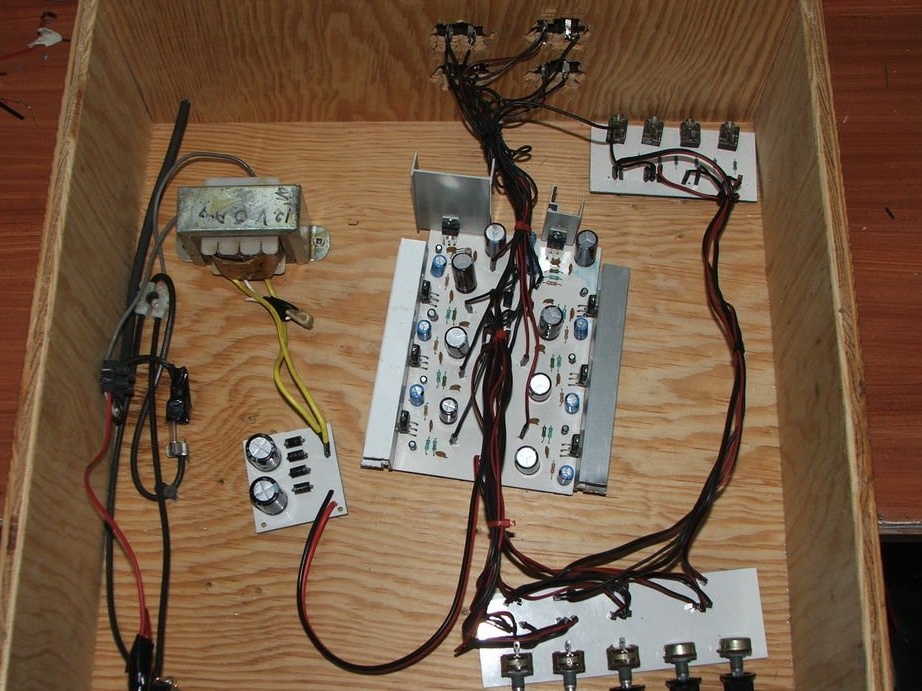
At the last stage of the assembly, we take the printed circuit boards and solder them according to the scheme, starting with the power source, then the volume control and inputs, and then the contacts for connecting the speakers.
Then we put the assembled amplifier into the case. We connect speakers with a rms value of 8 W or PMPO 80 W 4 Ohms for the front, side and rear. Subwoofer 10 W RMS or 100 W PMPO 4 Ohms. The center has 2 speakers of 8 watts each, an RMS value of 4 ohms, and a high-frequency twitter with a remote control of 1000 watts and 8 ohms. thus there is a 4 ohm resistance for maximum power.
This amplifier has 60 watts RMS or 600 PMPO or more.