
If you are engaged in the repair or design of various electronics, then the device that we will consider in this article is simply necessary for you.
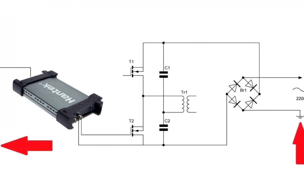
The author of this project is Roman (YouTube channel "Open Frime TV"). The history of the creation of this device began a long time ago, when the author had just begun to study power supplies. For clarity, the author had to buy such a USB oscilloscope, and use it to look at the processes taking place in the circuit.

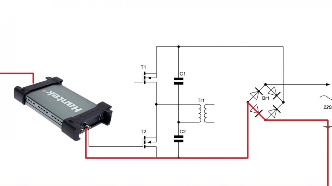
But there is one important point that was missed, namely, galvanic isolation from the network. And in the end, the author safely burned his oscilloscope plus all the rear USB ports of the computer and everything that was connected to them. In general, the damage was very impressive.
After this incident, Roman began to sort out what caused such a troubles. As it turned out, the whole thing turned out to be in common ground. They turned out to be common between the computer and the device, and when the author poked into the high-voltage part of the circuit, a breakdown occurred through this sinister earth.
As a result, I had to buy a new oscilloscope, which hit the budget a lot. Now the author decided to show how to make such a simple device that will help all hams to avoid the same setback.
And so, what does galvanic isolation mean? This is an ordinary network transformer with a one-to-one transformation ratio (1: 1).
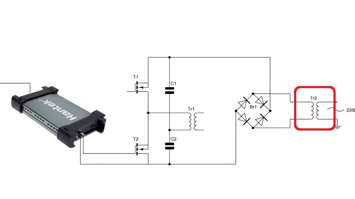
Thus, we get the same 220V output, but not connected to the network in any way.
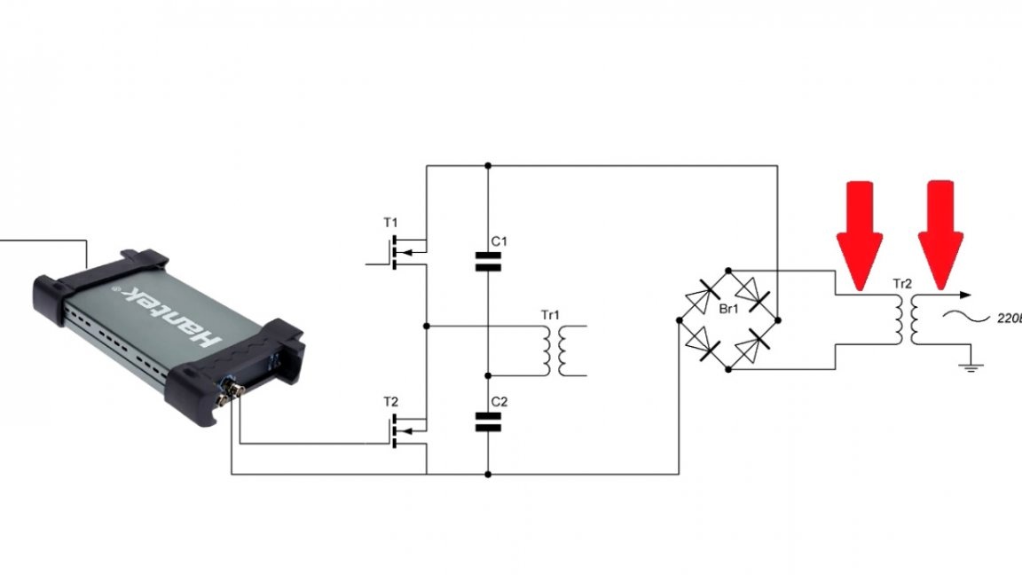
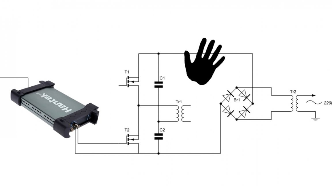
And one more big plus of such a thing: if you accidentally touch the bare wires, then you will not be killed.
We figured it out, but where to get the right transformer? For these purposes, transformers from old TVs are excellent, they have a fairly large size, and sometimes even windings with the ratio we need 1: 1. For example, at a local flea market, the author found such a TSA-270-1 transformer.
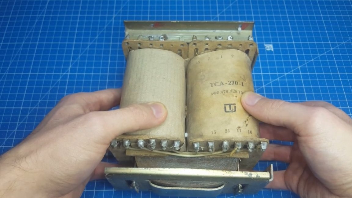
Consider this transformer for a song, but its output winding was not powerful enough. Its current was only 0.32A, and this, as you know, is not enough for our purposes.
Then it was decided to rewind the transformer. Especially for this purpose, the author even bought this wire:
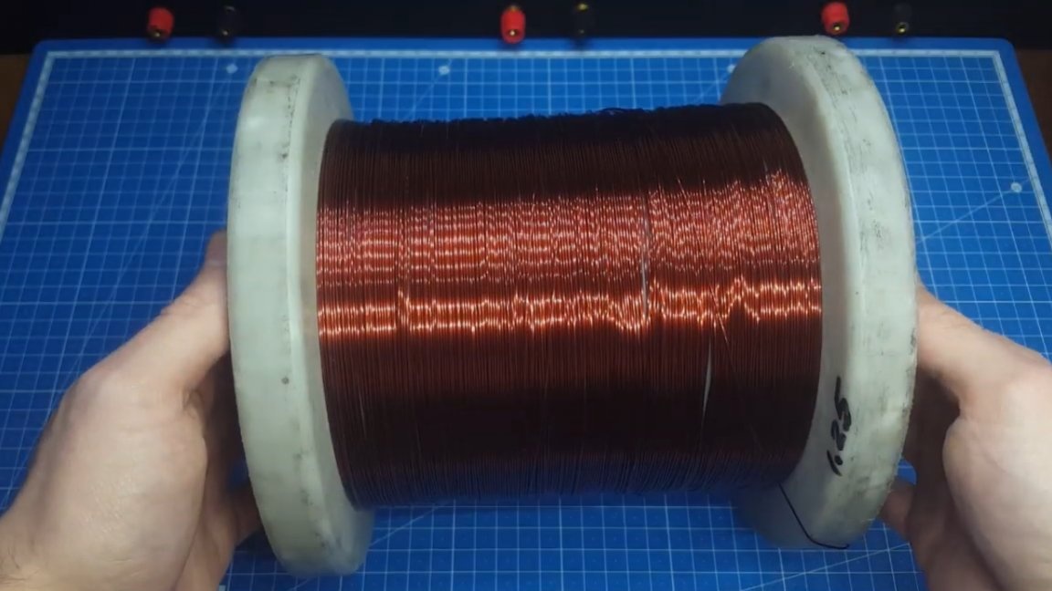
It would seem that everything is ready for winding, but in connection with some circumstances this process dragged on, and strangely enough it saved the author from useless work. Now you will find out why. Some time after the start of the project, the author was looking for some things in the barn and came across a box with a transformer.
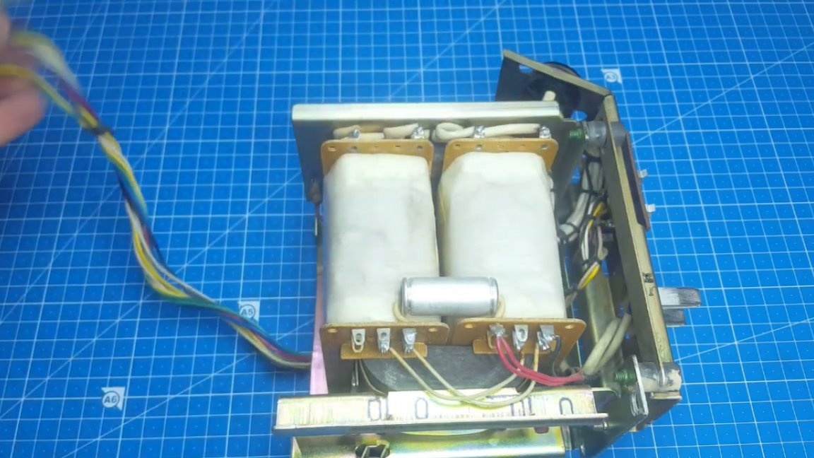
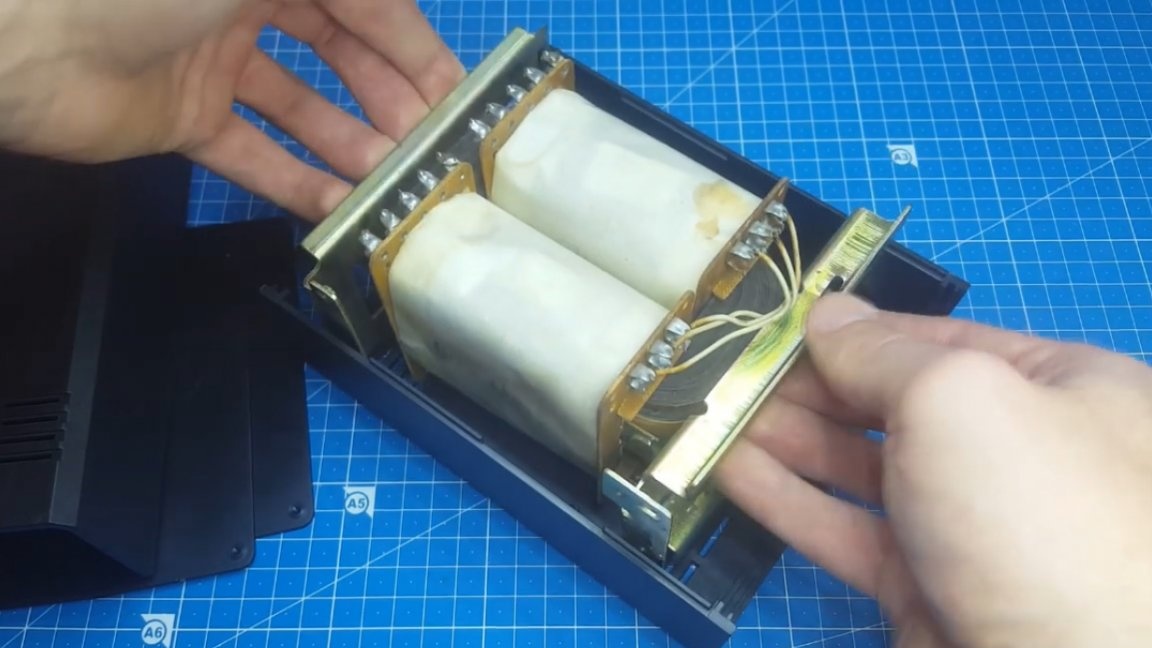
It looked like a TSA, but a little smaller in size, which is a plus, since it will be more convenient to do on it. But that wasn’t all. By googling the author realized that his high-voltage winding is more powerful than that of the TCA and can give a current of 1A. So it's generally gorgeous, it’s not even necessary to rewind anything. It is on this transformer, the brand of which is TS-250-2P, that our galvanic isolation will be built.
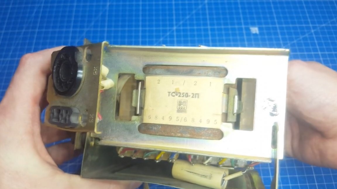
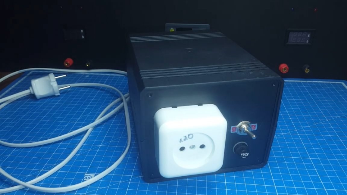
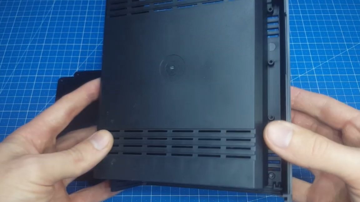
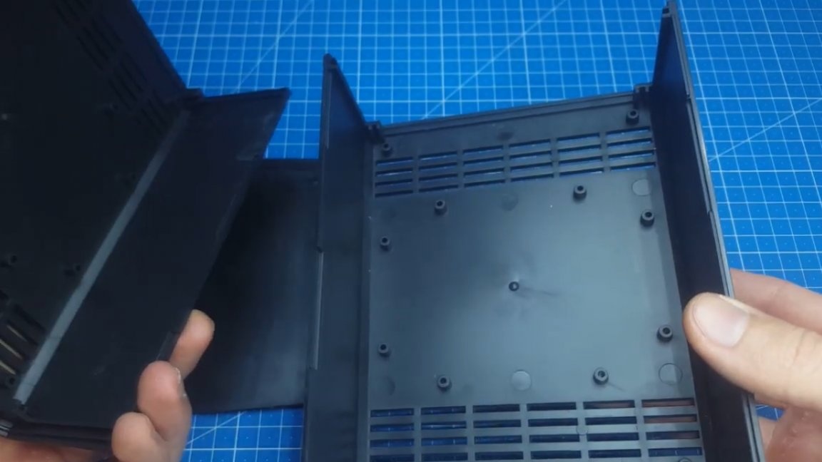
First of all, we need to disconnect all the wires and remove unnecessary parts that increase the size of the transformer itself. After which, after making the necessary measurements, such a plastic box was ordered here, in which our transformer fit perfectly.
But in addition to the transformer itself, it was decided to install another useful function here, namely, the inclusion of a load through a light bulb. This is very convenient, for example, if the device is turned on for the first time, because in the event of a short circuit, the light will limit the current and nothing will burn.
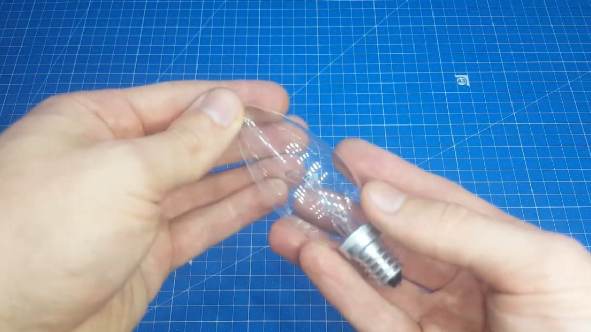
Since the place in the housing is very limited, we will use just such a miniature lamp, which is designed for voltage 220V, power 60W.
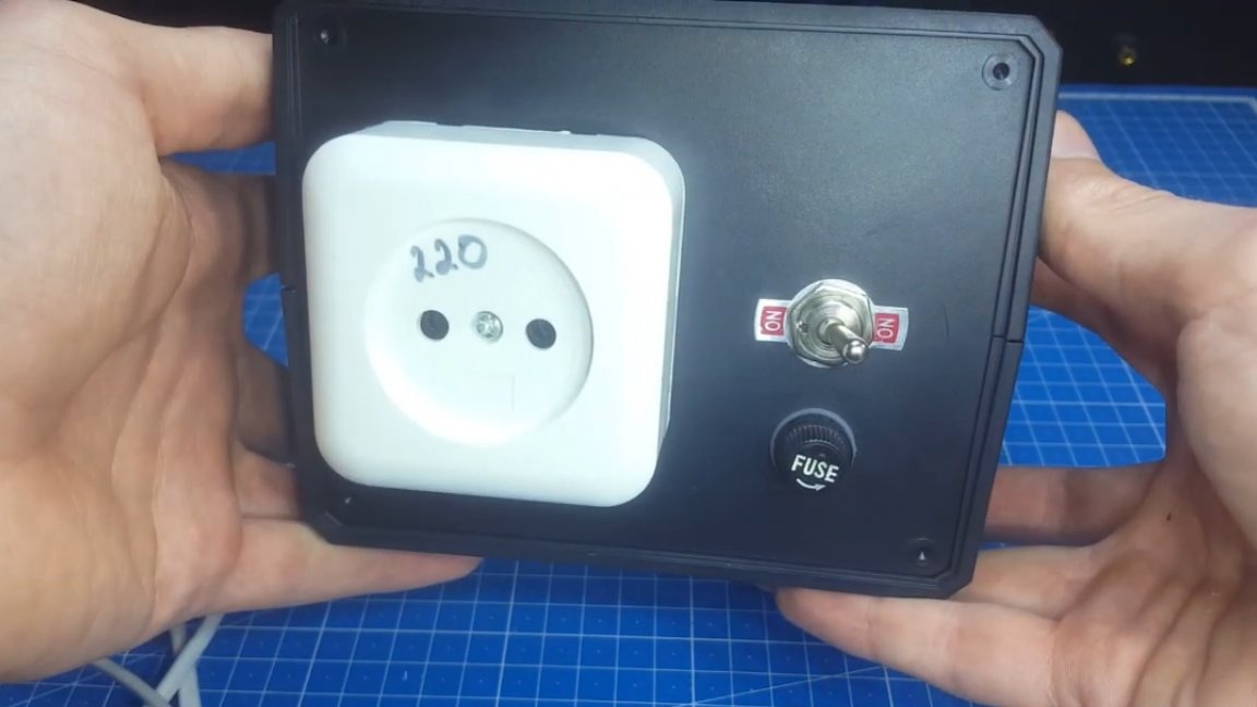
Now let's get down to preparing the hull. It is necessary to fix the socket on it, as well as a switch that will allow you to connect or disconnect the incandescent lamp.
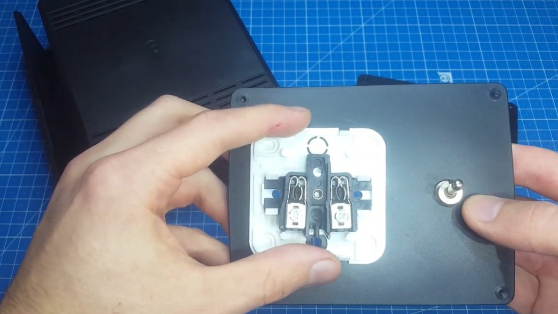
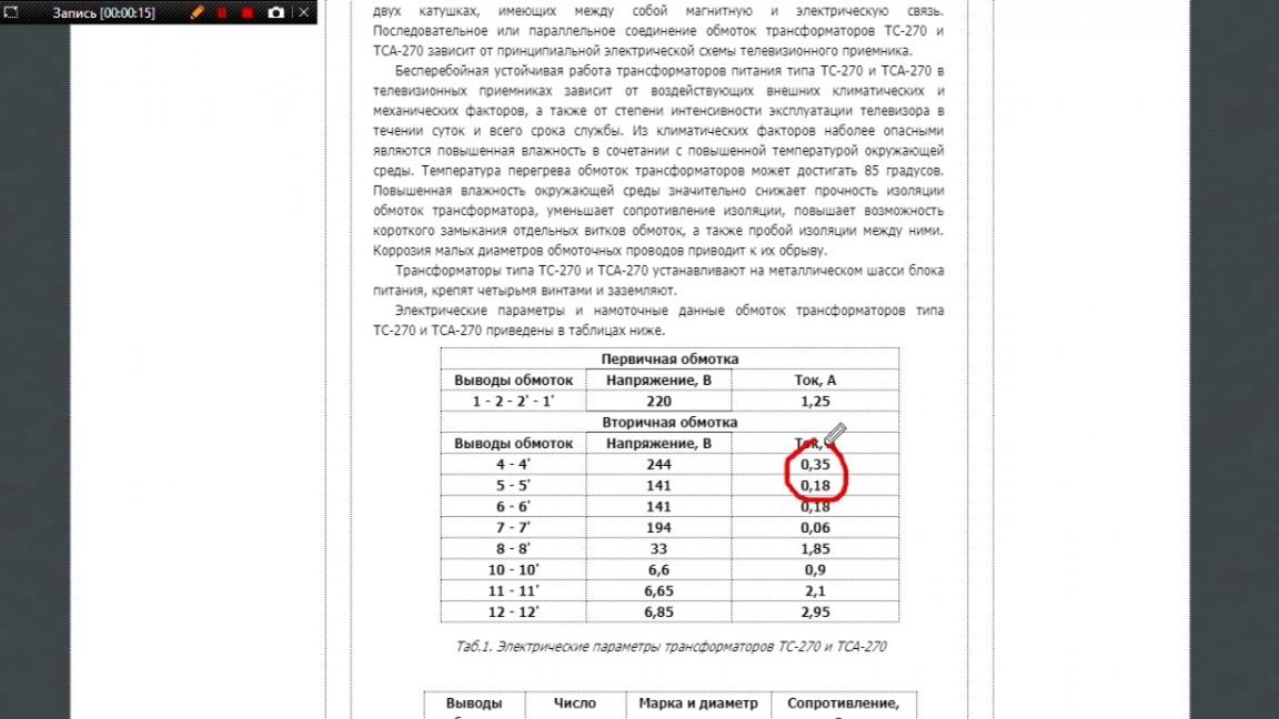
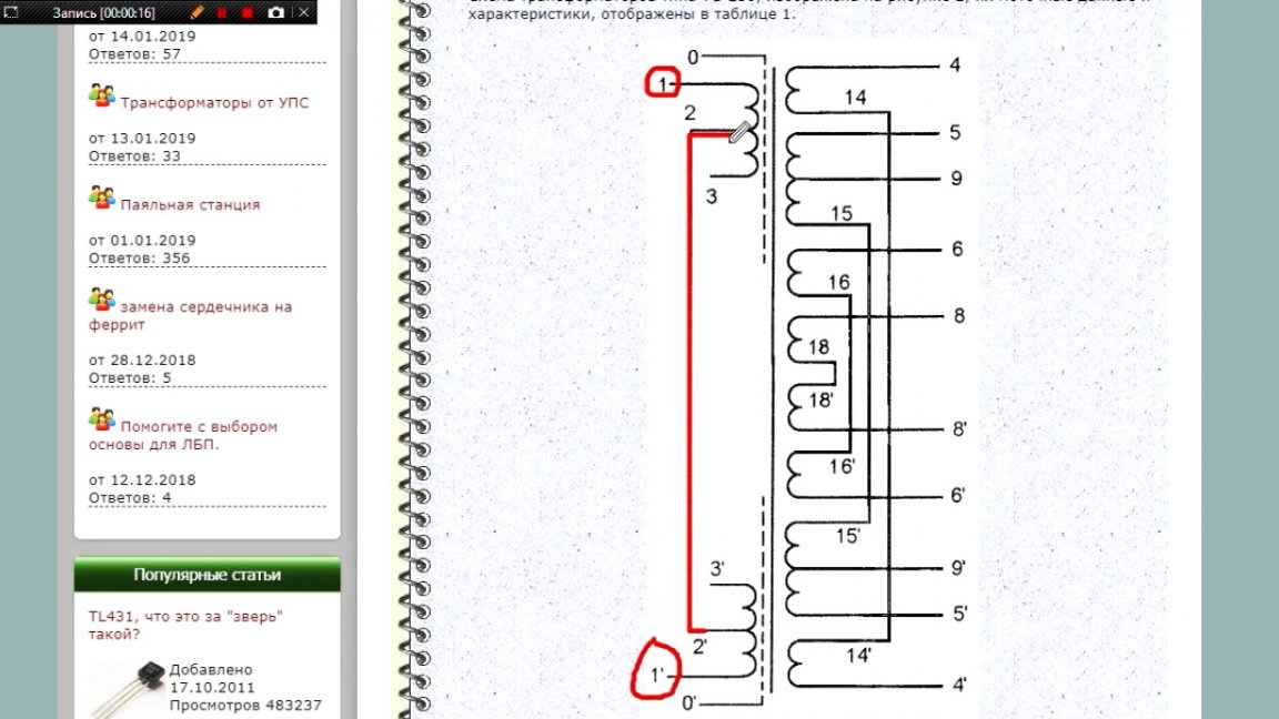
This is done elementarily, we will not even dwell on this. It is also necessary to add another hole for the fuse, but we will do it a bit later. Now let's get down to the preparation of the transformer. We find documentation on the Internet, it can be seen from it that the mains voltage must be applied to pins 1 and 1 '.
And contacts 2 and 2 ’must be closed between themselves.
As you can see, there is nothing complicated. We pass to the secondary winding. There are several of them, but as you can see, there are no pure windings for 220V. Sorry of course, but nothing, we will get out. Below we can see how the author checks the voltage on his transformer.

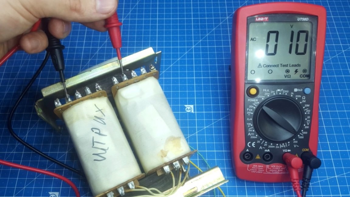

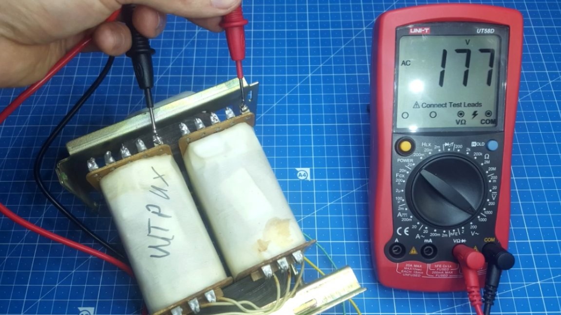
They basically correspond to the documentation. We proceed further in this way: we need to connect all the windings in series. On the transformer frame, in order not to get confused, the author wrote the word “stroke”.
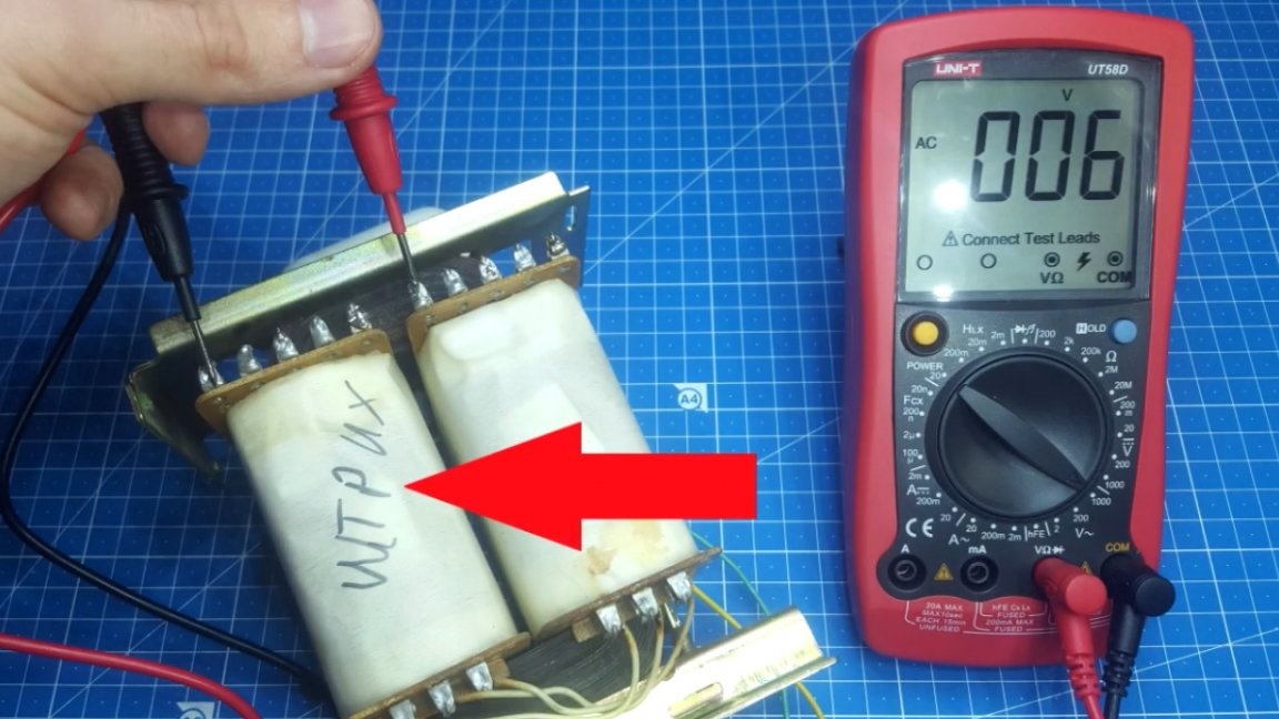
Now we take, for example, winding 4 and 4 ’and connect it to the main winding 5 and 5’. Now the voltage will be removed from pins 5 and 4 ’.
Next to them we add another winding 6 and 6 ’, just as sequentially. And now, eating is already happening with pins 5 and 6 ’.
We connect it all in the iron and see how many volts we got.
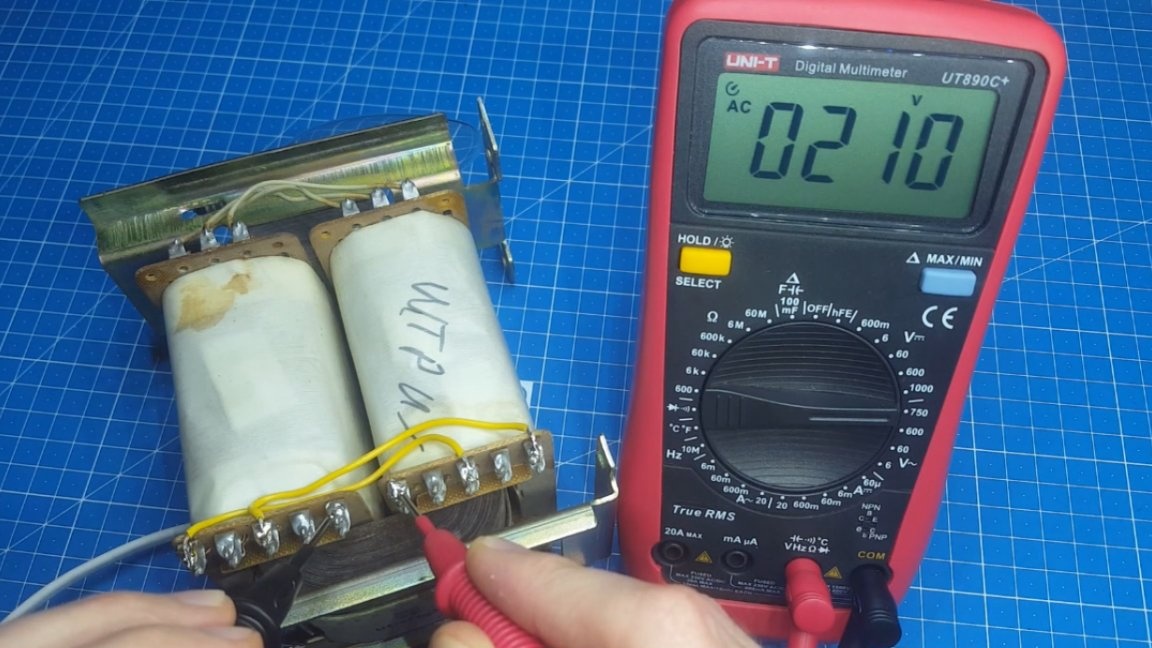
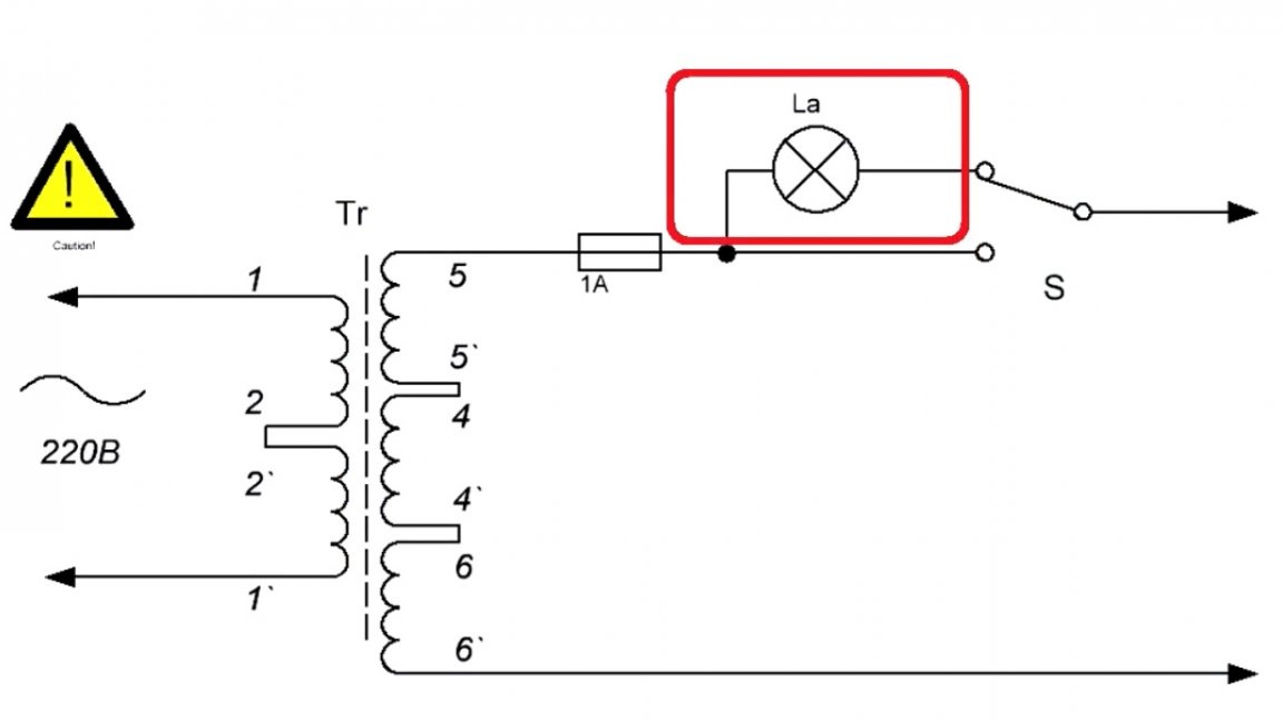
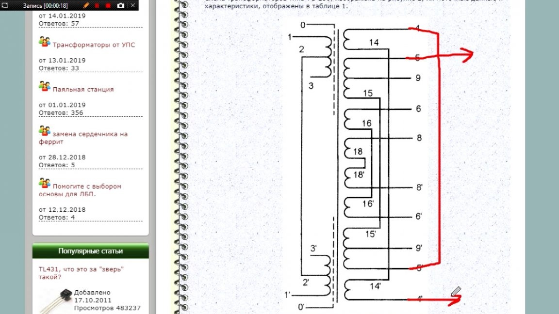
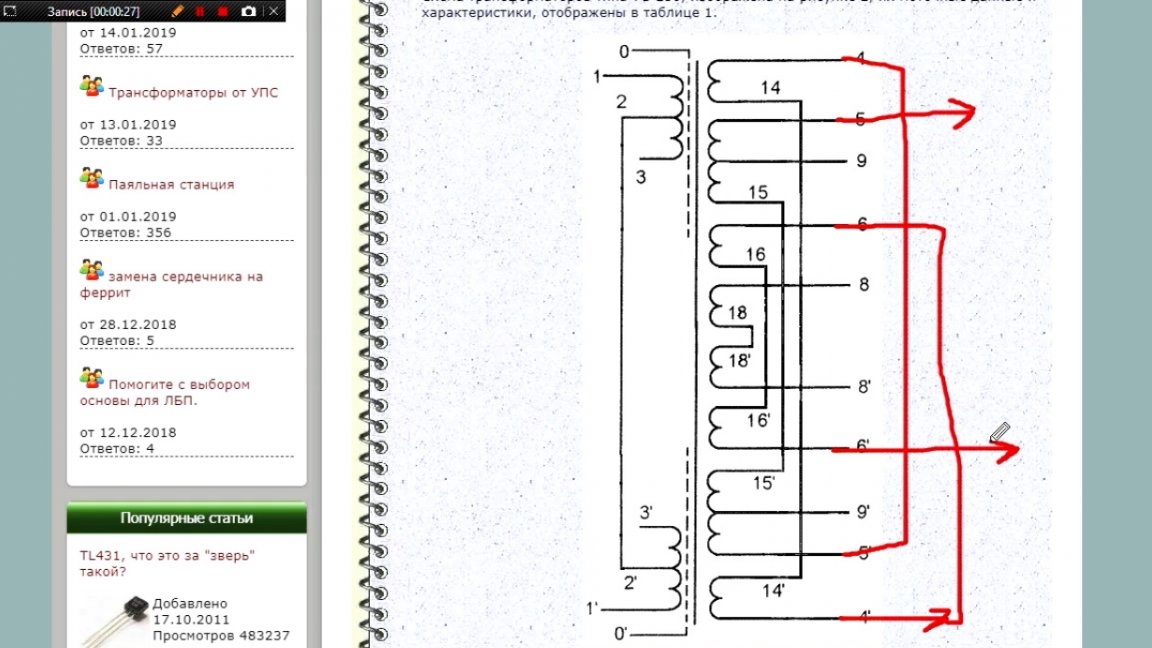
As you can see, the multimeter shows a voltage of about 210V, and this is more than enough. And especially for those who did not understand the connection scheme, the author prepared a visual drawing, based on which even a child can assemble this scheme.
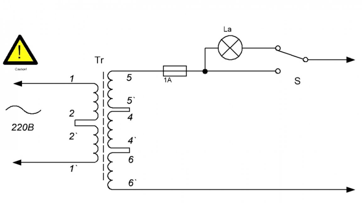
As you can see, the figure shows a fuse with a lamp, and a switch, in general, full stuffing. And now it's time to install everything in the case.
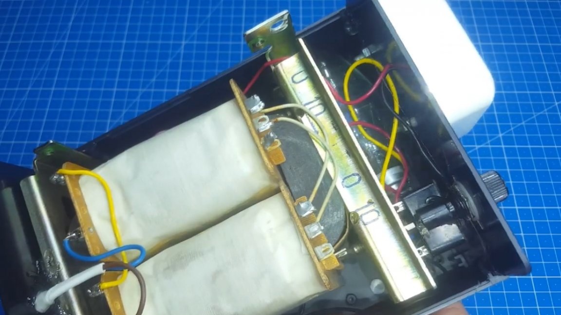
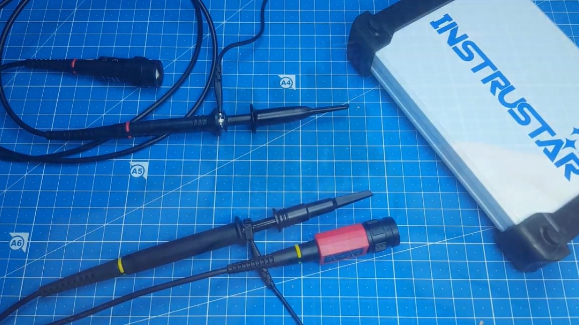
Details fit tightly, but most importantly, everything fit. On this assembly is completed, but that's not all. With USB oscilloscopes, a standard probe with a 1:10 divider can only watch low voltage.
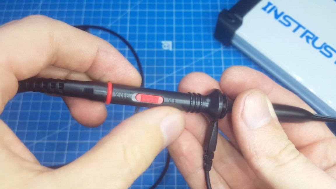
And in order to safely climb into the hot part of the circuit, you need to buy just such a probe with a divider of 100. Yes, it is not cheap, but it saves a more expensive oscilloscope from burning out. The measuring range with such a probe is greatly expanded.

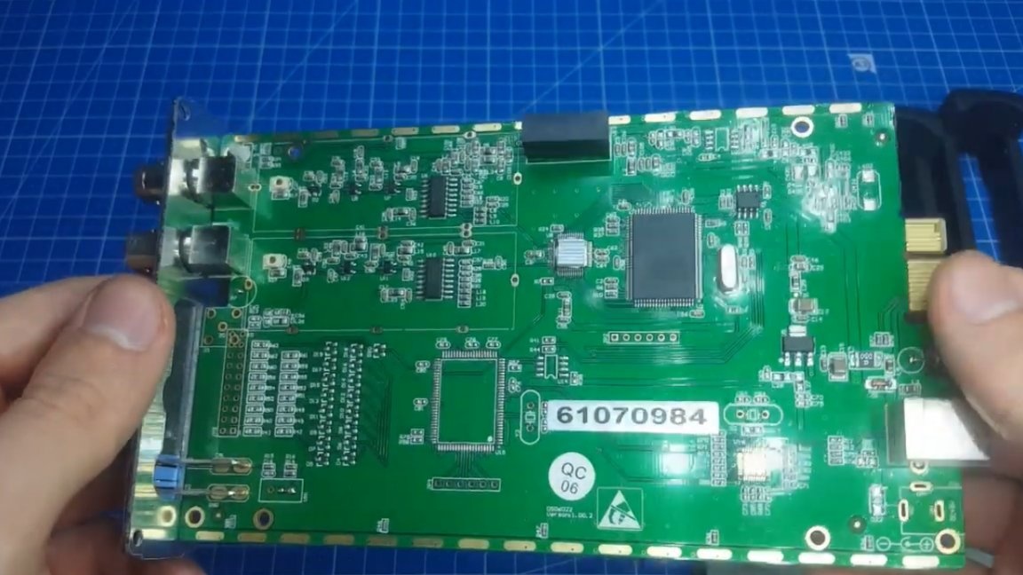
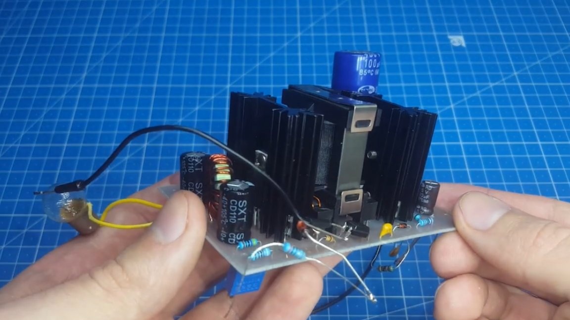
Well, in conclusion, you can conduct tests of the device we just assembled. For this we need any homemade product. The author will use the power supply that is currently being developed.
We plug it into the network and calmly stand on the transistor's gate, without fear of any pitfalls.
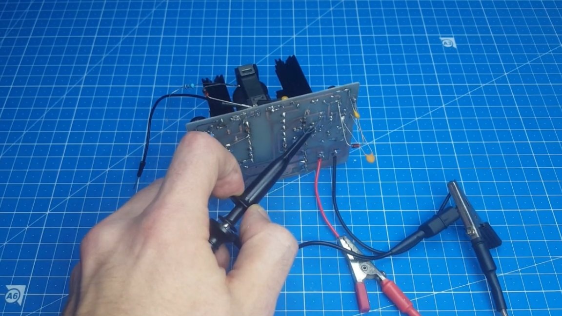
On the screen we can see our impulses.
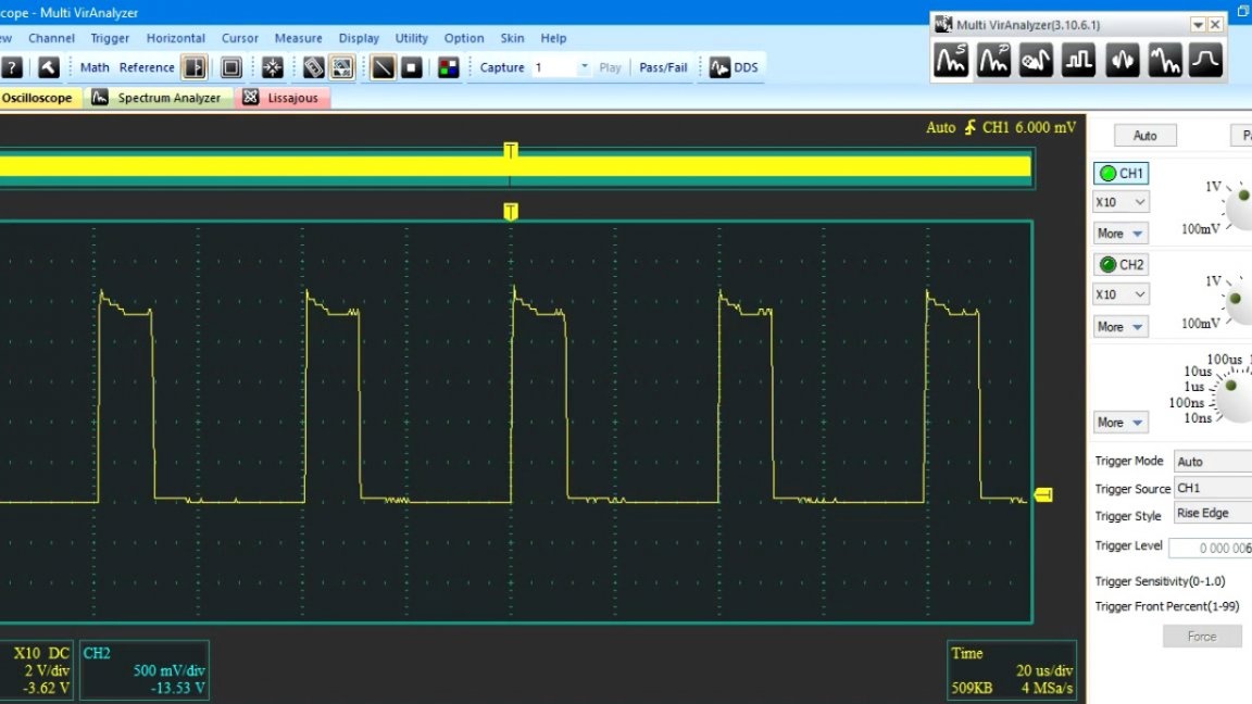
As you can see, everything is clear. In general, the device is really worth repeating, especially if you intend to do electronics in the future.
It is not necessary to take the same transformer as the author, there are many similar models, but people who do not know their values give almost nothing.

In extreme cases, you can take 2 transformers with the same output windings and connect them on the low side like this:
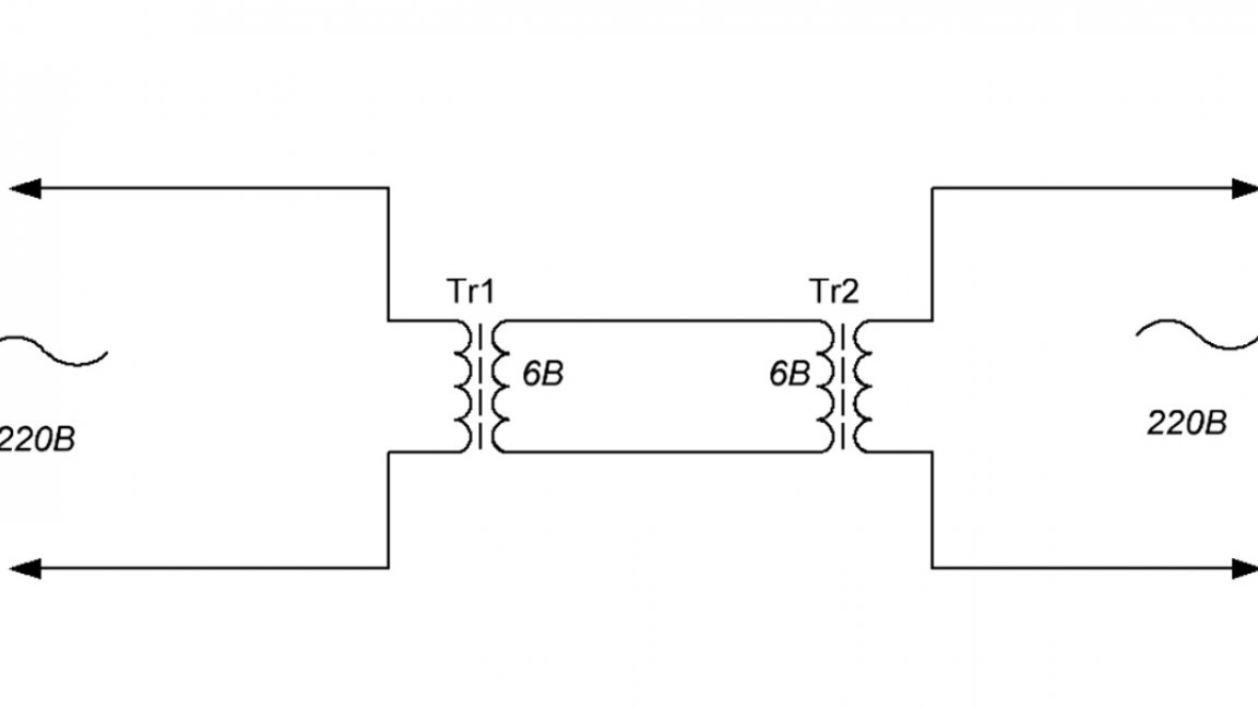
The result will be the same. This is the time to end. Thank you for attention. See you soon!
Video: