
This article describes step-by-step instructions for creating a NiCd (ni-cad) battery charger.
** Warning **
Using the described method, only nickel-cadmium batteries can be charged. The type of battery is usually written on battery packs. New drills and screwdrivers use other types of batteries (Li-Ion, NiMh) that will explode if you use the charger method described below. If you are not sure, then it is better not to use this instruction. Improper design or component design can also lead to fire or battery explosion.
Necessary materials and tools:
Materials:
- wooden block;
- board, thickness 20 - 25 mm. or plywood 10 mm .;
- 32 or 41 mm screws;
- copper wire with a diameter of 6 mm .;
- diode;
- Light-emitting diode;
- several resistors;
- output transformer;
Instruments:
- a screwdriver or screwdriver;
- table saw;
- jigsaw;
- voltmeter;
- drill 3 and 4 mm .;
- soldering iron, solder, flux;
Step One: Making Bars
Cut two wooden blocks, the thickness and the size of the protruding part of the battery pack. The bars will hold the battery pack in place.
Blocks should be the same thickness. On one bar, make a v-groove so that the rounded portion of the battery pack fits into it. On the second bar, using a table saw, make two grooves. These grooves may vary in shape. It all depends on the shape of the battery pack. Using a small piece of wood, fasten the two bars using self-tapping screws. After that, check the fit of the wooden parts.
Step Two: Making the second part of the battery holder
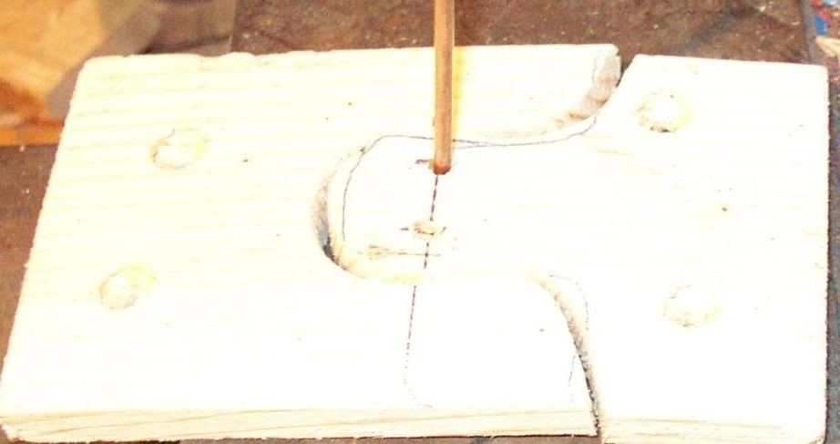
From a thin board, cut the part for the second side. The thinner the better. You can use plywood. For the convenience of further work, using a jigsaw, cut out a curly pattern. Using this cutout, it will be clear where exactly the power terminals on the battery pack will be located.
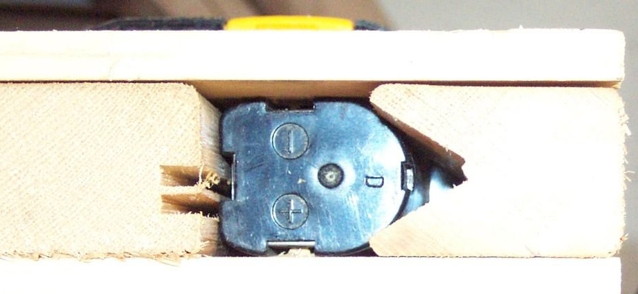
Step Three: Installing Copper Contacts in the Battery Holder
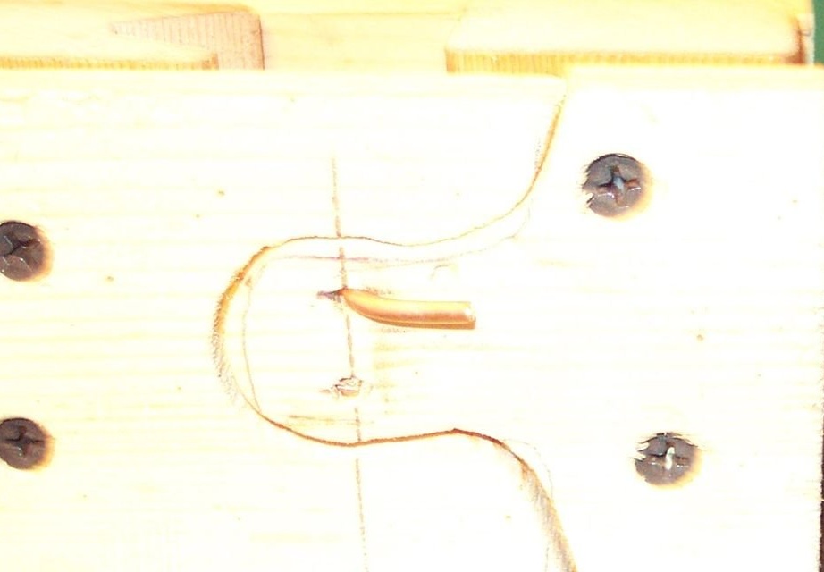
For copper contacts, the master used a single-core copper cable with a diameter of 6 mm. Two holes were drilled for contact between the wire and the terminals of the battery pack. One hole for the positive terminal and one for the negative terminal of the battery.
Then you need to remove the insulation from the wires.Then bend the stripped part into a U-shape so that the wire sticks out. Insert the wire into the holes. The wires should touch the terminals on the battery. To check operability, it is necessary to use a voltmeter.
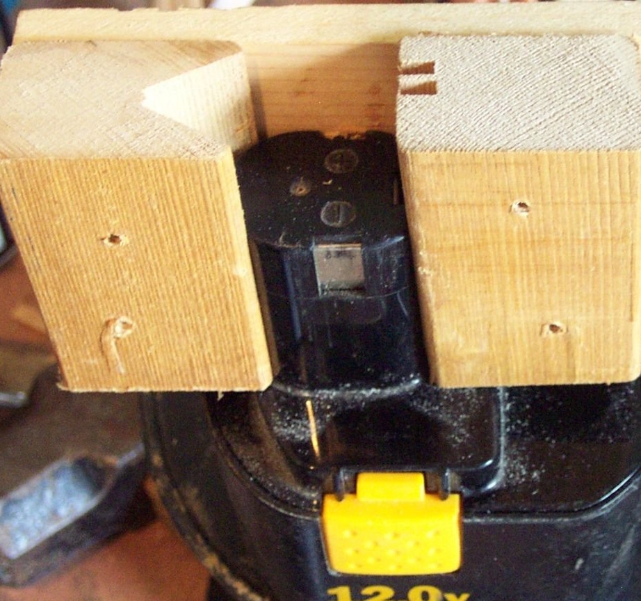
Step Four: Battery Holder Assembly
The battery holder should fit snugly against the battery pack. The contacts should touch both terminals of the battery pack.
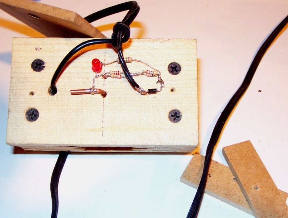
Step Five: Soldering an Electrical Circuit
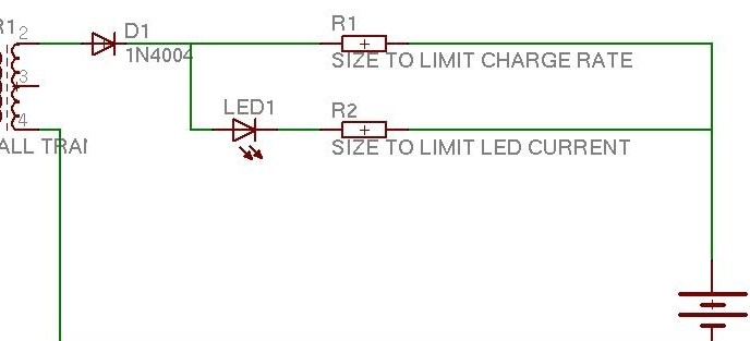

A diode, LED and several resistors are needed to ensure that the battery charges at a safe speed.
Master of this homemade Tends to a good and slow charging speed of 1/16 C (capacity divided by 16). Since he has an AC output transformer, he had to double it to 1/8. It is preferable to use 1/16 C for DC chargers, otherwise the batteries may be destroyed or light up.
Productivity 1.6 ampere-hours / 8 = 0.2A.
The nominal voltage of a fully charged nickel-cadmium cell is 1.2 V. So in a 12V battery from a screwdriver, there are 10 finger batteries. (12 V / 1.2 = 10 batteries).
The voltage of a fully discharged nickel-cadmium cell is 0.8 V. 10 batteries * 0.8 V per 1 acc. = 8 V.
20 V charger - 8 V battery = 12 V difference.
The charge level is 12 V / 0.2 A = 60 Ohms.
12 V * 0.2 A = 2.4 W of heat to be released.
2.4 W / 2 (due to AC transformer) = 1.6 watts.
The master used a set of 6 resistors to get closer to the rated 60 ohms. This gave about 3.0 watts of power dissipation when using 0.5 watts resistors. Since an AC charger is used, a power of 3.0 W is more than enough, since the resistors rest during the negative half-cycle of the AC. In reality, they deliver only 1.6 watts.
For a 20 V DC charger, the required charging speed would be 1/16 = 0.1 A and 120 Ohms. 12 V * 0.1 A = 1.2 W. Six 0.5 W resistors are also likely to be suitable for this, but the values will be different (120 ohms instead of 60).
* Be sure to do your calculations - this is just an example. *
The charge indication LED should get about 0.02 A max.
(Direct voltage drop 12V - 1.7V) = 10.3V. 10.3 V / 0.02 A = 515 Ohms. A 680 ohm resistor will be just right. LED so that the resistor does not die.
Step Six: Checking the Charging Circuit
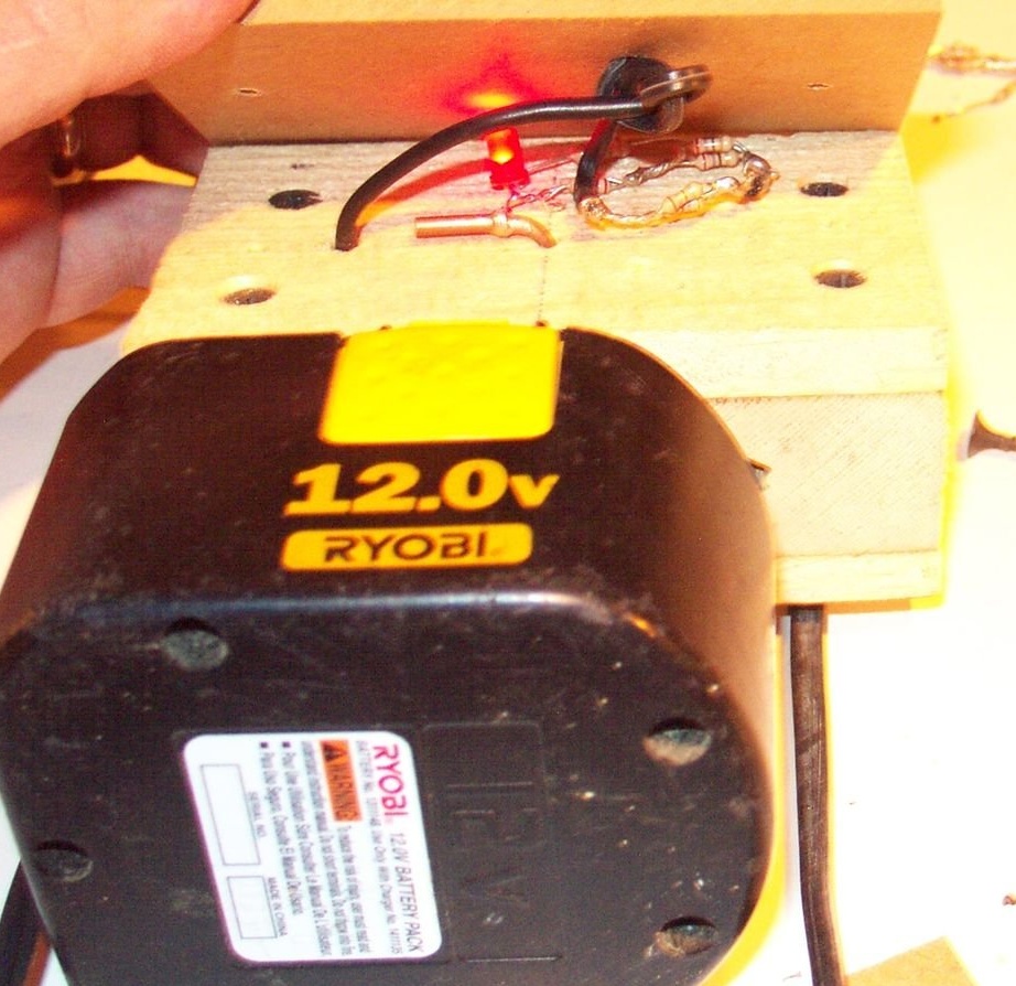
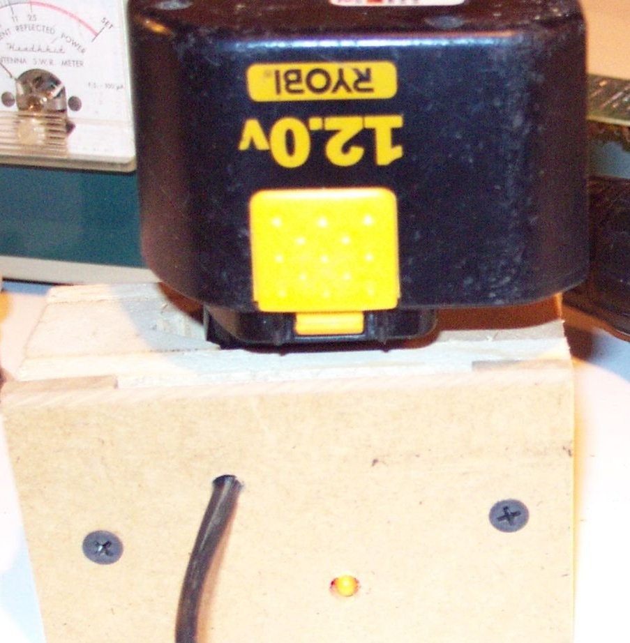
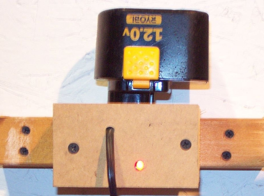
The master made a cover to close the electronics. I cut the board (plywood possible) to a size equal to the sides of the battery holder. He pulled the cord from the transformer through the board and soldered to the electrical circuit.
Also drilled a hole for the LED. When the plug is plugged in, the LED should light up.
Step Seven: Hiding Electronics
After making sure everything works, it's time to close electronics. Cut the two gasket strips so that the cover does not break the electronics. The author used a thin piece of fiberboard. Drill holes in the board (or plywood) and spacers at the same time.
Step Eight: Final
Tighten the last screws and try to charge the battery.
The master also screwed a wooden block to the wall, on which he fixed the charger. Now both batteries will be ready to work when they are needed.