

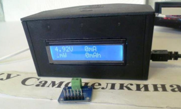
After converting the screwdriver to lithium, the idea arose to make a charger similar to factory models with measuring current, voltage and battery capacity. Actually for this you need a power source, a battery charge board based on the CC CV principle and a parameter display module. Let us dwell on the display module of the above parameters. This module will make it possible to measure the actual capacity of a rechargeable battery (or battery assembly).
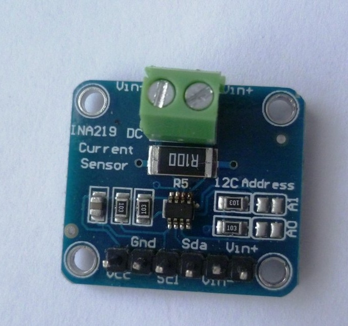
The basis of the display module is a voltage and current sensor type INA219 purchased at Aliexpress. This shawl is designed to measure voltage values up to 26 V and current values up to 3.2 A. All measured parameters are transmitted via I2C to Arduino. This sensor determines several parameters at once: power and capacity in mA \ h, current and voltage.
Characteristics of the INA219 Sensor.
1) The limits of the measured voltages: from 0 to 26 V;
2) Sensor supply voltage: from 3.0 to 5.5 V;
3) Parameters for the measured current - maximum 3.2A;
4) The accuracy of measurements of voltage and current up to 1%.
The INA219 sensor does not require additional strapping, it is enough to supply power to the sensor itself, connect the power plus and minus wires and connect via Arduino to the I2C interface. You can use the module in circuits where you need to control data during charging and discharging batteries. You can also use the INA219 sensor in power supplies as a voltage and current monitoring unit for connected consumers.
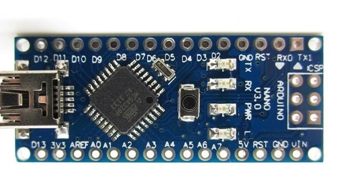
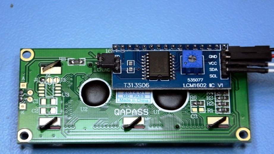
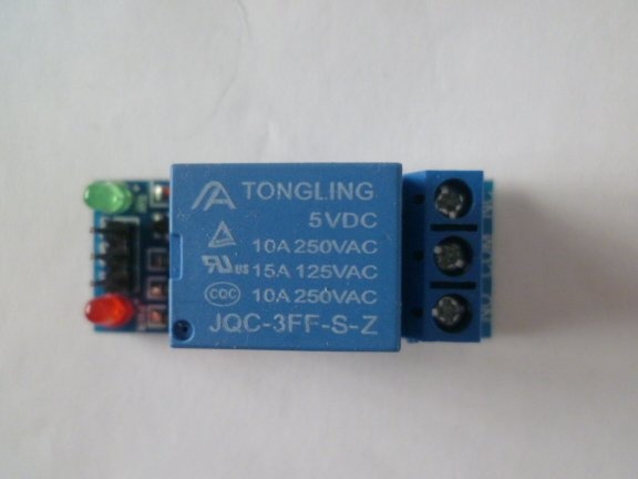
The device itself will include the INA219 sensor itself, the board Arduino (you can use any option - Uno, Nano, Pro Mini), a two-line LCD1602 screen with an I2C interface board, a 5V relay module.
Enumeration of tools and materials.
-Payment Arduino Nano-1pc;
Sensor INA219-1pcs;
- two-line LCD1602 display with I2C-1pcs interface board;
- relay module for 5volt-1pc;
- Charger from the phone to power the circuit-1pc;
-connecting wires;
soldering iron;
-tester;
plastic distribution box -1pcs;
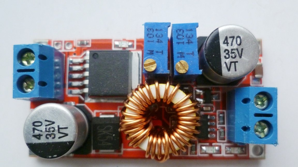
- lowering board 5A -1pcs.
Step one. Assembly of the display unit on the INA219 sensor.
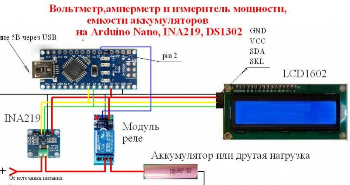
We assemble the device diagram using wires with connectors. Input and output power wires through which the load will be fed, we take a section of 1-1.5 kV, mm. The circuit modules will be powered from the charger from the phone via the USB connector of the Arduino Nano board, and then from the +5 and Gnd contacts.The communication of the INA219 sensor with the Arduino via the I2C interface goes through the CLK and SDA terminals. The address of the INA219 sensor can, if necessary, be changed by soldering the contacts A1 and A0. Very carefully and carefully assemble the sensor circuit with your V + contacts, V- must be connected in series with the load, also INA219 does not like polarity reversal. Without observing these requirements, you can easily disable it!
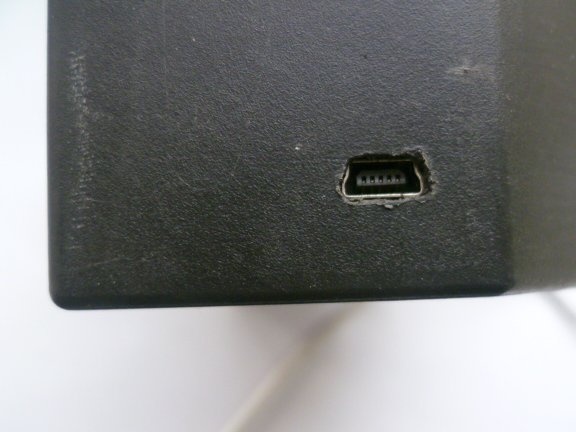
In the distributor box case, cut out a window for the LCD1602 display, at the bottom we make a hole for the USB connector of the Arduino board.

Step Two Device programming.
You need to install the library for the INA219 sensor. It is in the IDE arduino. Click “Sketch”, then “Connect the library” then “Manage libraries”. In the search line, type "INA219". Finds Adafruit INA219 by Adafruit version 1.0.3 "install.
Download the sketch.

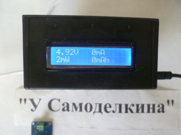
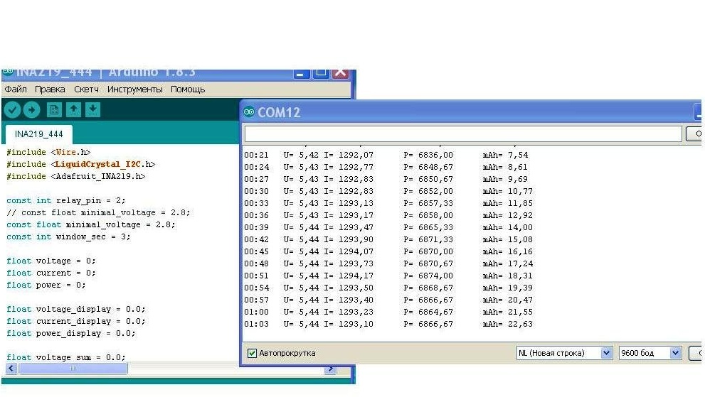
Usually, the appliance starts working immediately. In the port monitor you can see all the measurement data.
Photo port monitor
Step Three Checking the health of the device.
Without load, the device displays current voltage values. We connect the load and on the display we see the values of voltage, current, power consumption and capacity. If you need to charge lithium batteries, you must use the CC CV board. It will make it possible to regulate both voltage and charge current. . This scarf can be placed with others. Then in this case, you get a complete device for charging such batteries.
To determine the battery capacity, you need to connect it as a source in front of the INA219, and connect a load (for example, a car lamp) to the output wire. In the sketch, the lower load disconnect limit is set at 2.8 volts. The value must be selected according to the datasheet of your batteries. When the voltage reaches 2.8 Volts, the relay will disconnect the load and on the display we will see the actual battery capacity in milliampere hours. To turn the device back on, you need to reset the 5 Volt power to Arduino or install the reset button on the RST pin of the Arduino and GND boards.
Of this homemade You can determine the capacity of a single battery as well as assemblies of several batteries (battery pack for a screwdriver).
More details can be seen in the video
Readers of the site all the best in creativity and in life!