
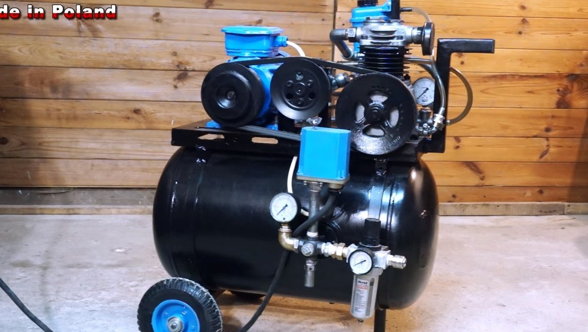
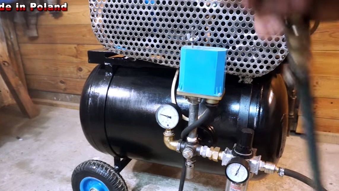
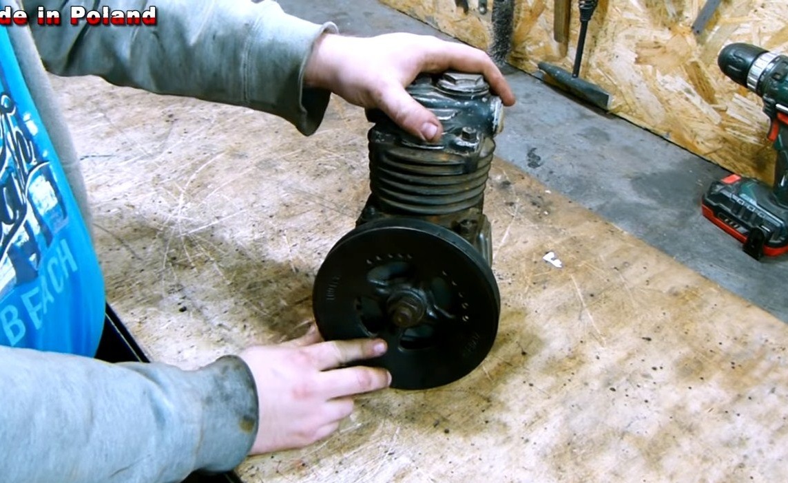
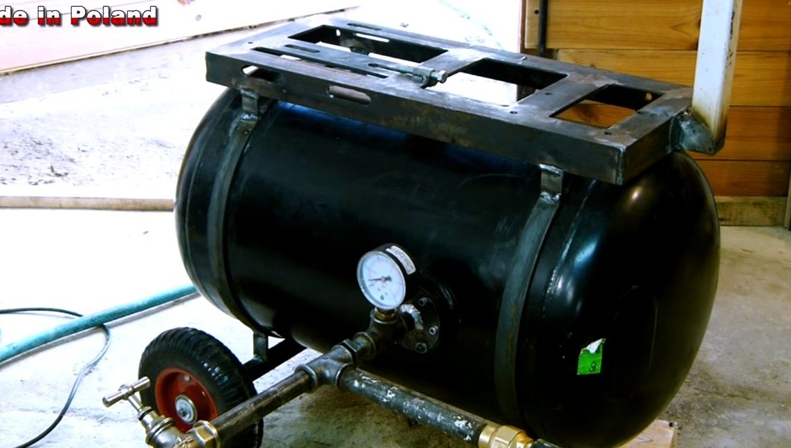
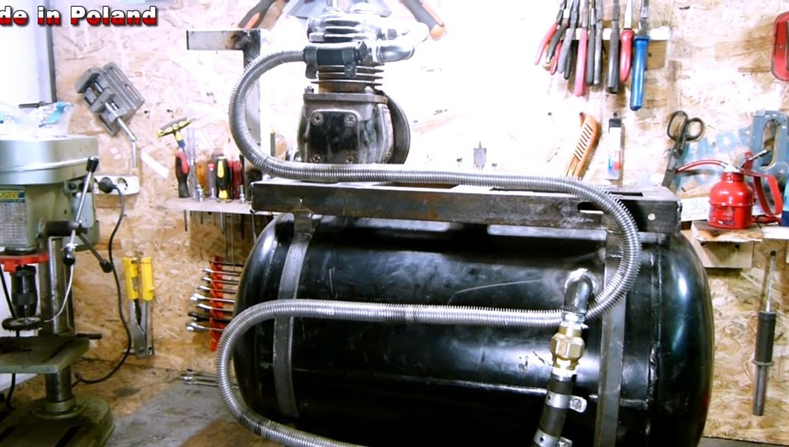
Hello everyone, in this instruction we will look at how to make a powerful do it yourself. Fabricated homemade equipped with a 60 liter receiver. This cylinder is capable of withstanding pressure up to 30 bar.
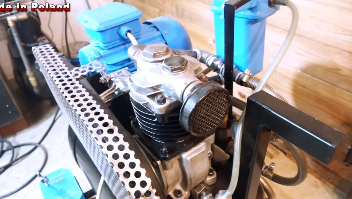
As for, the author used the unit from a truck, it is powered by a three-phase engine of 3 horsepower. An interesting fact is that the system is equipped with forced lubrication of the compressor under pressure, the car pump from the power steering is responsible for this. If you are interested in the project, I propose to study it in more detail!
Materials and tools used by the author:
Material List:
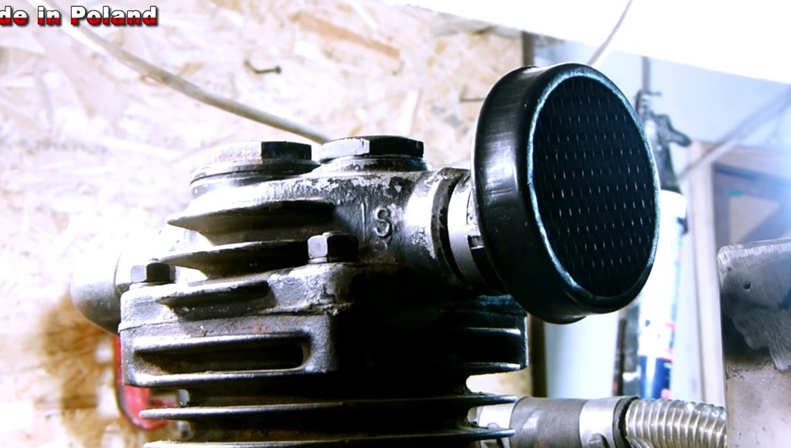
- An old compressor from a truck;
- three-phase 3 hp engine or similar;
- pulleys, belts, wiring, switches, etc .;
- automobile gas cylinder or other similar container;
- sheet steel, profile pipes, corners;
- wheels for garden carts and axle;
- tubes, hoses, fittings, pressure gauge, filters, etc.
- Car steering booster pump (author's from Audi 80);
- screws, nuts, fum tape and more;
- mesh (to make a protective shield);
- paint.
Tool List:
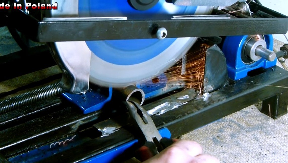
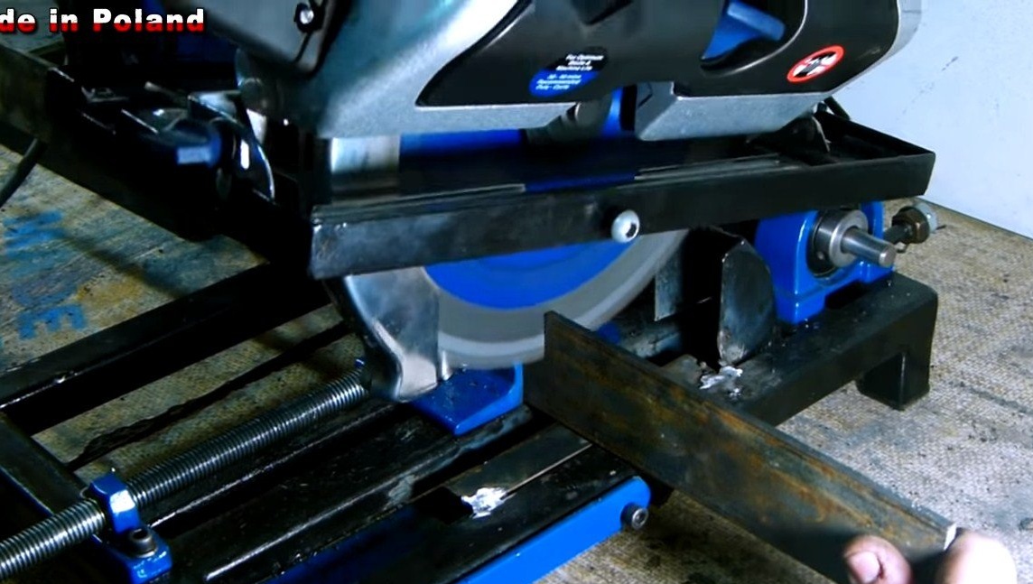
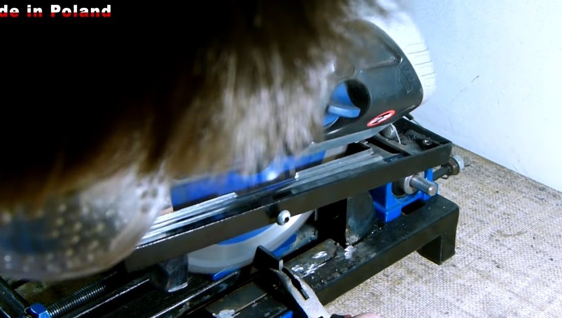
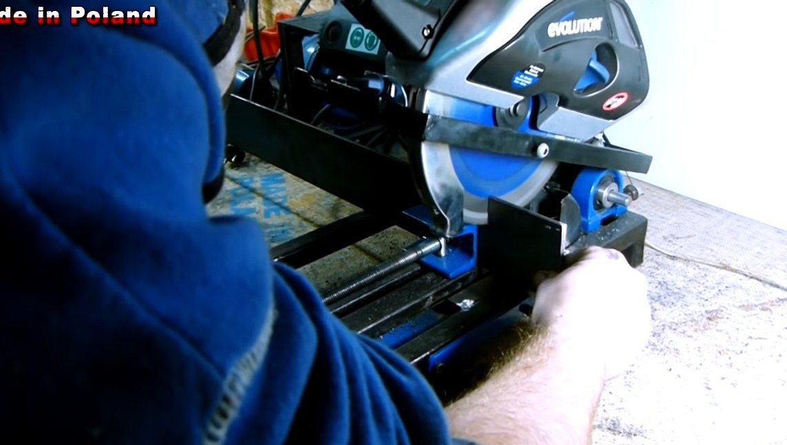
- Miter saw;
- grinder;
- welding;
- screwdriver;
- drill;
- vise, wrenches, etc.
Compressor manufacturing process:
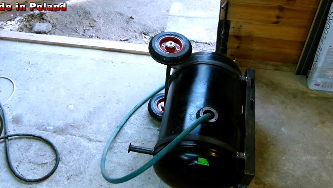
Step one. We install wheels on the tank
We install wheels on the tank so that this weighty machine can be transported. To do this, we install reliable steel clamps on the tank and tighten them with bolts and nuts. It is to these clamps that we will then attach all the necessary equipment.
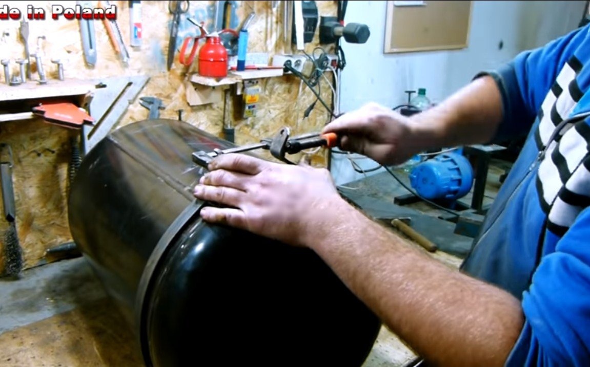
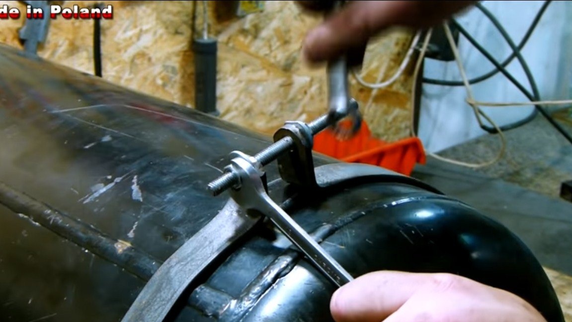
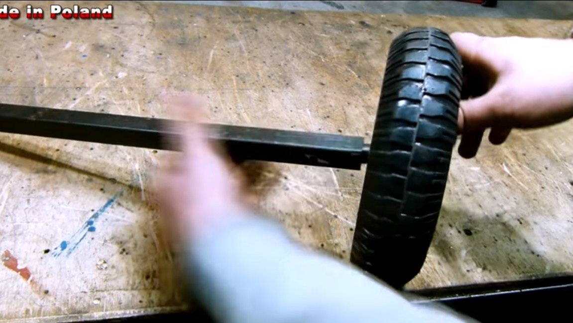
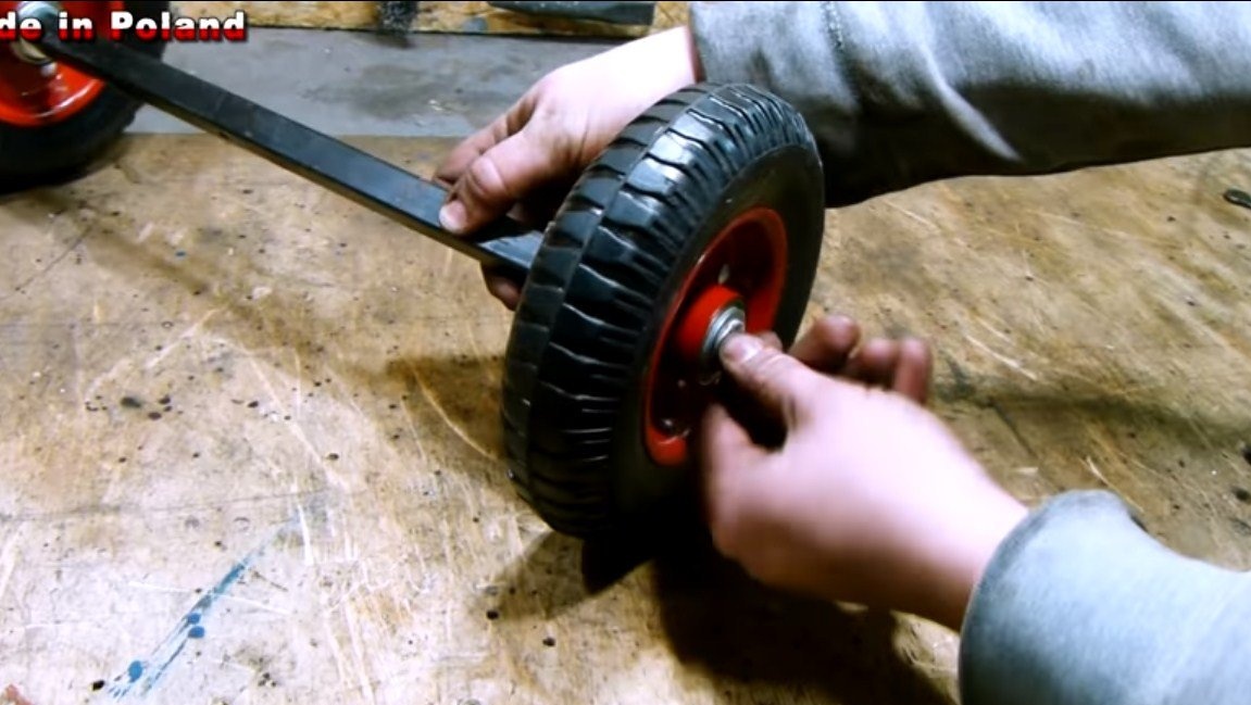
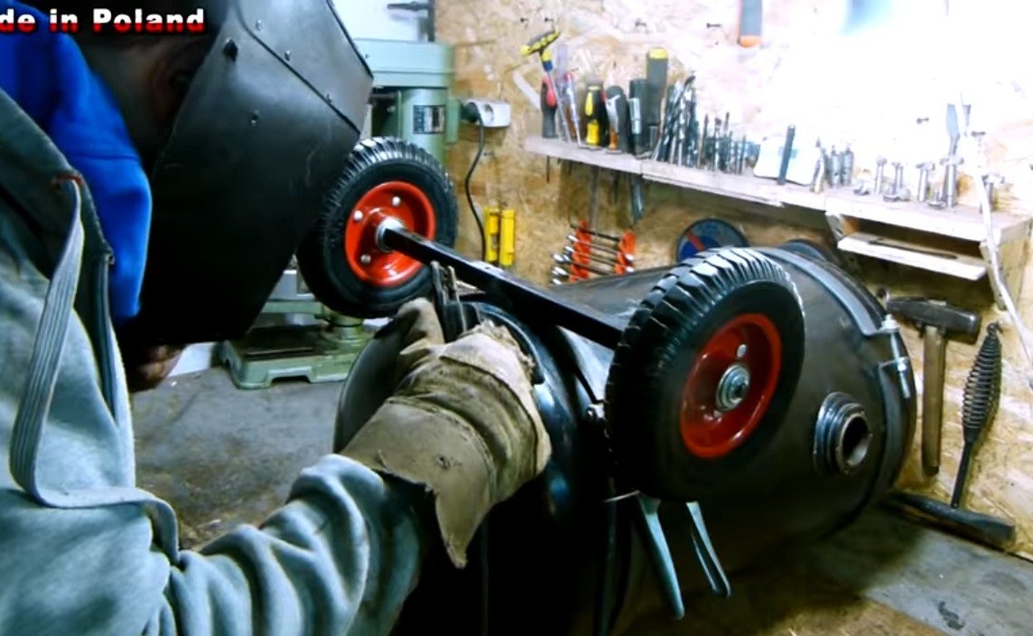
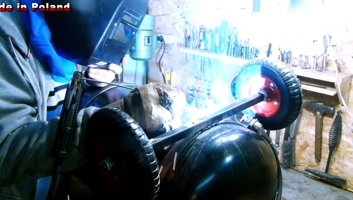
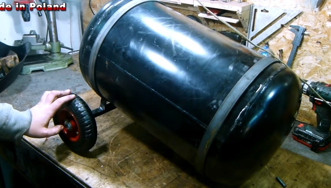
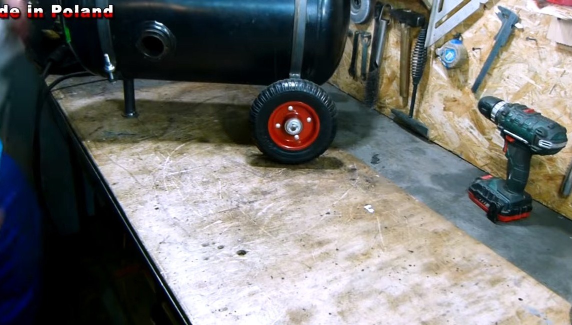
When the clamps are installed, fasten the axle with wheels. As an axis, we use a rectangular profile pipe to which round axles for wheels are welded. We choose stronger wheels, with steel discs and bearings, since the weight of the device is quite large.
We also need to weld a leg in front of the machine, it is made from a piece of pipe to which a nickel from sheet steel is welded.
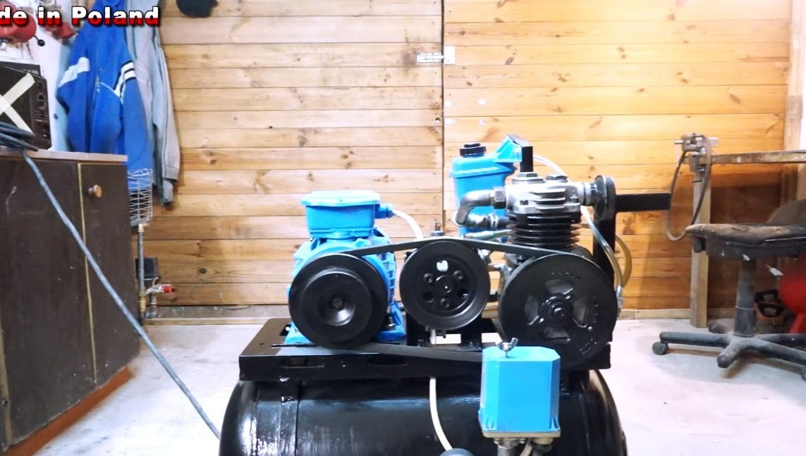
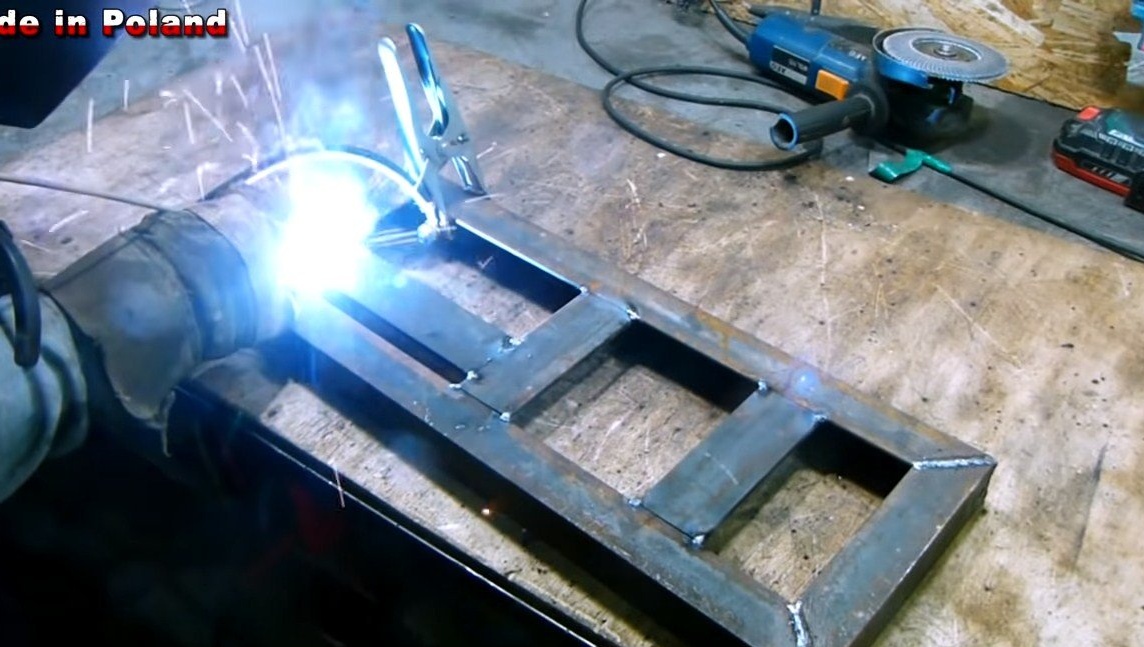
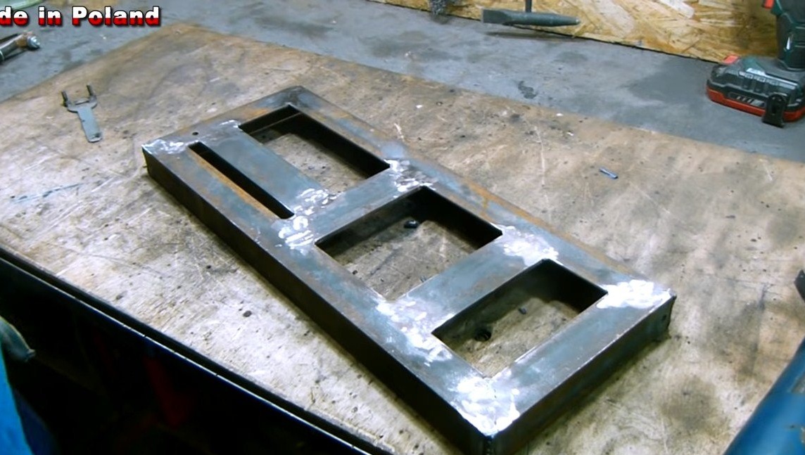
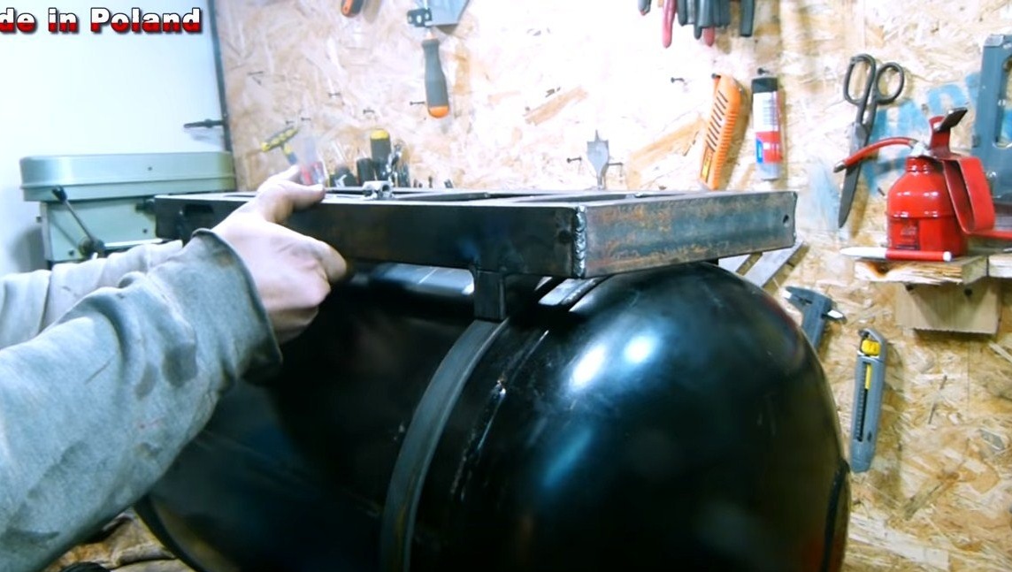
Step Two Making frames for equipment
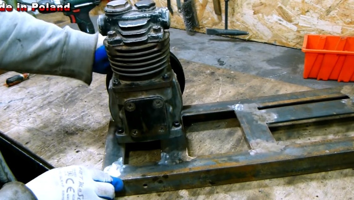
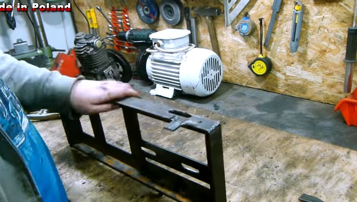
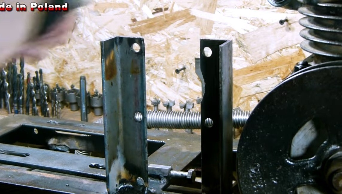
The compressor, as well as the engine will be installed on top of the receiver, they will be attached to the clamps. We make the frame from the corner, as well as sheet steel. We drill holes for the compressor and cut the threads, we will fix it to the frame statically with screws.
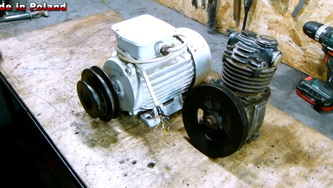
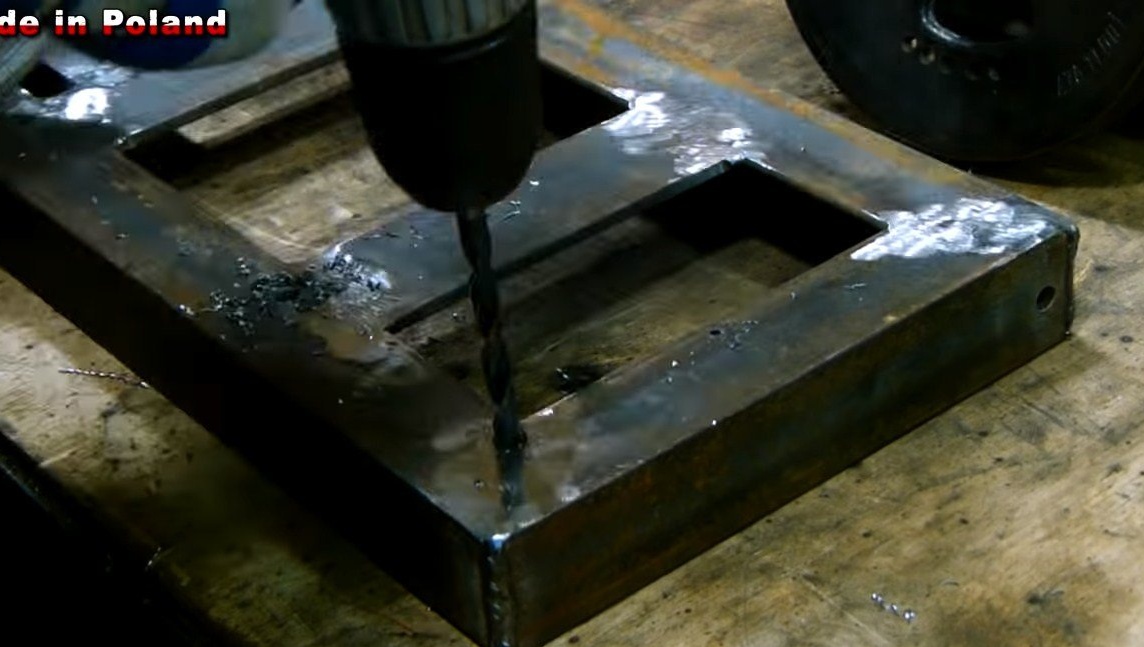
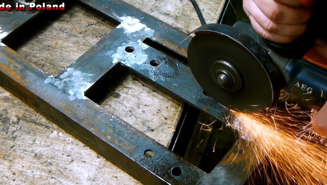
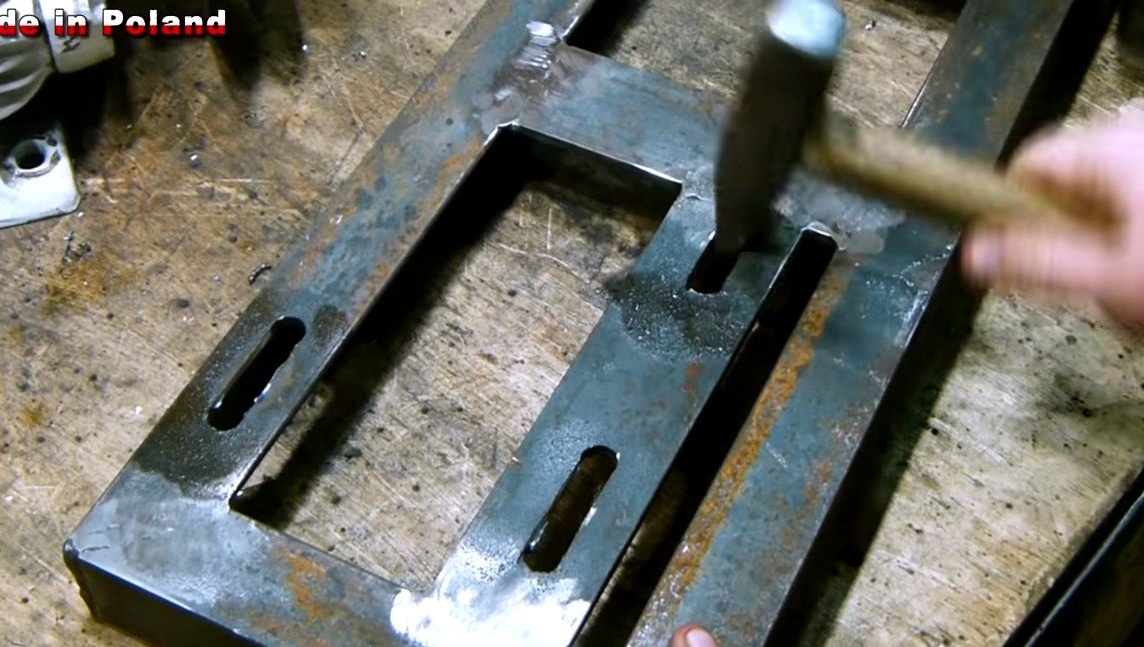
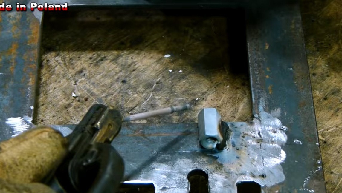
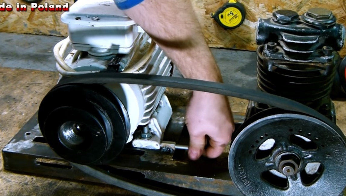
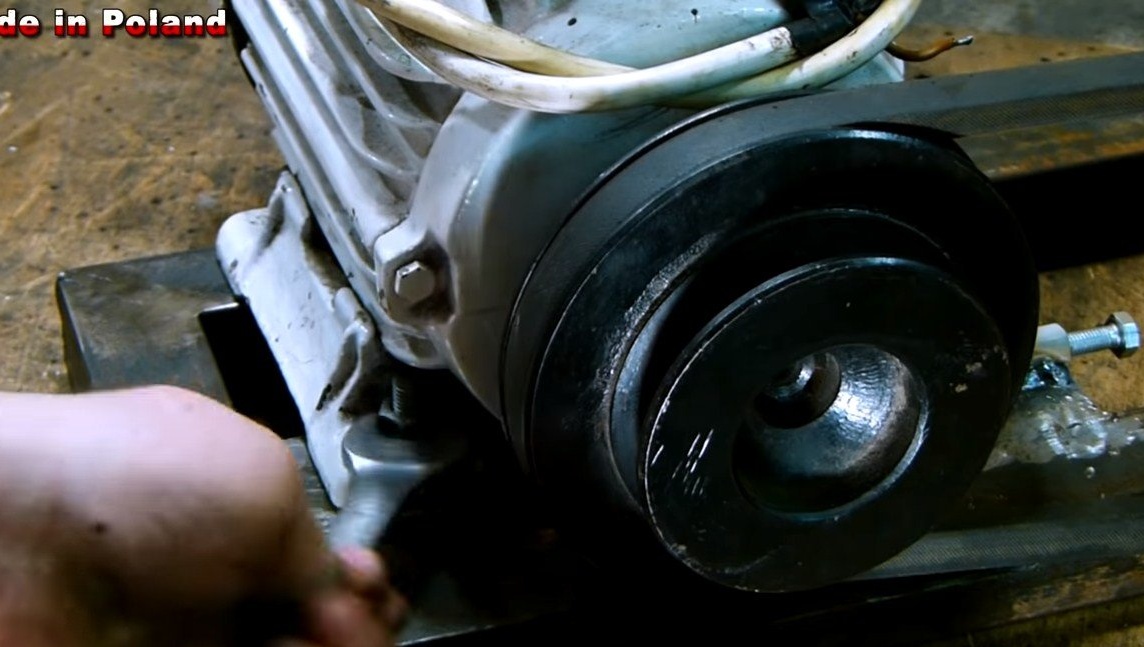
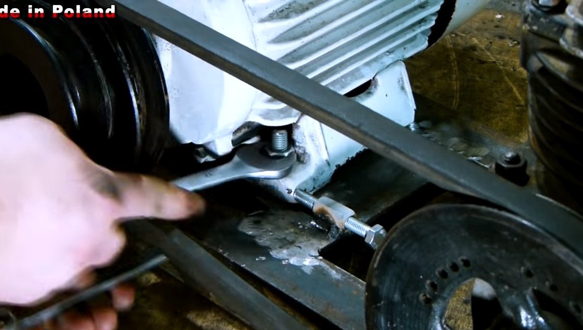
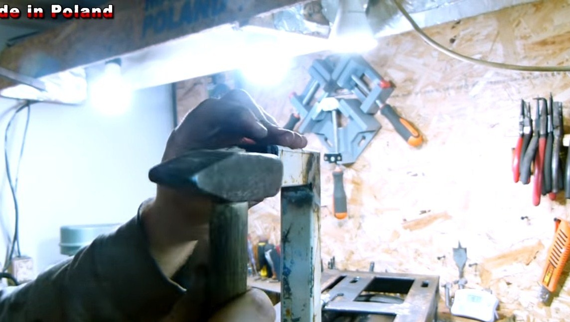
As for the engine, it should be able to ride along the frame so that the belt can be pulled. We drill holes, and then combine them with a grinder to make slotted holes.As a tensioning device, we weld an extended nut to the frame and wrap the bolt. Now, by tightening the bolt, the engine can be pulled back and the belt pulled.
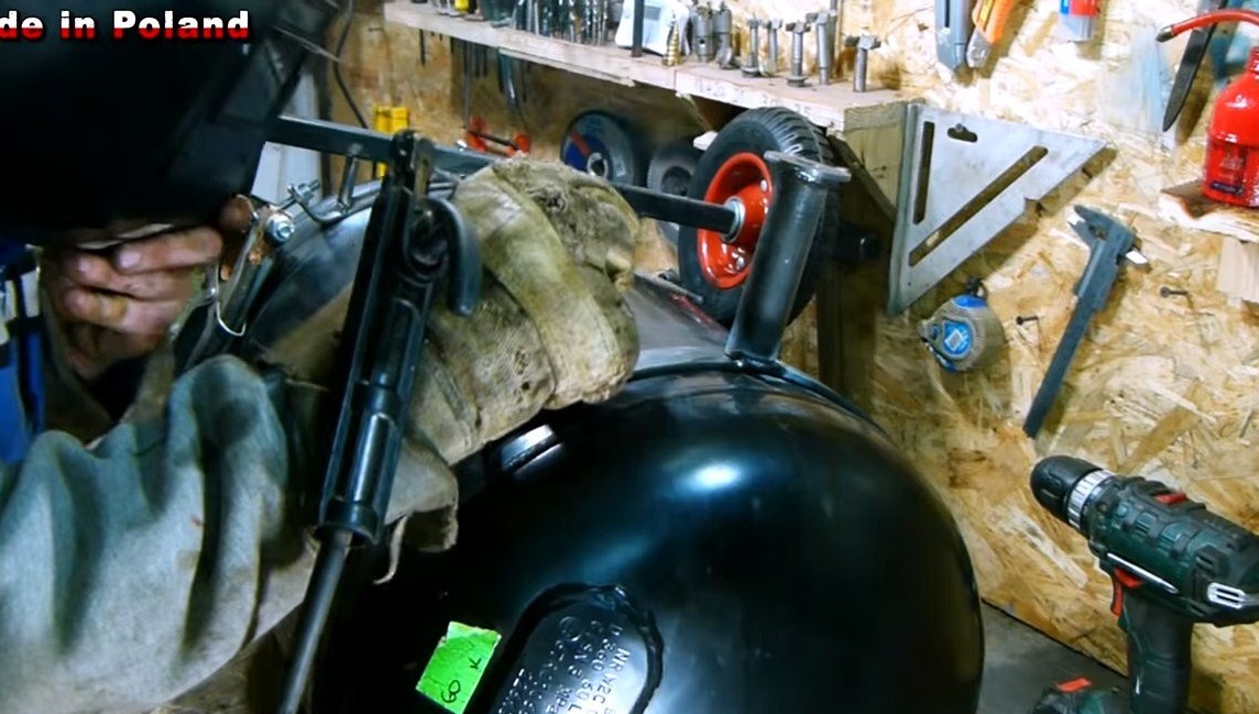
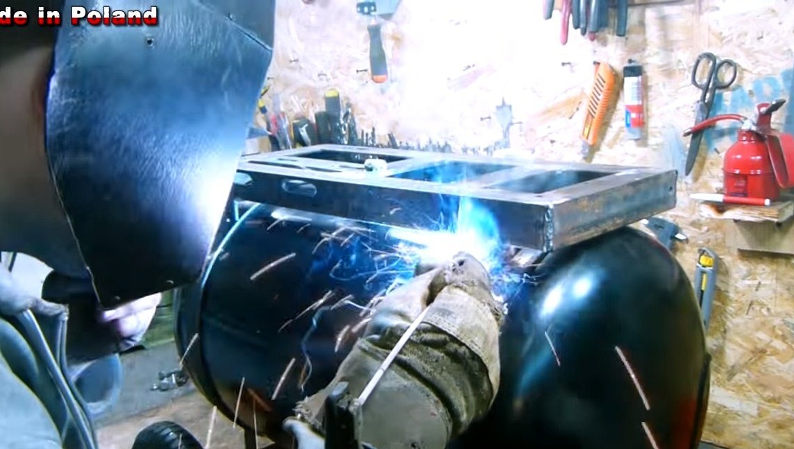
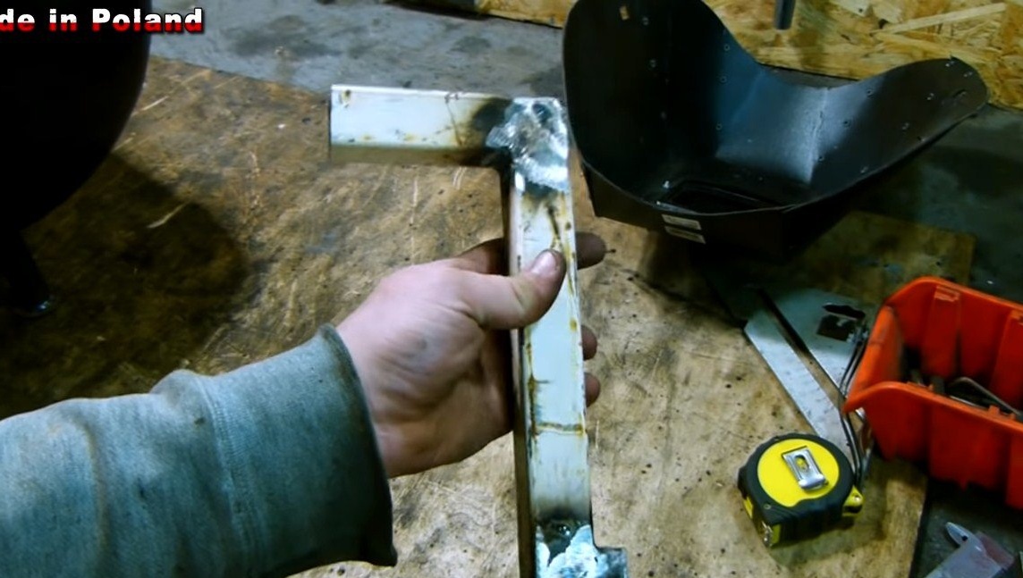
We weld pieces of steel plates to the frame and then install the frame on top of the receiver. You can also weld a handle to the frame so that there is, for what, a compressor, the author has welded it from a profile pipe.
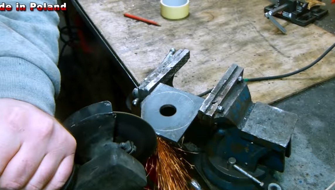
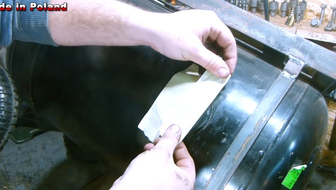
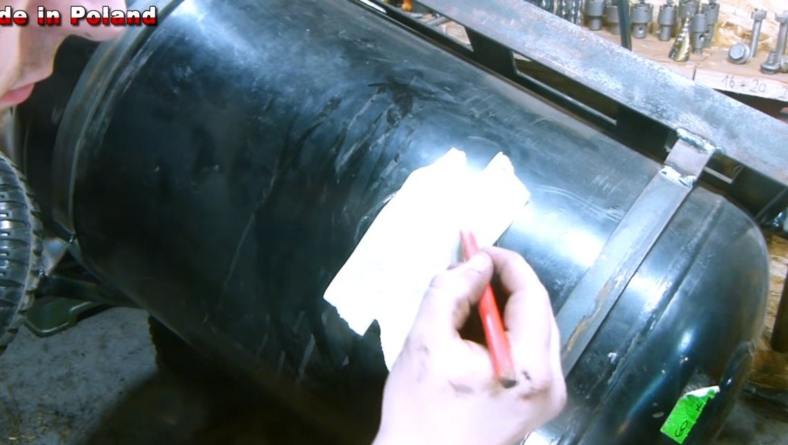
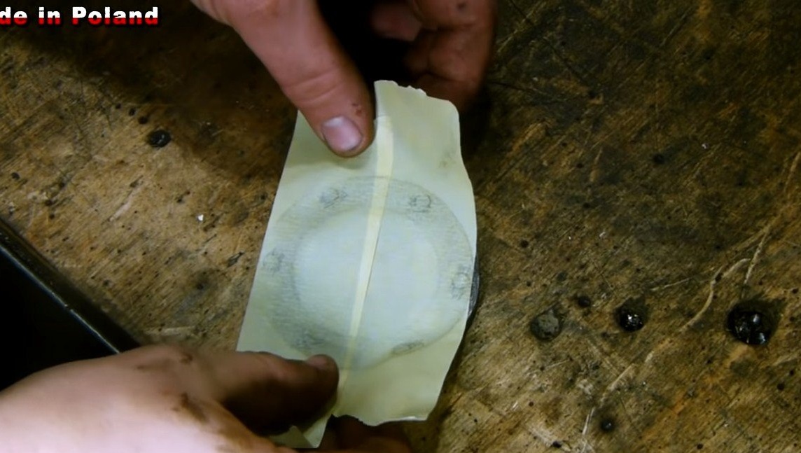
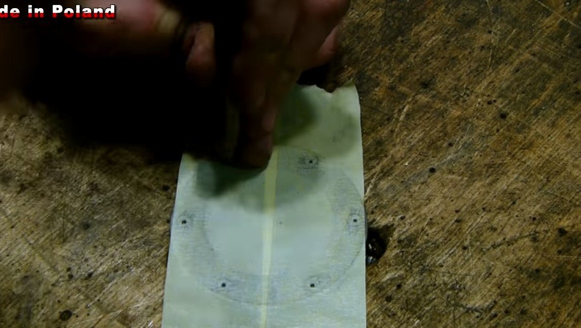
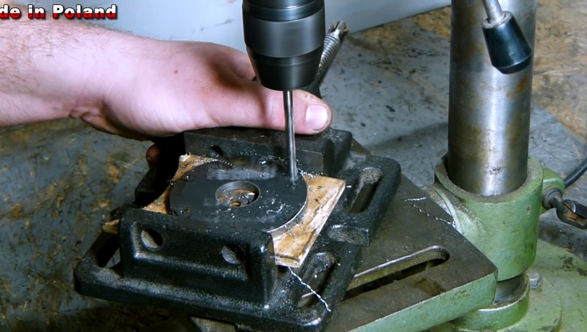
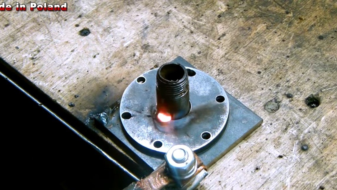
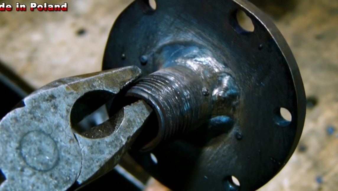
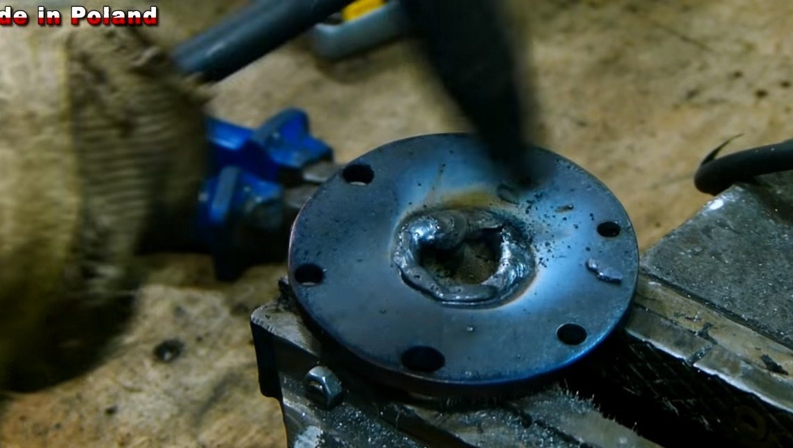
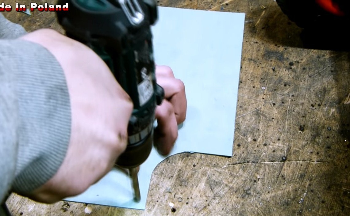
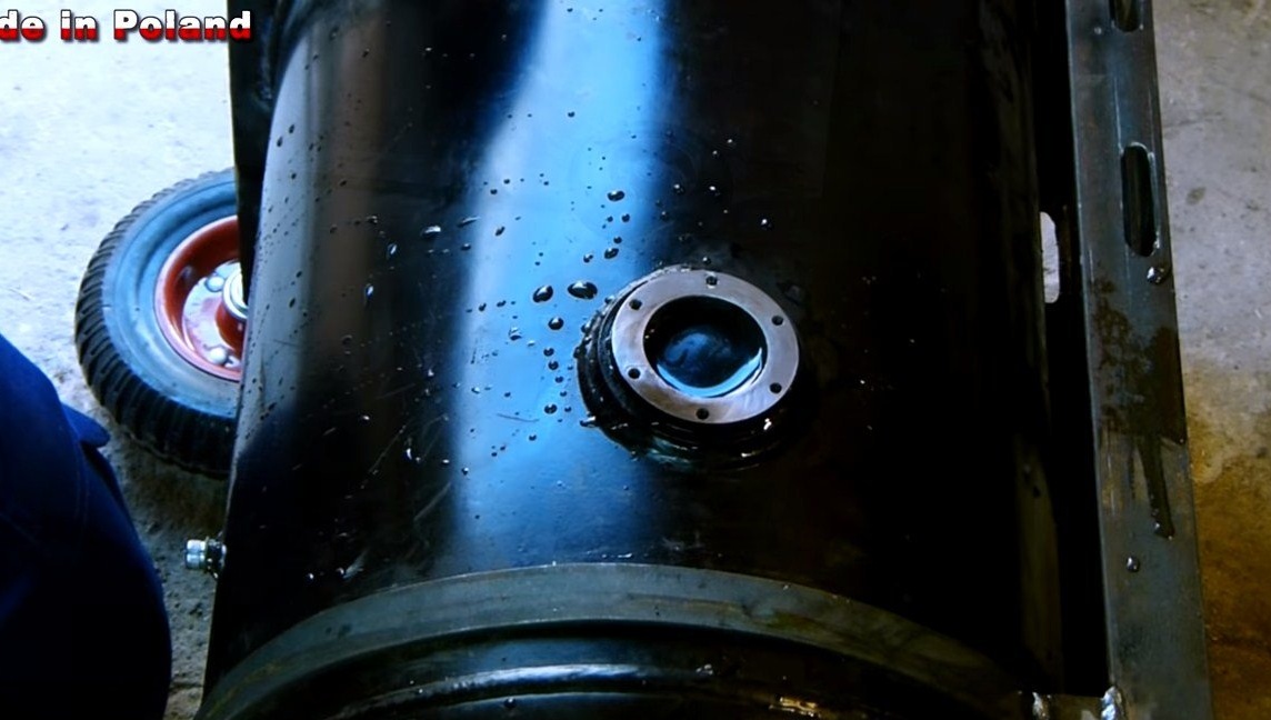
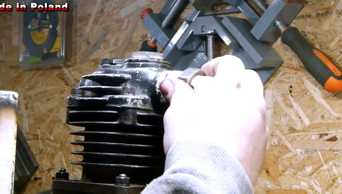
Step Three Adapter
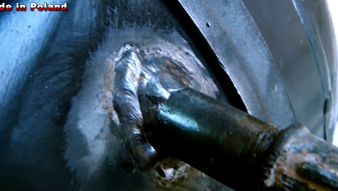
The cylinder has a hole of large diameter, here you need to make an adapter, the author made it of sheet steel. We put a piece of paper to the hole and use a pencil to find where to drill the holes. Well, then it’s a matter of technology, we cut the workpiece, drill holes and weld the pipe. It is very important that the weld be strong and tight.
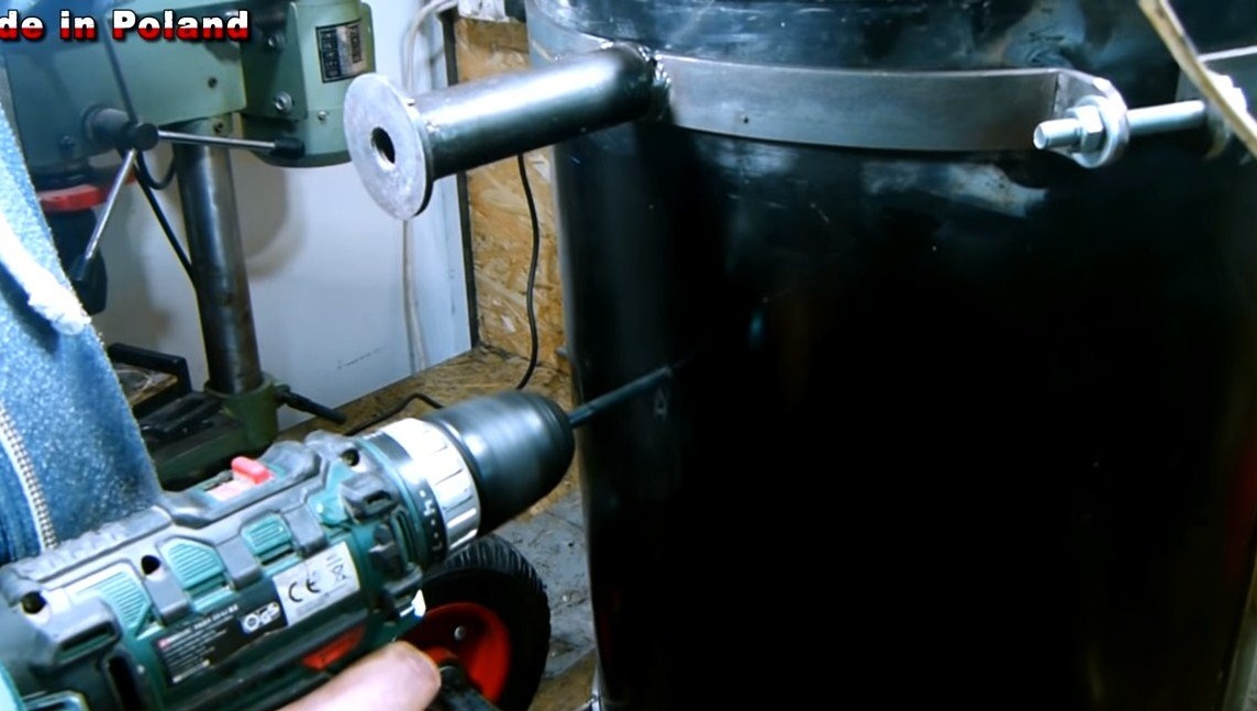
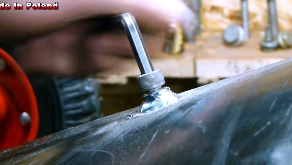
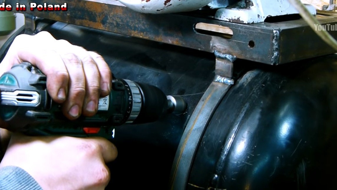
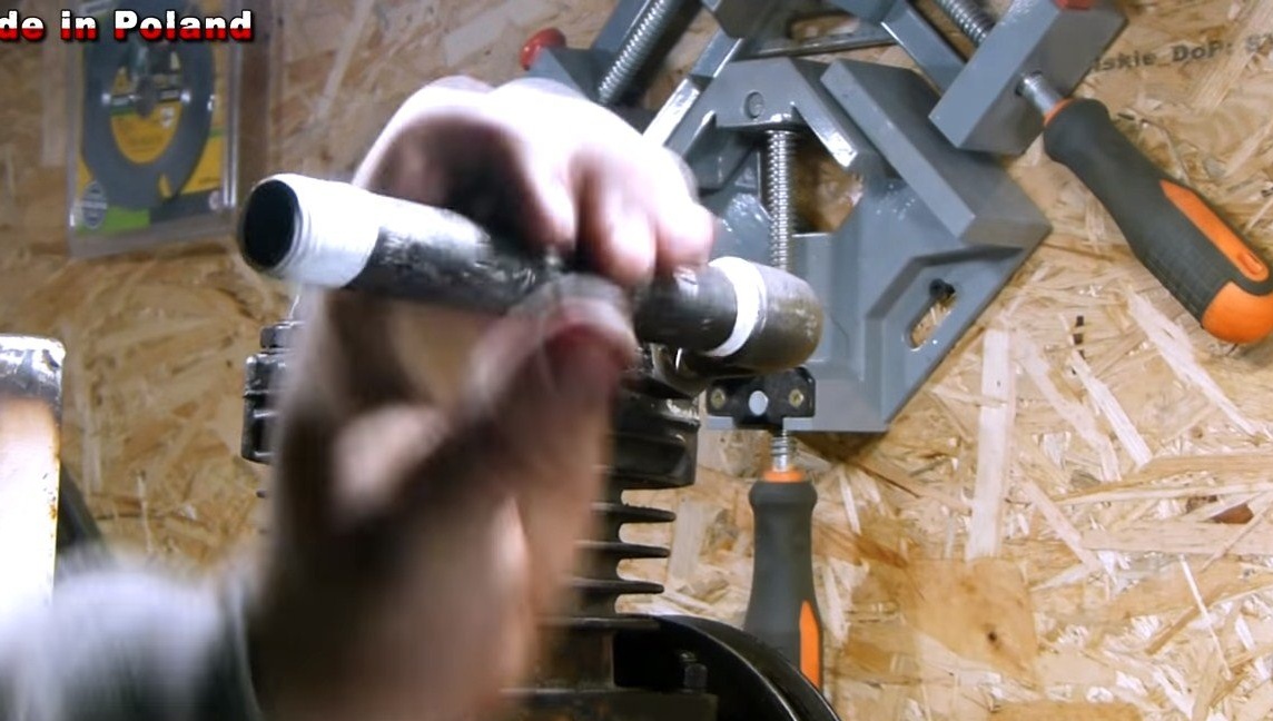
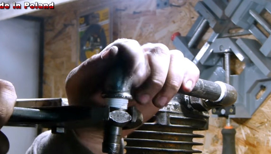
Step Four Drain and Inlet Pipe
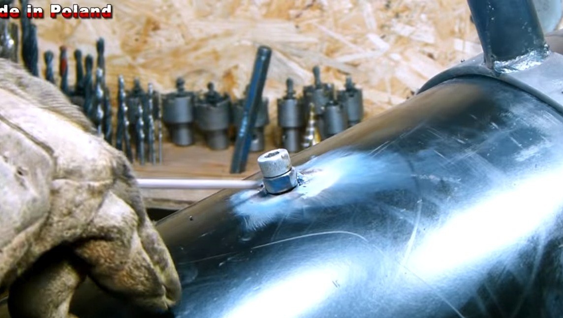
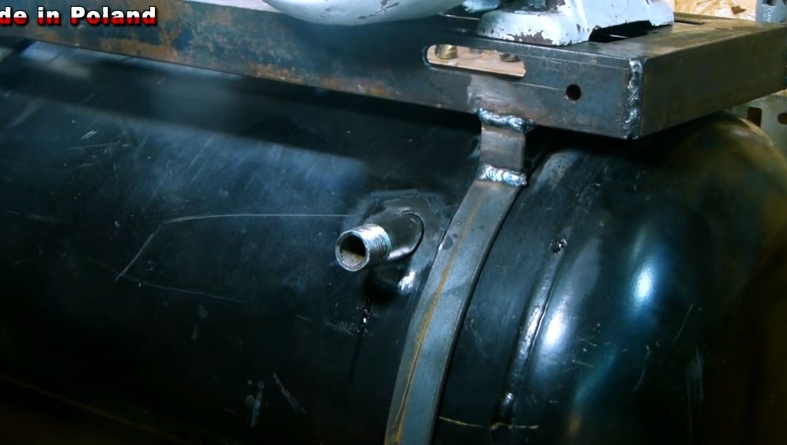
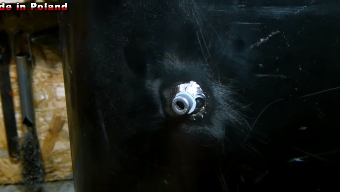
In the "belly" of the receiver, drill a hole and weld a nut. As a "crane" will use a conventional screw. This part is needed in order to drain the condensate from the receiver, which will eventually form there over time.
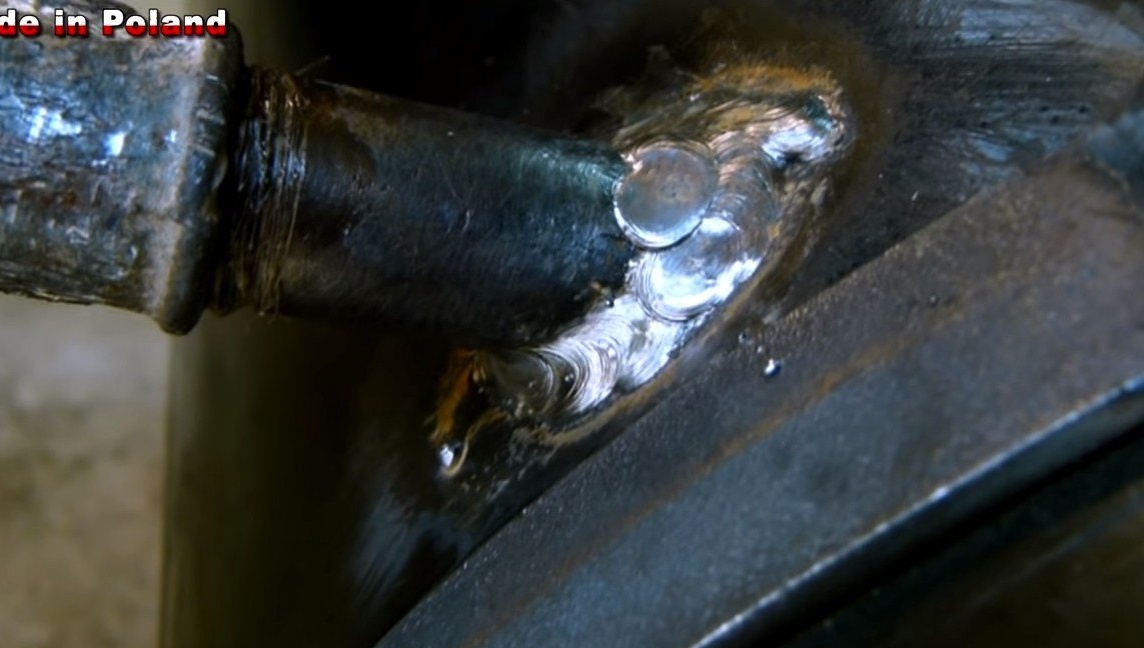
Next, you can drill a hole and weld the inlet pipe into the cylinder. Of course, everything here should also be tight and tight.
For the drain screw, a gasket must be made.
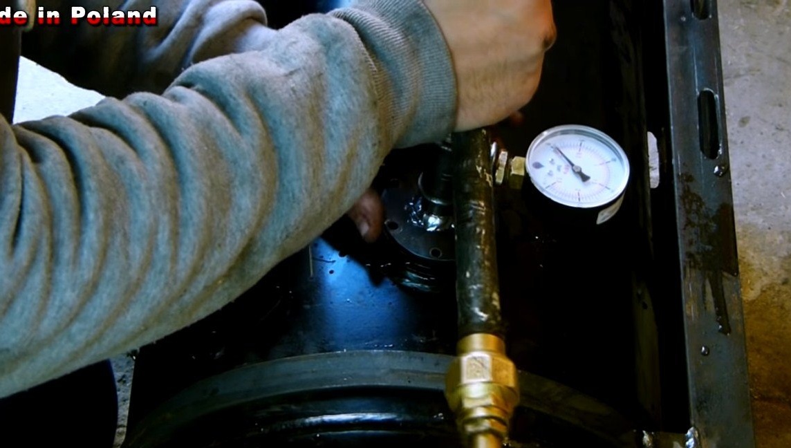
Step Five Leak test
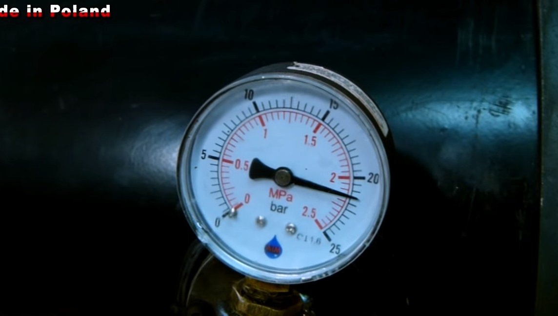
To check the tightness of the container, the author poured water into it, and then created a pressure of more than 20 bar. If at this pressure no leakage is detected, then the cylinder is assembled very reliably. It is important to inspect all welds and the drain screw; it should be dry in these places.
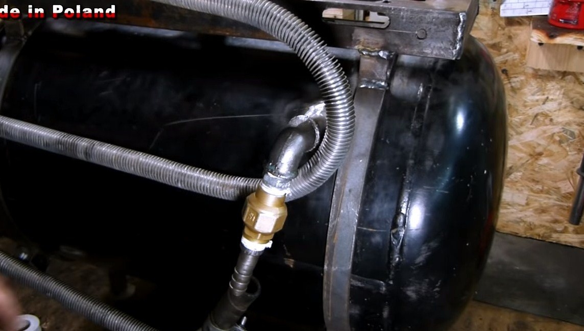
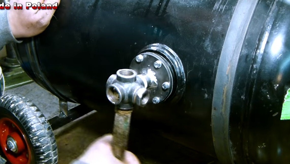
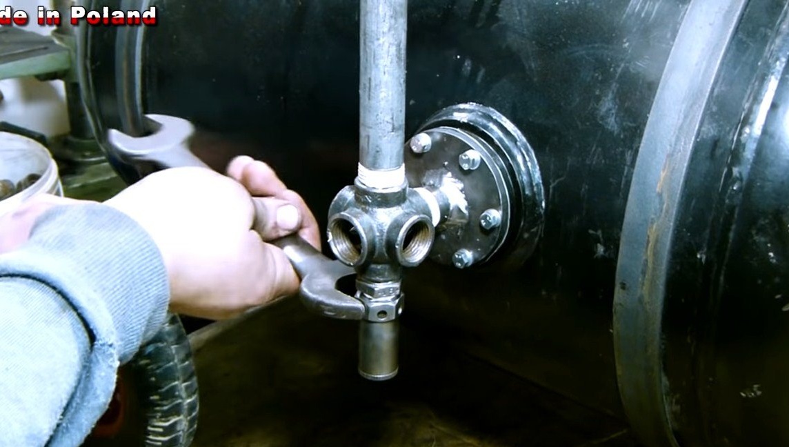
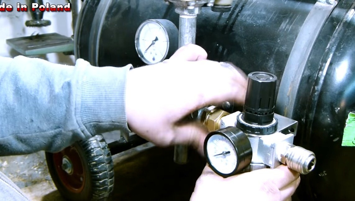
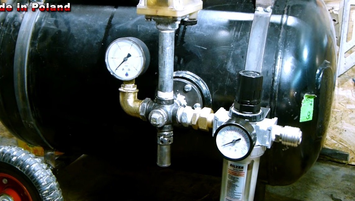
Step Six Equipment connection
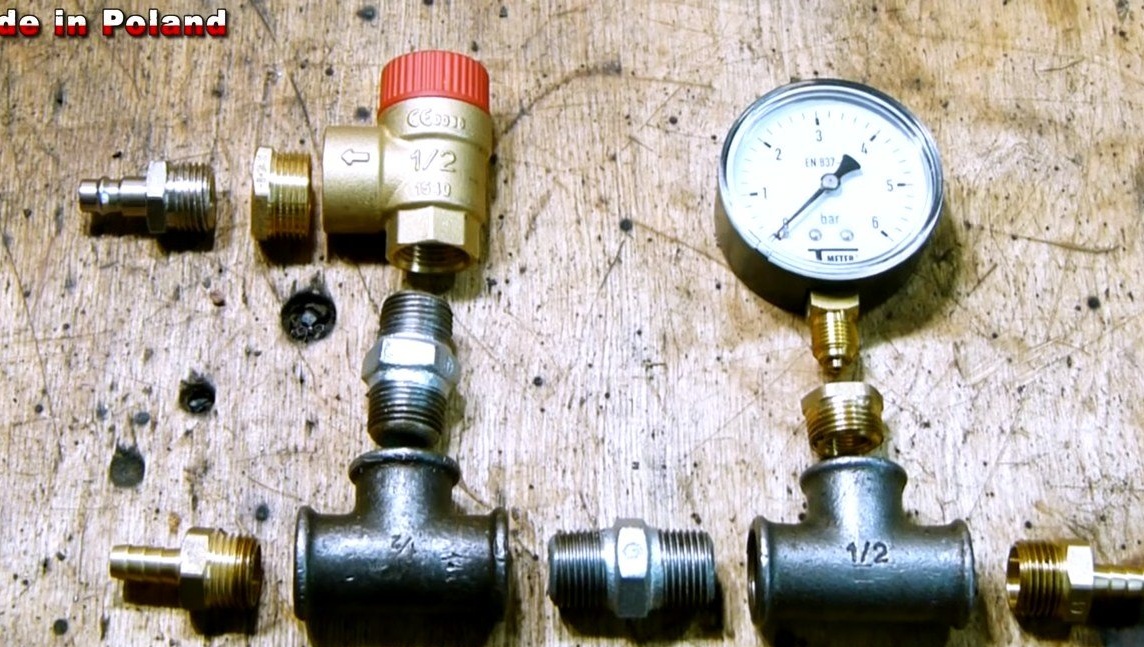
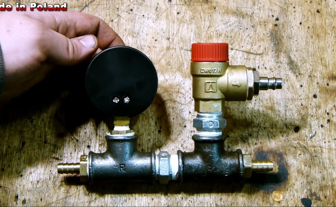
Next, we connect the hose to the receiver from the compressor, and also screw the splitter into the cylinder to connect the selected hose, pressure gauge, valve, and so on. All threaded connections are carefully insulated with fum tape.
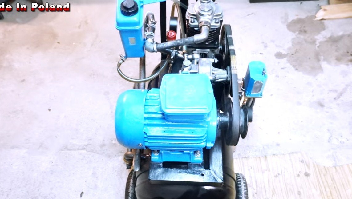
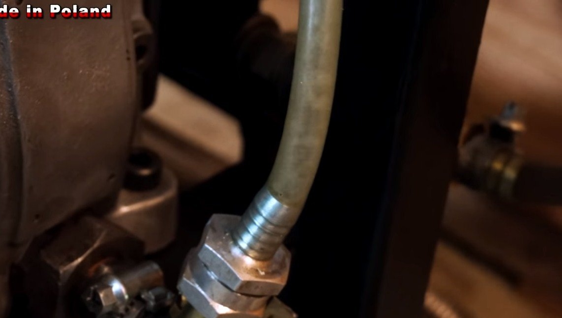
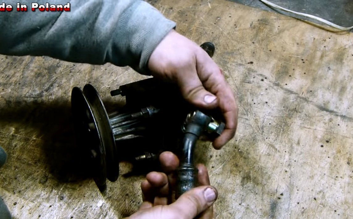
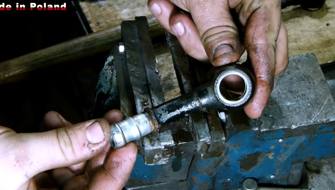
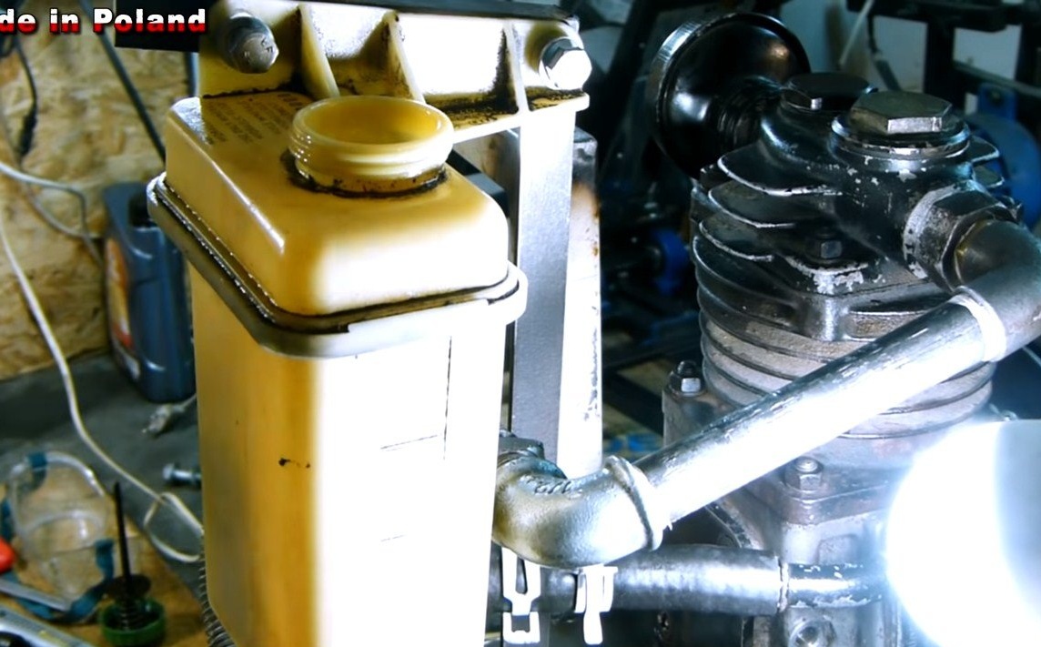
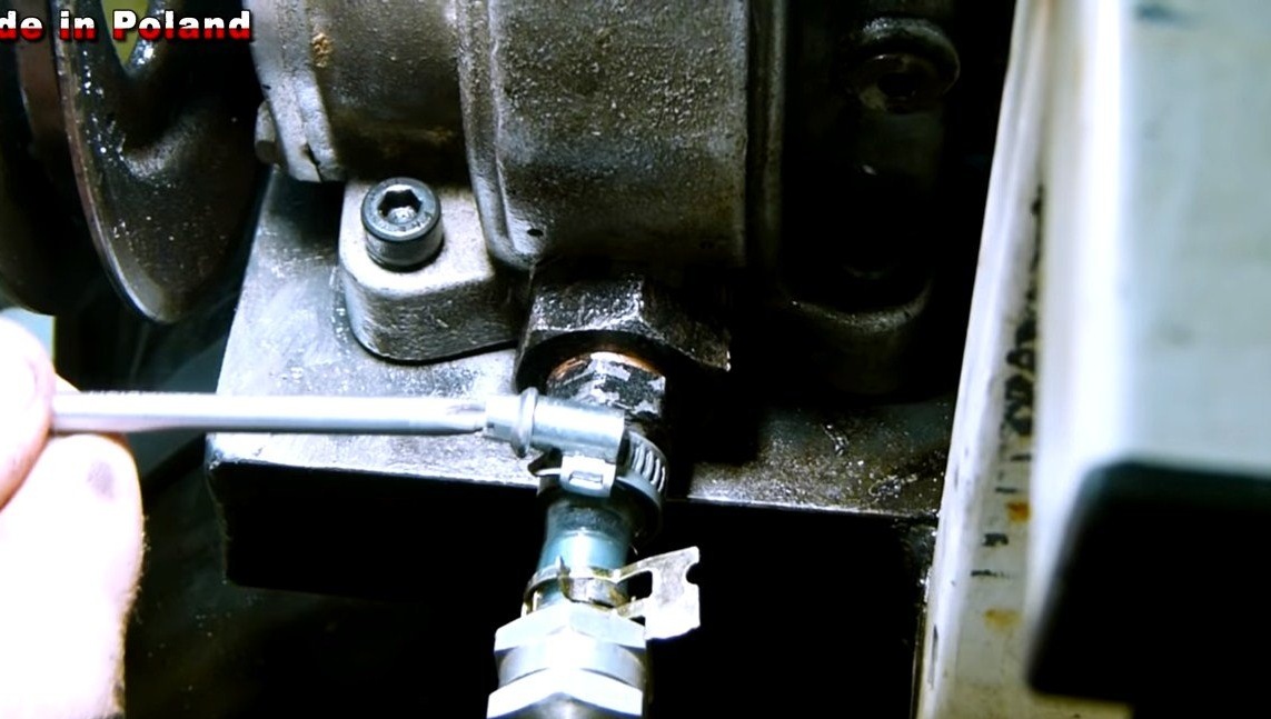
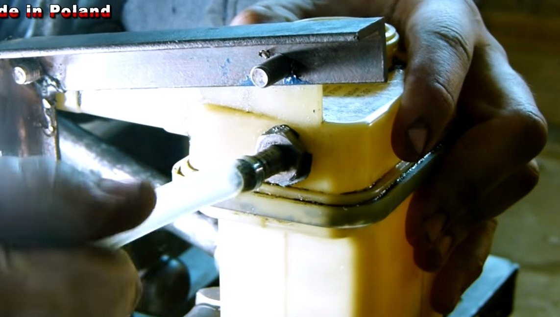
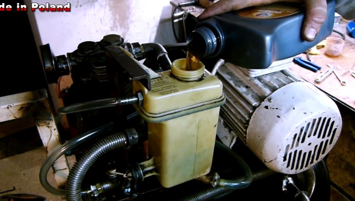
Seventh step. Lubrication system
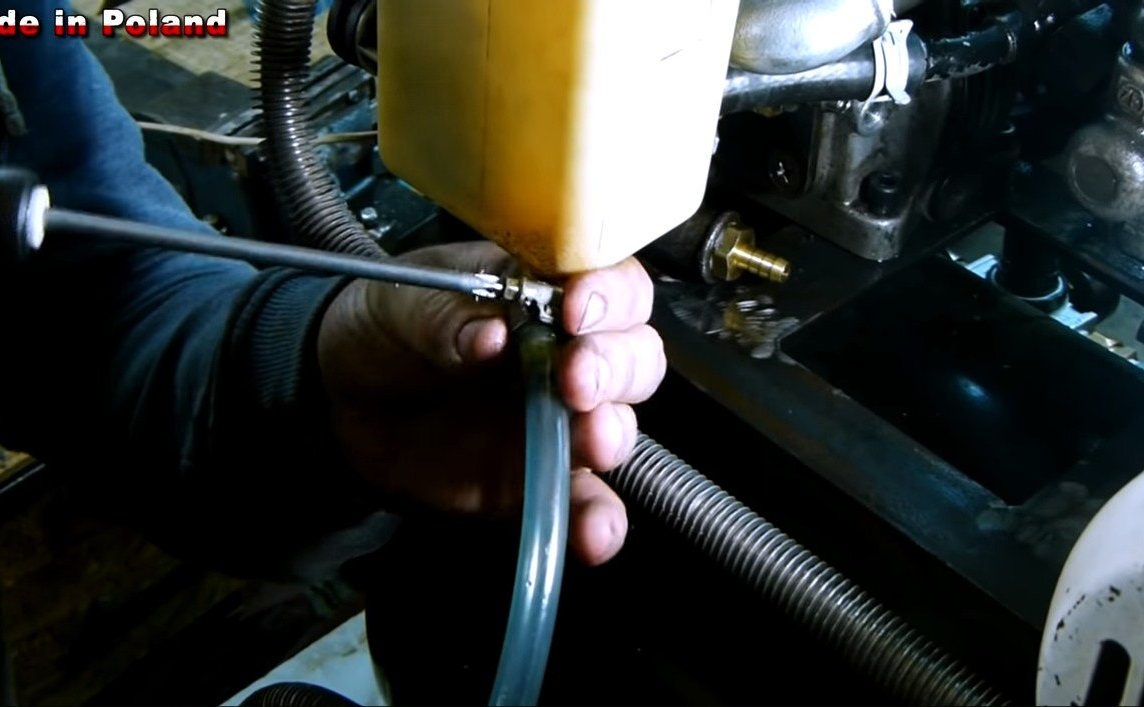
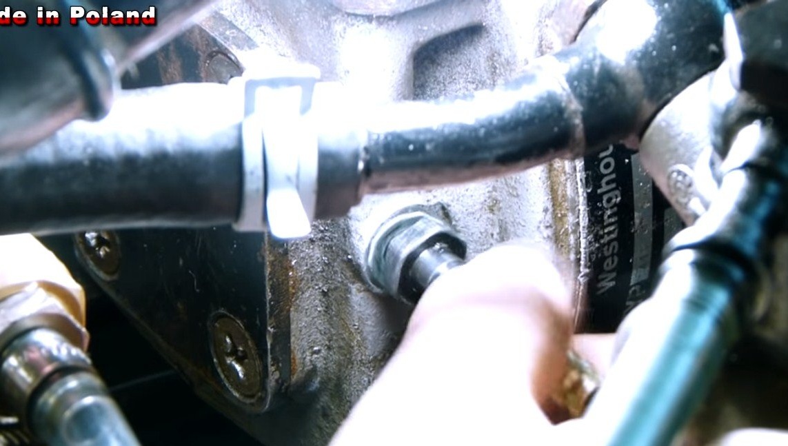
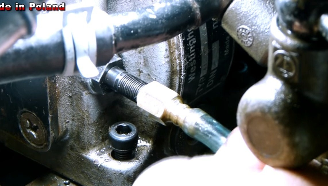
The compressor needs forced lubrication, for this we need a small pump. As a pump, the author decided to use an automobile pump from the power steering, we also need hoses, a manometer and other spare parts. A 3 bar valve is provided in the lubrication scheme, if the oil pressure becomes greater than this value, excess oil is sent back to the oil tank.
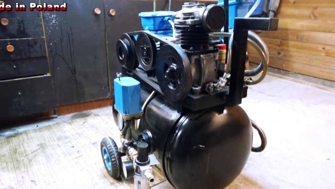
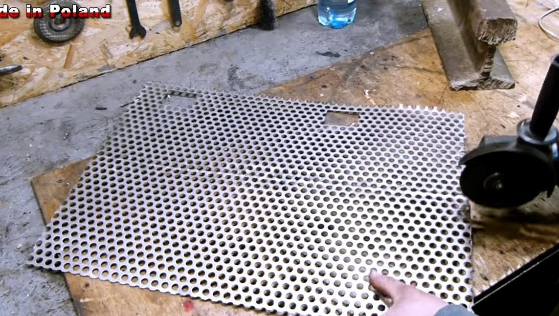
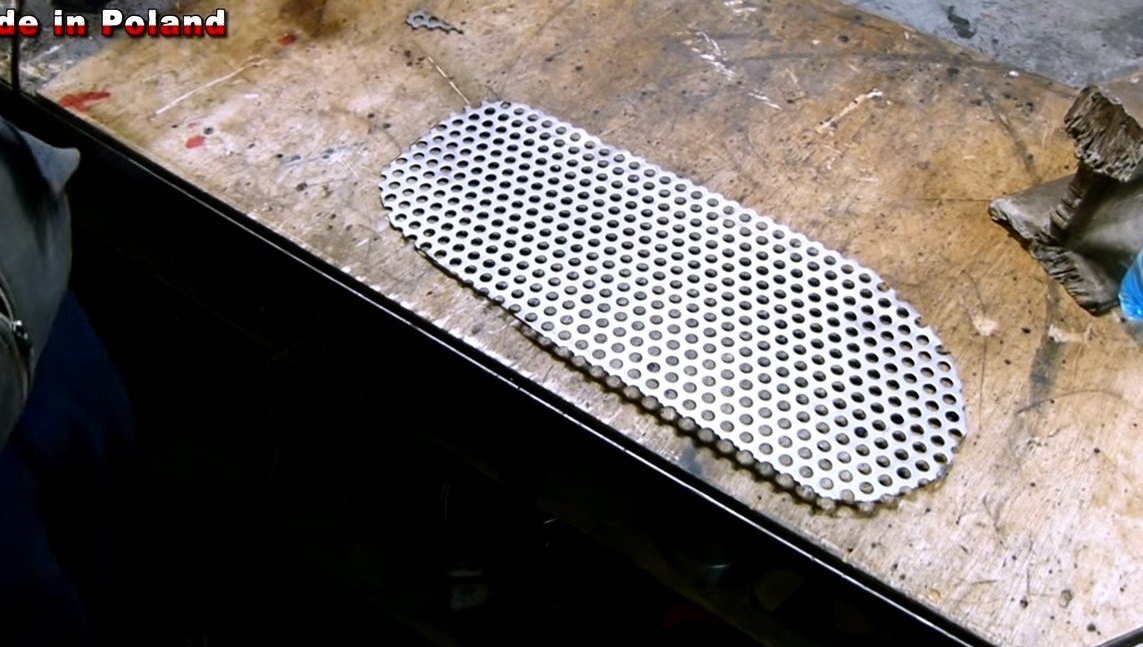
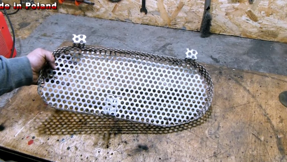
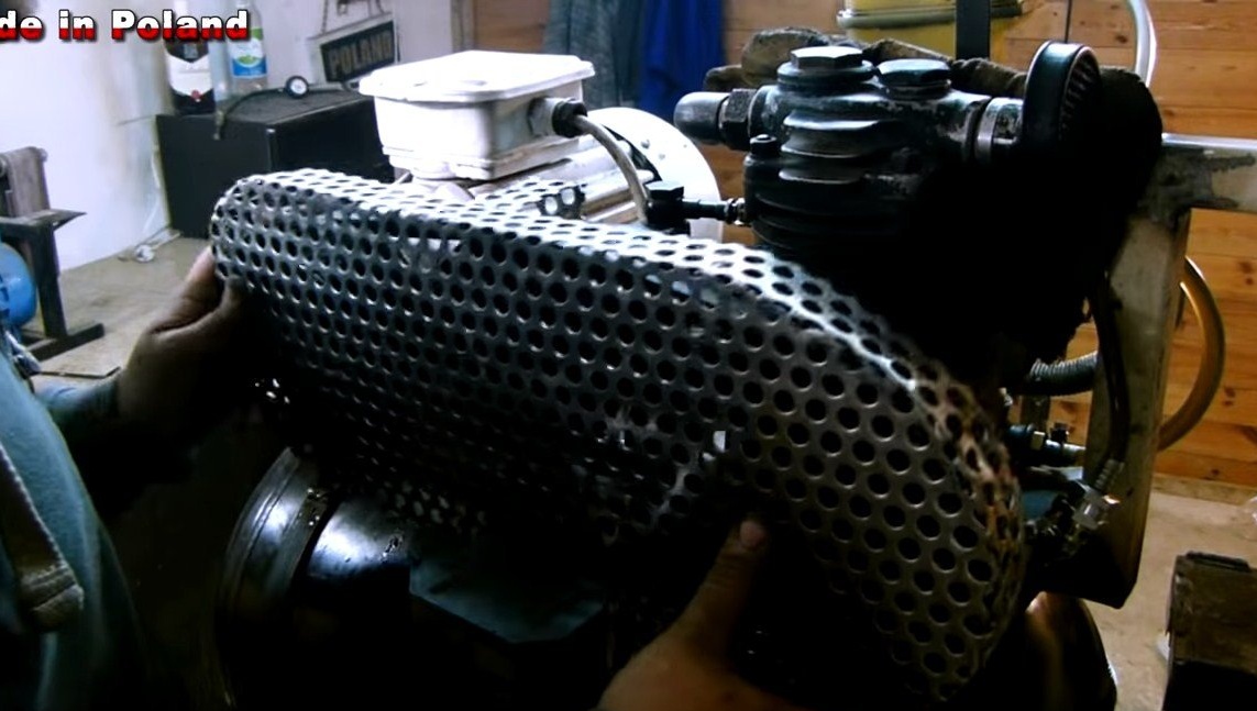
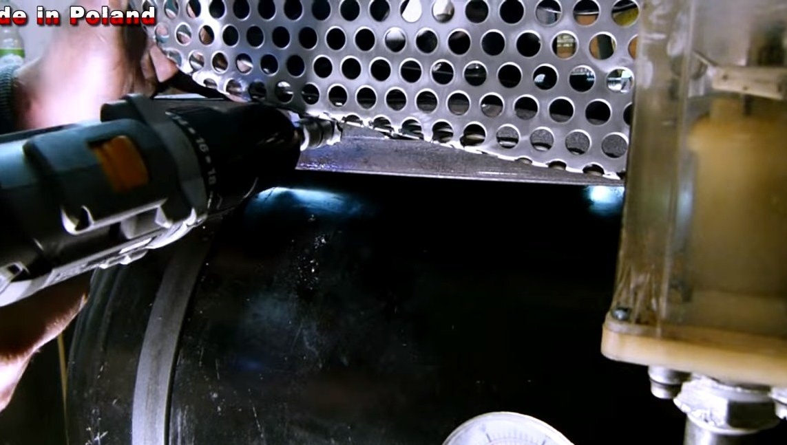
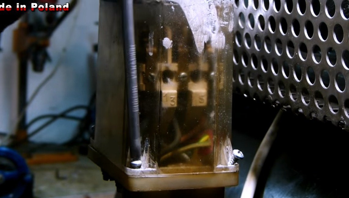
Step Eight. Protective shield
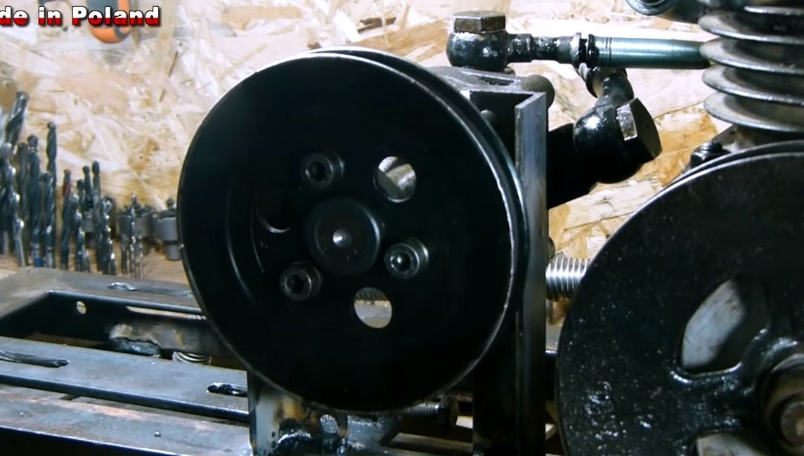
For a belt drive, you need to make a protective shield so that clothes or something else is not pulled there. For this we need a steel or aluminum grill. We cut it, rot and cook if necessary. Well, then we fasten the grill with screws to the car.
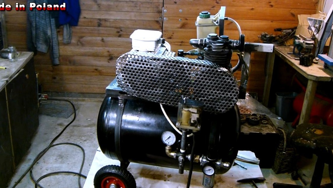
Step Nine. Painting and testing
Paint the compressor, now it looks like it’s purchased. We try to start home-made work, the pressure of 6 bar is reached in about two and a half minutes, while the tank capacity is as much as 60 liters.
That's all, the homemade product is ready. Everything turned out pretty interesting, I hope you liked the project. Good luck and creative inspiration if you decide to repeat it! Do not forget to share your ideas and homemade things with us!