

Recently, I became interested in the aircraft model theme. And then it started: he built a plane, bought equipment. Anticipating the quick demise of the first model without departing from the box office, he began to collect the second, while simultaneously working in the simulator. In general, I delayed my first real flight as I could, being afraid to break on the move model. And then, quite by accident, plowing the open spaces of aliexpress, I came across an interesting thing - a flight stabilization system. This is a small receiver-sized device that adjusts the flight of an aircraft, making it smoother, smoothing out pilot flaws. Started to search, read, they say and really a good thing for beginners. Well, here I fired up - I want and at least you crack. It’s just that the budget was already running out ... It would seem that the plane would build a question of 10 dollars in the ceiling, and buy equipment, buy a battery, buy a charger for it, an engine, a regulator, servos, propellers ... In short, a lot of things happen. A little depressed, but not giving up, I began to wither the back of my head: Duc, I can sort of solder. He began to search and almost immediately found a small article entitled "The aircraft stabilization system for 200 rubles." A very modest little article with a very modest implementation. But this is already something. He climbed to foreign forums - and lo and behold, this is a huge project with constant development! It is decided, we will do it!
The project is called MultiWii. Initially, it was conceived as a flight controller for multicopter based arduino, but over time, began to grow and improve. Now there is a code that allows you to put this stabilization system on aircraft and V wings. For the simplest execution, as in the above article, you will need only 2 things: arduino and accelerometer. All this can be soldered with wires, filled with hot snot and will work. But it can and will be, only I don’t work like that.
The project is called MultiWii. Initially, it was conceived as a flight controller for multicopter based arduino, but over time, began to grow and improve. Now there is a code that allows you to put this stabilization system on aircraft and V wings. For the simplest execution, as in the above article, you will need only 2 things: arduino and accelerometer. All this can be soldered with wires, filled with hot snot and will work. But it can and will be, only I don’t work like that.
And so, for the manufacture of a complete device you will need:
- Arduino PRO Mini, 5V, Atmega 328
- Three-axis accelerometer module with gyroscope MPU-6050
- Comb pls
- A piece of foil fiberglass, if you make the board yourself.
- SMD resistor 500-1500 Om
- LED 3 mm any.
From the tools:
- Soldering iron
- Solder
- Flux (I recommend F5)
- USB - UART Converter CP2102 or similar
- Model / clerical / mounting knife for making the case
Well, the little things, double-sided tape, scissors, ear sticks, tweezers, what should be in service with the youngest.
As I said, the project is growing and developing. So here you can screw another Bluetooth module to configure the controller from the phone, a barometer, to control the altitude, GPS to return the model "home" when the signal is lost. In addition to this, the topic of improvised receivers based on the same arduino and a cheap communication module A7105 is also growing, which without surgery interferes with my FlySky i6 equipment, so in theory you can connect these two projects and get full brains for an airplane, a glider or wings. And in a compartment with the aforementioned budget equipment, which is quietly flashed from 6 channels to 14, this generally comes out just perfect for a beginner for his money.
For this reason, I tried to make the circuit board for this device as simple as possible, that is, one-sided and with an iron. Of course, knowledge in radio electronics will be needed, at least the ability to solder more or less qualitatively, you can order a board and in extreme cases, but in essence it is a designer: I sewed an arduino, soldered it, the module and comb to the board, it’s ready. Minimum effort.
For this reason, I tried to make the circuit board for this device as simple as possible, that is, one-sided and with an iron. Of course, knowledge in radio electronics will be needed, at least the ability to solder more or less qualitatively, you can order a board and in extreme cases, but in essence it is a designer: I sewed an arduino, soldered it, the module and comb to the board, it’s ready. Minimum effort.
Arduino
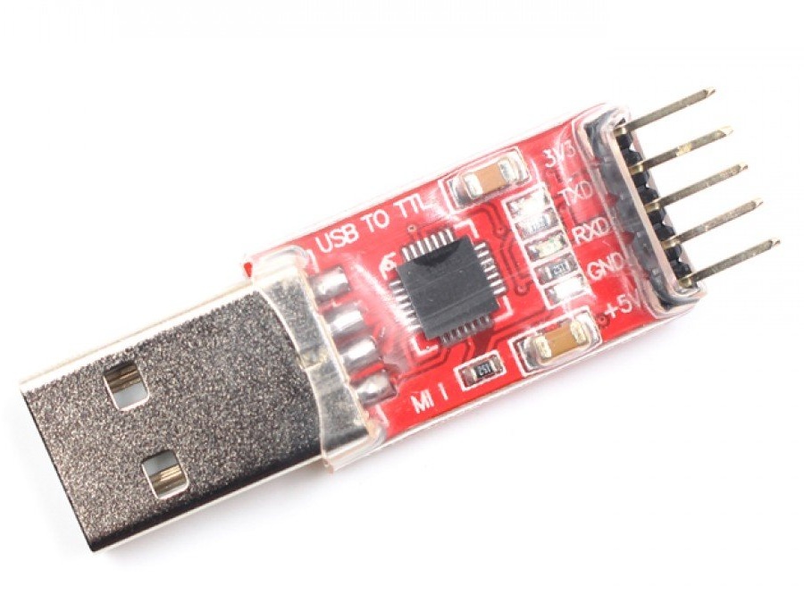
For arduinka firmware, you will need a special USB - UART (TTL) converter, because Arduino PRO Mini does not have a USB interface. You should not be afraid of this, as a rule, you can buy them in the same place where arduino and modules are sold. The only difference in the firmware through this converter is that you need to skillfully press the reset button on the arduino itself strictly at the time the sketch is downloaded, although there are converters that pull the reset foot themselves. I won’t describe the procedure for uploading a sketch; there are already a million articles and videos on this subject written and shot.
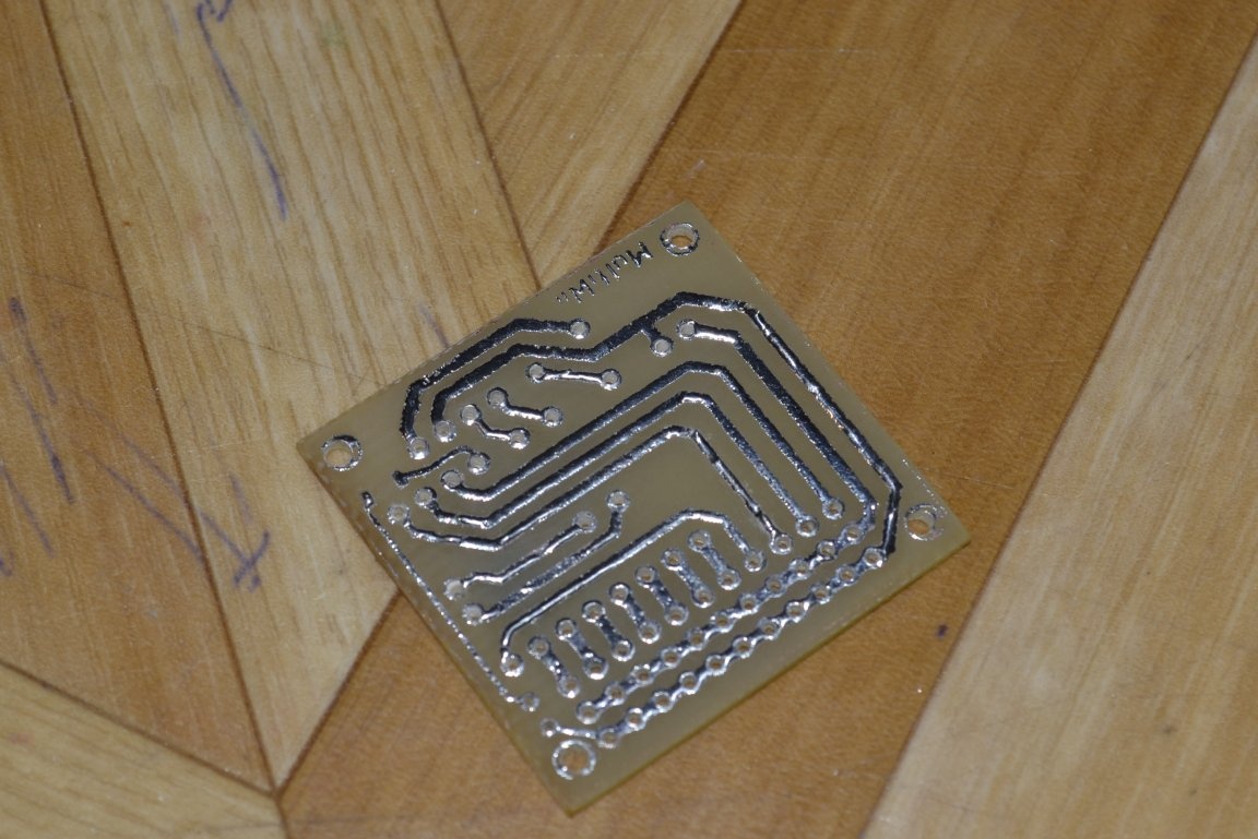
Pay
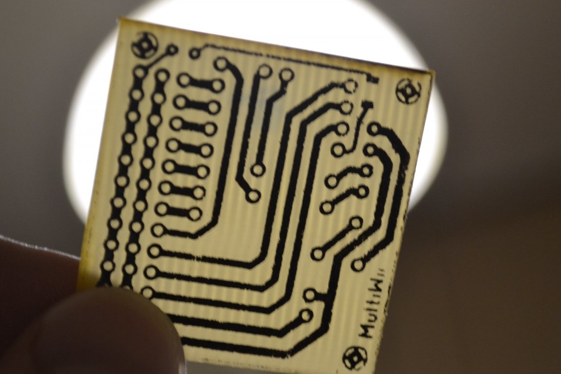
The next step is to make the board. The board is made by any available technology or ordered. I highly advise tearing up the tracks, it is better to use ROSE or WOODA alloy, so that the layer is as small as possible, large currents do not go around here, and it is better to protect copper from excessive corrosion, rain, snow, you never know, it's still not a home device. I made a rogue LUT, not the best result, you can do a lot of bad printer, but who cares)
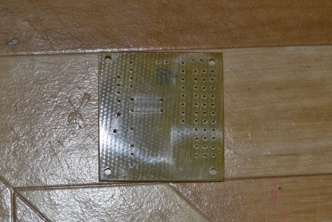
The first thing to solder the jumpers.
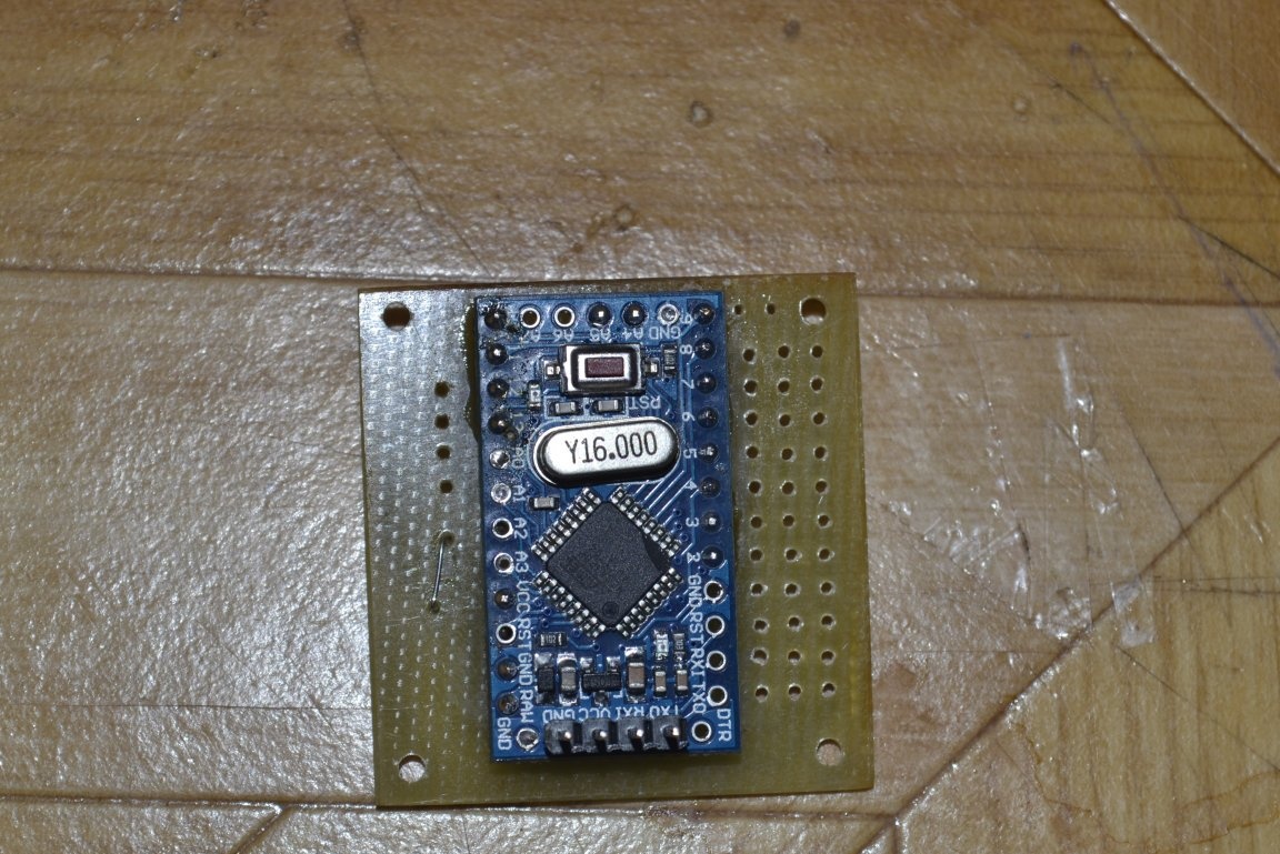
Behind them is arduino. The legs for flashing the arduinki need to be soldered up or angular sideways. You can fill in the sketch right away, you can not fill it in, it doesn’t matter, because the assembled device will still have to be connected to the computer, so the programming contacts should be easily accessible. The only advice is to check the arduino before soldering, fill in any test sketch and make sure that the board is flashing. Just solder then it will be hemorrhoids.
Well and everything else. The accelerometer is soldered on high legs and is located above the arduino. I will not hide a sin, I spied such a layout on a foreign forum at one sold, but I drew my own one-sided scarf. As for me, the absence of three jumpers is not worth the fuss with a double-sided board, no matter how bad form the presence of these same jumpers is not considered.
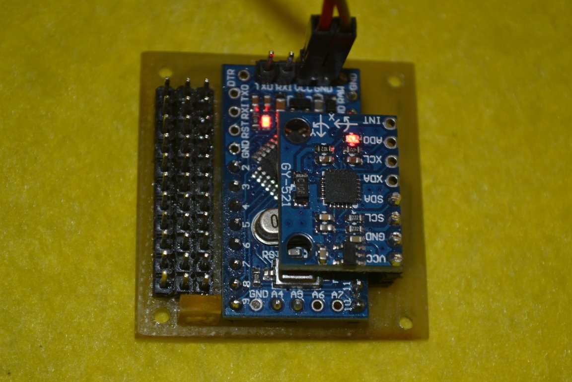
One caveat. There is one resistor and LED on the board. Resistor SMD format can be dropped out of some broken equipment, the nominal value of 500 Ohms - 1.5 kOhm. You can take an ordinary 3mm LED, I had a rectangular one, I soldered it.
At this stage, the device, in principle, can already be connected and configured, but as it seems to me incomplete. Electronics for radio-controlled models has long acquired a modular character. Therefore, I think this device should be brought to the finished module, which is easy to mount in the model and connect. To do this, he needs a case. A good option would be to print it on a 3D printer, the plastic used for printing is lightweight and durable. But not everyone has it. You can make the case by thermoforming, on the Internet there is a ton of information on how to make a simple machine for this from a vacuum cleaner, timber, and a piece of plywood. But for this you need to make a blockhead, and this is laziness. On this, I took the path of least resistance. Yes, and such a method will be similar to this article - to make it as simple as possible using a minimum of tools.
Housing
I cut two pieces of plastic according to the size of the board, in my case thin transparent PVC, but you can use anything you like, a box from a disk, for example. I didn’t take intermediate photos, but I think it will be clear anyway.Using a ruler, I measured the distance to the contacts on the board, and cut windows for them on the top of the "case". I drilled holes coaxially with the holes on the board and connected them together with improvised rivets from the tubes from the ear sticks. To make such a rivet, it is enough to carefully hold the tip of the tube in the flame of the lighter and when an influx forms, press it against the body of this lighter. On the reverse side, we cut the tubes leaving a couple of millimeters and do the same. As spacers used segments of the tube from the dropper. As a result, such a sandwich came out:
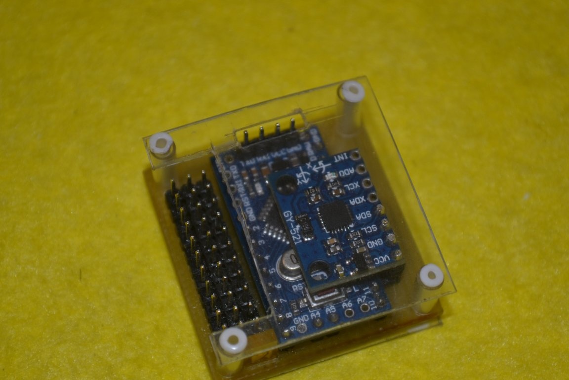
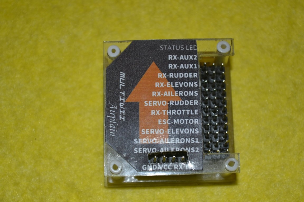
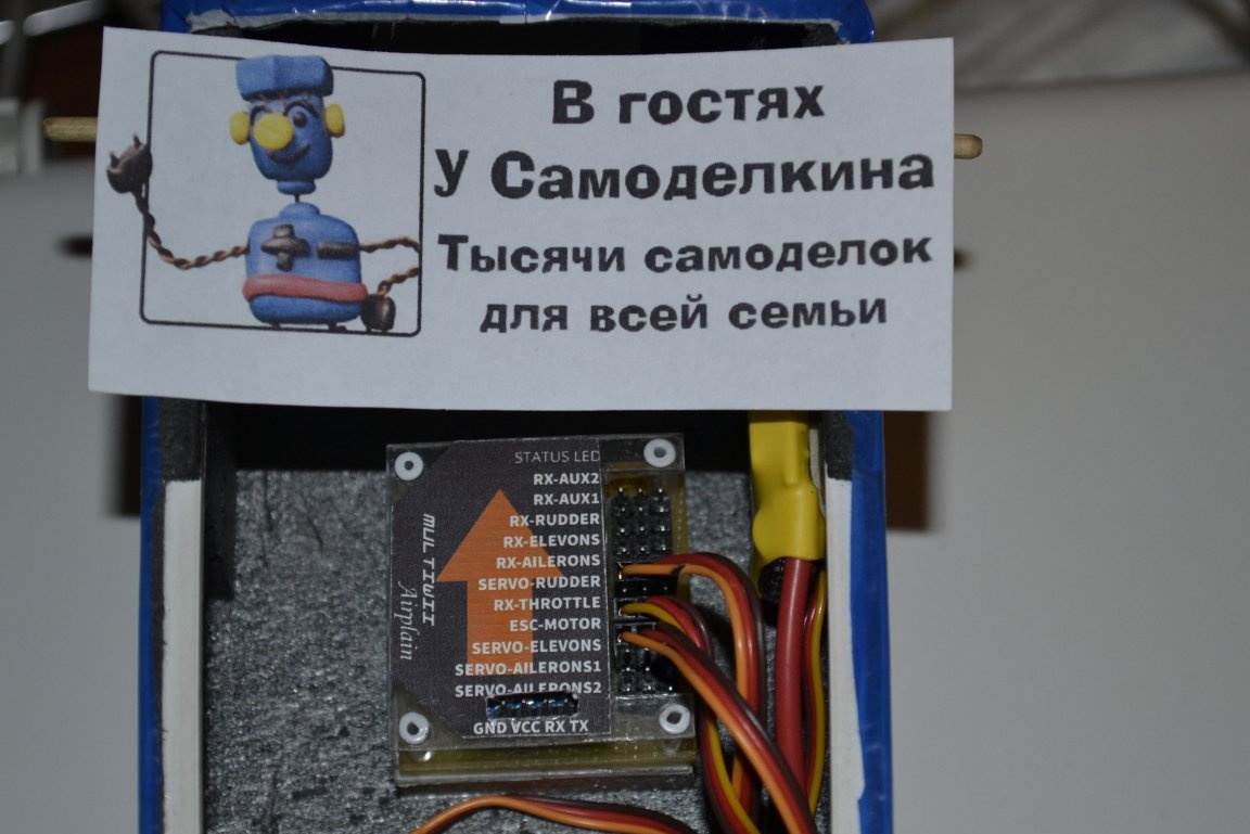
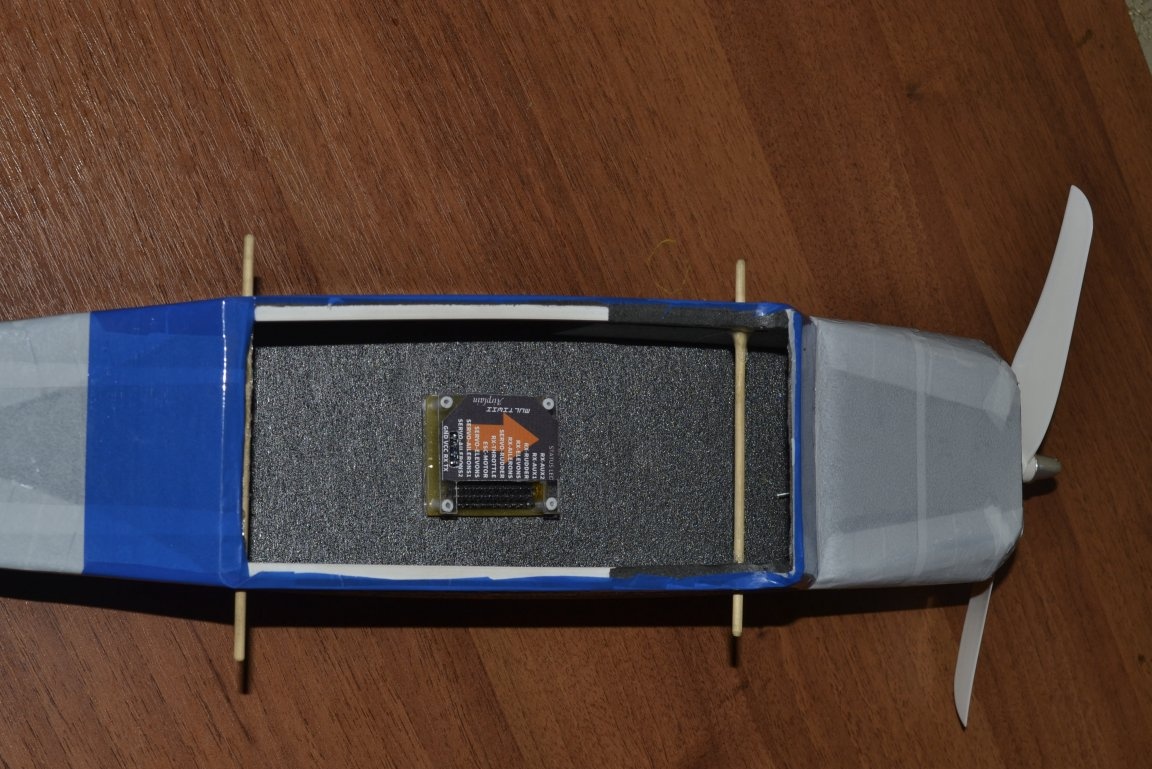
Easy to do, lightweight, simple and reliable. It is already convenient to mount it in the fuselage of the aircraft by gluing to the bottom a pair of strips of "automobile" double-sided tape. But for the full picture, you still need a nameplate, which will tell you in half a year, when already eleven other schemes will be assembled, what to connect to.
The nameplate printed on self-adhesive glossy paper. Recently bought specifically for such purposes. Previously, I did this: printed on what is, laminated with adhesive tape and glued to double-sided tape. The most attentive could evaluate my level of English)
Now the device can really be called a ready-made module. The total weight of 15.5 grams. Too much when compared with the purchased, but in general, very much nothing. At least my model with a range of 950mm will pull without problems. But if you chase the weight, you can unsolder the arduino from the loose powder directly on the board, save 2 grams, use a thin millimeter textolite (I used which one, one and a half or two millimeters, did not measure), do not make the case. But is it worth those 5 grams? For example, the weight of the native receiver from my app is 16 grams.
The device should be located in a horizontal plane, the arrow indicates the direction of movement. Also, the device can not be installed upside down. For clarity, I am attaching a picture.
Setup, calibration
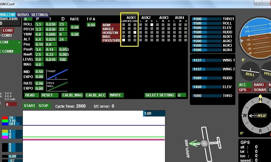
Now go to the settings. First you need to connect the device to the computer, and then open the attached graphical user interface. If there are no problems with the drivers, then the port should appear in the program:
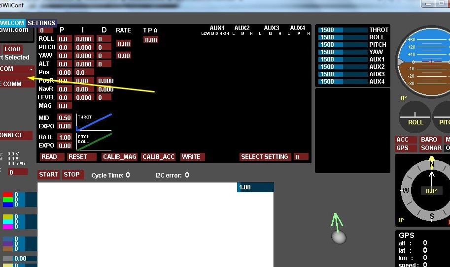
We select it. Now you need to calibrate the accelerometer. We press the READ button and if everything is correct, we can observe the readings from the sensor in real time. We lay the device on a flat surface and press CALIB_ACC. Usually a “flat surface” is a table near the computer, so when you press the calibration, keep your hands away from the table. Who does not remember, the accelerometer is an acceleration sensor. So any vibrations or vibrations in the calibration will not have a positive effect. But if possible, it is better to calibrate it on a surface exposed to the level. The gyroscope is calibrated itself each time it is turned on, so it does not need to be calibrated. The only thing is that when you turn on the model should be stationary. That is, we put the model on the ground, turn it on and do not touch it. The gyroscope is calibrated immediately. Calibration is indicated by a LED signed as STATUS.
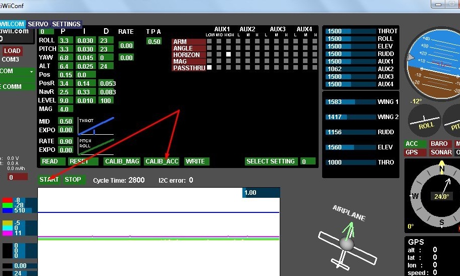
Immediately configure AUX1. It is convenient for him to use a three-position switch, if there is one on the transmitter. At a low level (the switch is in the first position), stabilization is disabled, at an average level (and position, respectively) an accelerometer is turned on, and at a high level, a gyroscope and an accelerometer. For a normal flight, in principle, an accelerometer is enough, a gyroscope is usually used for FPV flights. What would be as I described - set the values as shown here:
A bit about other settings. PID - these are the settings of the stabilization itself. In a nutshell:
- R is the value of the corrective force applied in order to return the model to its initial position.
- I Is the period of time during which angular deviations are recorded and averaged.
- D - this is the speed with which the model will return to its initial position.
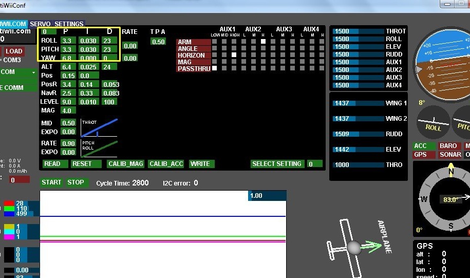
I advise you not to touch these settings before the first flight. Stabilization works well at basic values, well, and there you can already tighten up if something does not suit you.
Further. TPA responsible for the value of these PID settings depending on the gas position. At a value of 0.00, the PID values will be the same at any gas position, that is, as expected, at any speed. With a value of 1.00 with a gas, 100% PID will be zero, that is, stabilization will be disabled. At a value of 0.5 per 100% of the gas, the pids will be equal to 50%, respectively. Here it’s already being tuned for the plane and for your aerobatic style, so far I have left 50%.
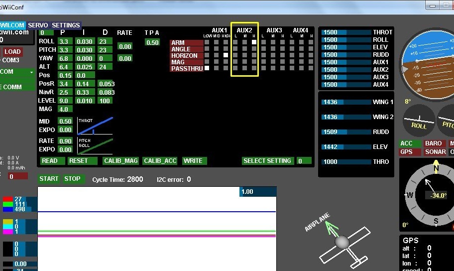
Also on the channel Aux2 you need to configure the reinforcement. Arming is a copter term. Humanly, this is called unlocking the engine. On airplanes, this is usually implemented through control equipment, but since This controller was originally copter - here it was done quite tough. In general, we hang some kind of free toggle switch on AUX2, in the program we set ARM to a high level. Here, someone may want to cheat and set the unlock at all levels of AUX2, but just do not fail. In this case, the multiviy refuses to start the engine at all. It can be assumed that this is a bug, but I think that protection is soon. The plane still only flies forward, and only Gods knows where the uncontrolled copter will explode.
By the way, this is actually convenient. Specifically, in my app, the engine is unlocked by moving the toggle switch up. In this case, the equipment must be turned on just with all the toggle switches in the upper position. That is, it turns out that you need to turn on the equipment, move the toggle switch down to block the engine, and then transfer it back up to unlock. And you can’t invert the main thing. Immediately it turns out humanly, in the upper position the engine is locked, in the lower unlocked.
Further. TPA responsible for the value of these PID settings depending on the gas position. At a value of 0.00, the PID values will be the same at any gas position, that is, as expected, at any speed. With a value of 1.00 with a gas, 100% PID will be zero, that is, stabilization will be disabled. At a value of 0.5 per 100% of the gas, the pids will be equal to 50%, respectively. Here it’s already being tuned for the plane and for your aerobatic style, so far I have left 50%.
Also on the channel Aux2 you need to configure the reinforcement. Arming is a copter term. Humanly, this is called unlocking the engine. On airplanes, this is usually implemented through control equipment, but since This controller was originally copter - here it was done quite tough. In general, we hang some kind of free toggle switch on AUX2, in the program we set ARM to a high level. Here, someone may want to cheat and set the unlock at all levels of AUX2, but just do not fail. In this case, the multiviy refuses to start the engine at all. It can be assumed that this is a bug, but I think that protection is soon. The plane still only flies forward, and only Gods knows where the uncontrolled copter will explode.
By the way, this is actually convenient. Specifically, in my app, the engine is unlocked by moving the toggle switch up. In this case, the equipment must be turned on just with all the toggle switches in the upper position. That is, it turns out that you need to turn on the equipment, move the toggle switch down to block the engine, and then transfer it back up to unlock. And you can’t invert the main thing. Immediately it turns out humanly, in the upper position the engine is locked, in the lower unlocked.
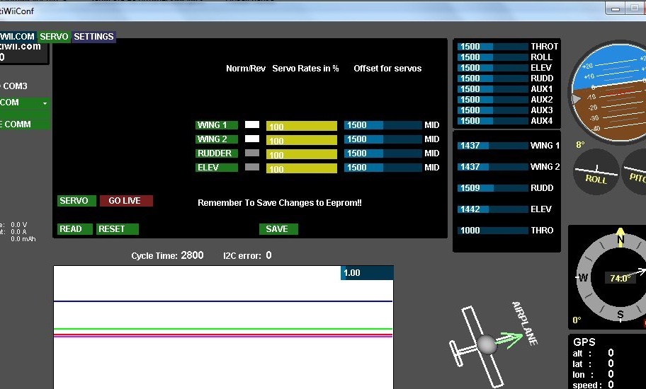
In the tab SERVO you can reverse the servos if necessary. Here they did it somehow intricately. First you need to press SERVO. A list of servos and levels will appear. If you press the reverse button now and try to save, nothing will be saved. First you need to press GO LIVE, after which when the sticks are rejected, it will be possible to observe the level deviation in the window. Now we press the reverse button of the desired channel and after that we press SAVE. Now everything has been recorded.
An important point about disconnecting the device from the computer. If you pull out the programming wires from the device or pull out the converter from the USB port without closing the COM port or the MultiWiiConf program, the system will crash and the blue screen will be approximately 100% likely. At least on my laptop it is. I even specifically checked. I don’t know if this is a problem with my hardware or if it reacts it is visible to the virtual COM port, but if it is warned, it means it is armed. Keep in mind.
And a few more settings that may come in handy. If your receiver knows how to issue a PPM signal, you might want to transmit it to the multiview. To do this, open the firmware file, go to the config.h tab and look for the section PPM Sum Reciver (glorified Ctrl + F). Here you need to uncommentize 2 lines. Who is not in the subject, uncommenting - this means removing two slashes at the beginning of the line. It was like this:
And a few more settings that may come in handy. If your receiver knows how to issue a PPM signal, you might want to transmit it to the multiview. To do this, open the firmware file, go to the config.h tab and look for the section PPM Sum Reciver (glorified Ctrl + F). Here you need to uncommentize 2 lines. Who is not in the subject, uncommenting - this means removing two slashes at the beginning of the line. It was like this:
// # define PPM_ON_THROTTLEIt became so:
#define PPM_ON_THROTTLEYou also need to uncomment one of these lines, depending on the hardware:
// # define SERIAL_SUM_PPM PITCH, YAW, THROTTLE, ROLL, AUX1, AUX2, AUX3, AUX4,8,9,10,11 // For Graupner / Spektrum
// # define SERIAL_SUM_PPM ROLL, PITCH, THROTTLE, YAW, AUX1, AUX2, AUX3, AUX4,8,9,10,11 // For Robe / Hitec / Futaba
// # define SERIAL_SUM_PPM ROLL, PITCH, YAW, THROTTLE, AUX1, AUX2, AUX3, AUX4,8,9,10,11 // For Multiplex
// # define SERIAL_SUM_PPM PITCH, ROLL, THROTTLE, YAW, AUX1, AUX2, AUX3, AUX4,8,9,10,11 // For some Hitec / Sanwa / Others
In my case, this is the second line, where is Futaba (what do I have FlySky equipment for). Here it may be necessary to select empirically, it is possible to prescribe the desired sequence yourself. One way or another, there’s nothing complicated about it. We compile the sketch and fill it with a new one. To return to normal mode, do the opposite, comment on lines, compile, fill. I want to pay attention, after reloading the sketch all the settings and calibration will be knocked down, keep this in mind.
Another common problem that, as I understand it, is often encountered, and I am no exception.After everyone has assembled and configured, connected all the steering wheels - the rudder floats away. The handles on the remote control were jerked - it seemed to be in place, but if the glider shook a little - it floats away to the side again, and at a rather serious angle. It is treated elementarily: in the GUI program, set the value YAW - I to zero. The problem goes away right away.
Another common problem that, as I understand it, is often encountered, and I am no exception.After everyone has assembled and configured, connected all the steering wheels - the rudder floats away. The handles on the remote control were jerked - it seemed to be in place, but if the glider shook a little - it floats away to the side again, and at a rather serious angle. It is treated elementarily: in the GUI program, set the value YAW - I to zero. The problem goes away right away.
Well, the video works:
Conclusion
In general, if you have experience in the manufacture of printed circuit boards, the device is assembled in one evening. I already made the basic settings for the plane myself in the sketch myself, the rest I described in the article. Information had to be collected in various forums, mainly foreign ones. Nevertheless, I give links to various sources that will help in case of other problems, although they should not be.
, from which I borrowed the form factor of the board. I do not offer to buy, but the topic has a detailed guide on the firmware configuration in English. True for the old firmware version, but in the new one everything is almost the same. There is also a mode in the branch that allows you to adjust PID settings in real time through the potentiometer control equipment.
. He has his own personal rewritten firmware, they say that it is ideally optimized for airplanes. But again, the old version. You can try it, but for the appearance of glitches not described in this article, I am not responsible. There are many descriptions of settings.
. But the basic useful information that is described there, namely the treatment of the rudder, I have already outlined. Nevertheless, you never know.
The total cost ranges from 4-8 dollars, depending on what price the arduino and the module were bought, is there a textolite at home, is there a programmer. In any case, this is several times less than the market value from $ 20 per device with the same characteristics. Personally, it cost me $ 2, a stock of arduino for such purposes was purchased a year ago, there was not only a module.
In the archive attached below is a sketch for arduino, MultiWiiConf setup program for different operating systems, a circuit board file (to open you need SprintLayout no less than version 6), as well as a printed circuit board in PDF format, for those who do not have a laser printer at home ( need to print at 100%).
Good luck to everyone in your work!