
In this article, the author will talk about how he repaired and calibrated his torque wrenchthat has stopped working.
One day, the author discovered that his torque wrench no longer “clicks”. The ratchet broke. He cut the bolt. Since the key was quite cheap in the auto parts store, there was no point in sending it for “warranty service”. Therefore, the master decided to disassemble it in order to look at the internal device and find out how it works, and try to repair it.
The repair was even easier than he expected, and now his key is again fully functional.
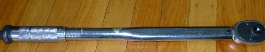
Step 1: Wrench
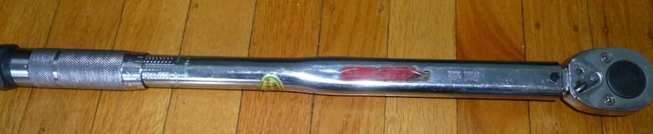
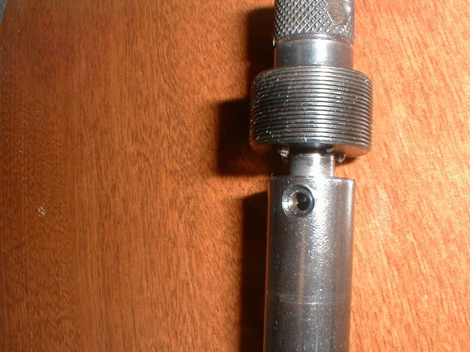
As you can see, this is a torque wrench. Just turn the knob to set the required force, which is engraved on the handle. In order not to accidentally knock down the adjustment while you are tightening something, there is a handle at the end that is screwed to fix the adjustment.
With the switch, the ratchet is returned like a normal ratchet wrench, but the click only acts in the direction of tightening.
This key should work as follows: set the desired force by turning the handle until the engraving on the handle meets your requirements. Turn the knob at the end to lock this adjustment. Then place the head on the nut and tighten the bolt / nut until the wrench clicks.
Since this is a “precision” measuring device, it should only be used to measure force and tighten to the required moment of force. That is, you must first tighten the nut / bolt manually, using another tool with a ratchet mechanism or a wrench.
The principle of its operation is quite simple: the head with a ratchet mechanism is connected to a lever held in place by a bearing resting on a recess on this lever under spring pressure. The higher this pressure, the higher the force required to overcome the resistance emanating from the bearing exiting the recess. Once this effort is achieved, the lever “breaks out” by “clicking” on the other side of the main body of the wrench.
Step 2: Disassembly
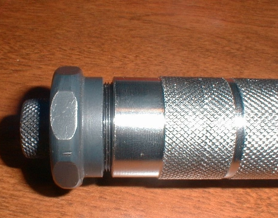
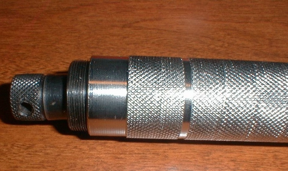
To disassemble, loosen the locking knob and unscrew the adjustment part of the handle until the spring loosens.
Then remove the calibration lock nut located on the end of the handle. This is a large nut that is screwed into the calibration sleeve, which, in turn, is screwed into the handle.
Step 3: Disassembly Part 2
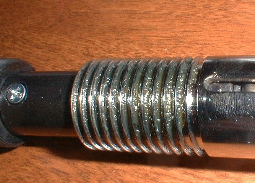
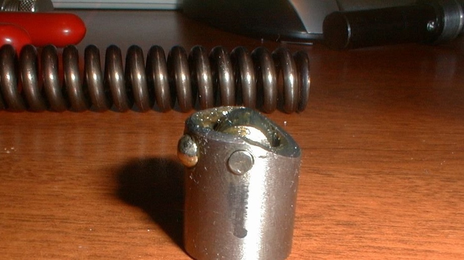
Remove the calibration sleeve from the handle. The sleeve is a thin-threaded metal cylinder with one closed end that connects to a piston that exerts pressure on the spring.
By screwing more / less of it into the handle, the key can be calibrated. This works by adjusting the spring tension without adjusting the handle itself. This part also has pin holes that work with the lock handle assembly.
To remove the calibration sleeve from the handle, unscrew it by slowly turning the handle to a higher key force.
Turning the handle should allow you to unscrew the sleeve, the blocking unit can prevent this, so we turn the handle. Do not remove this part if there is NO pressure on the spring; otherwise the spring will fall out and all that it presses on.
Step 4: Disassembly Part 3
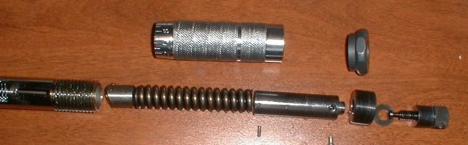
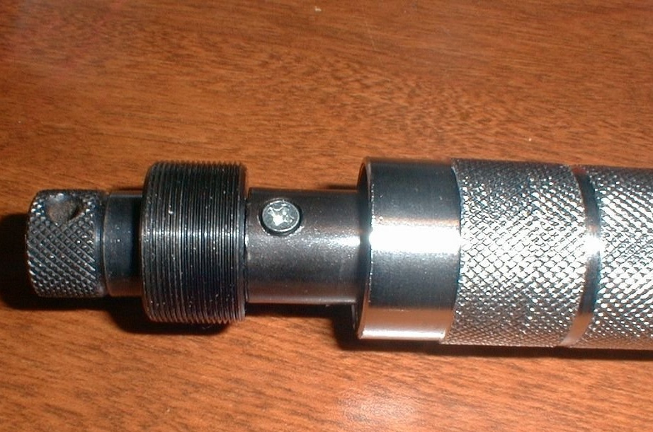
Now remove the lock handle and the entire adjustment assembly from the wrench body. As you can see in the figure, the lock handle, calibration sleeve and piston are designed to move up and down along the slot in the wrench body. There is a pin that holds the piston in place, keeping it from twisting and stretching. The handle itself holds the pin in place during normal operation.
To disassemble this, you must remove the handle. There is a screw in the piston that holds the lock handle from completely unscrewing. It also prevents the pins in the calibration sleeve from falling out.
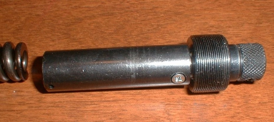
Once this fixing screw has been removed, the lock handle can be completely unscrewed from the piston. Then the handle, calibration sleeve and piston can be separated from each other.
After removing the calibration sleeve, the handle can be completely unscrewed. After the handle is removed, the pin holding the piston in place is easily removed. The remaining internal parts are then easily removed from the wrench body.
Step 5: Lock handle and ratchet gear

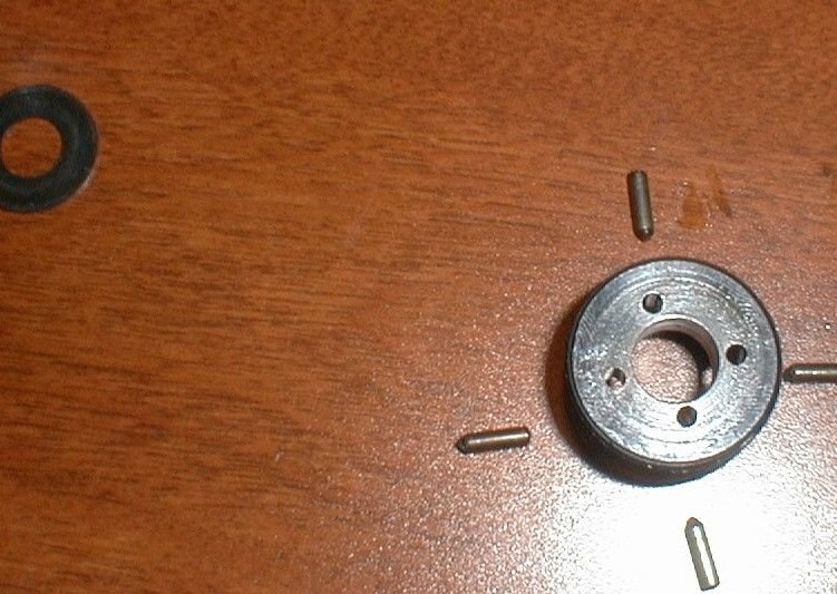

As the lock handle is tightened, this increases pressure on the washer. This washer pushes 4 pins through holes in the calibration sleeve to interact with slots inserted into the piston. After tightening, the pins are recessed into the grooves, fixing the calibration sleeve in place, and if the calibration lock nut is in place, the handle is also locked in place.
This is useful when calibrating a wrench, since you need to lock the lock knob to put the locknut back in place without turning the nut of the calibration sleeve (and thus losing the calibration just installed).
Looking at the other parts that have been released, you can see how the adjusting handle just pulls a large spring more and more. This spring pushes the roller bearing part down as well as the serrated end of the lever that extends from the ratchet head.
This lever is attached to the main body with a single pin, from the bottom near the head, creating a lever. The force you apply to the handle is transmitted through the spring and bearing to the lever. The greater the spring tension is achieved by adjusting the handle, the higher the force on the bearing assembly, the greater the force necessary for the bearing to break out of the recess and for the lever to “click” on the other side of the housing.
When the force is released, the spring pressure returns the bearing into place, causing another “click”.
Step 6: Build
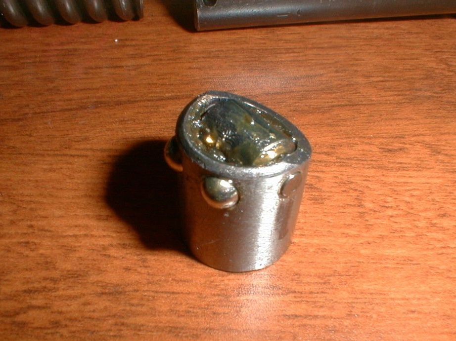
Everything is going in reverse order. However, the main thing is to make sure that the bearing is installed in the correct orientation.
The problem with which the author disassembled his wrench was that the spring tension was loosened to such an extent that the bearing could slide freely inside the wrench and actually rotated, so he no longer sat in the groove, but instead simply lay.
Therefore, the wrench stopped clicking. Before assembling the bearing, make sure you clean it and lubricate it again.Insert it so that the main roller bearing is aligned with the groove, and the side with ball bearings is opposite the inclined surface of the main lever. The inclination of the bearing assembly must match the inclination of the lever.
Then add the spring, piston, calibration sleeve, locking pins, washers, handle and locking screw, piston locking pin and handle. Do not touch the main locknut until we calibrate the key.
Step 7: Calibration
A torque wrench measures how much force is applied perpendicular to the lever at a known distance from the lever pivot point. In case of tightening the bolt / nut, this force is the pivot point. Measurements are usually in N * M or Ft-Lbs (sometimes Kg-M) or in Lb for lower forces. To calibrate the torque wrench, you must set the known “torque” and adjust the wrench. He must click when the moment of force exceeds a known calibration point. Since the moment of force is equal to Newton * meter, we simply calculate and adjust the lever and weight a little.
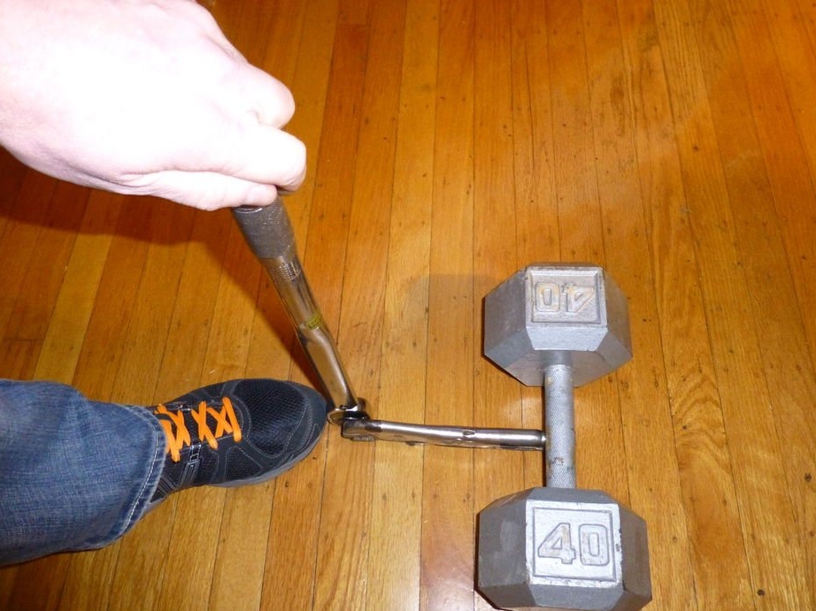
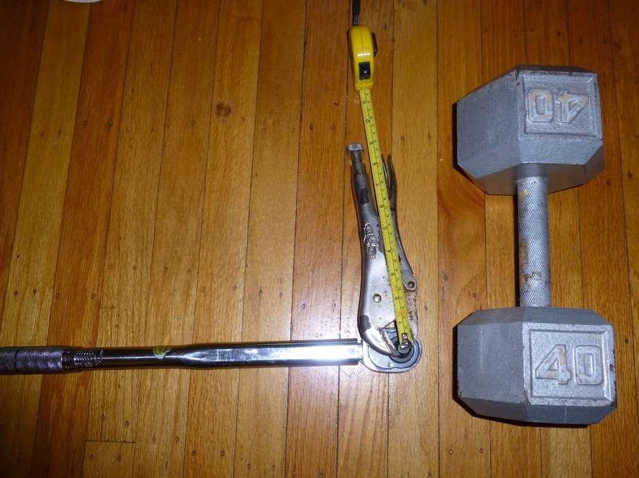
The author used a wrench and pliers with a lock, as well as 40 pounds (18 kg.) Dumbbells, to calibrate it. Pliers with a lock are fixed on the socket head and have a handle long enough to create a known moment of force with a dumbbell. The dumbbell rests on the handle of the pliers with a latch at a known distance from the center of the ratchet head (21 cm). This creates a moment of force of 18 * 0.21 = 3.78 kg / m = 37.07 N * m.
The entire assembly rests on a rounded ratchet head, and you can try to lift the weight using a wrench. When the calibration is correct, the key will click right about 37.07 N * m when the weight just rises. Please note that this will not be entirely accurate, and if a specific and accurate moment of force is required, a real calibration setup should be used. And this method is the fastest and easiest way to get the exact key in the "field conditions".
To do this, tighten the calibration sleeve to the middle of the handle. Set the handle to 37.07 N * m and check the torque. If the key clicks before the load moves, pull the handle away from the spring and retighten the calibration sleeve. If the weight can be lifted without clicking, loosen the calibration sleeve. Repeat this lifting and adjusting process until you can barely lift the weight. Once this parameter is found, tighten the lock knob, then reinstall the main locknut and tighten it to lock the calibration sleeve in place. Your key should now return to normal.
Other calibration setups use a long rod attached to the socket that matches the wrench. The bar is horizontal and can be rotated on the ratchet head. Then the weight is suspended at the end of the rod with a rope, and a process similar to that described above is performed to set up the calibration. More professional and accurate torque wrenches are simply hung out under their own weight, and the dial displays the moment of force when light pressure is applied to the wrench.
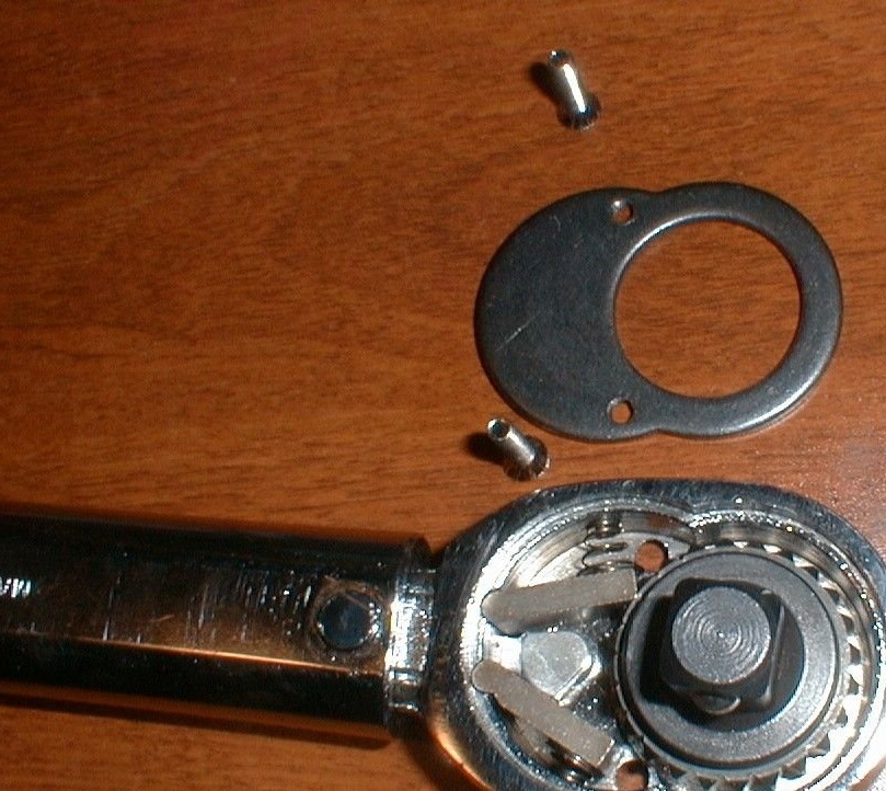
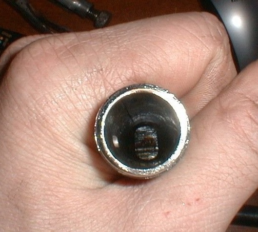
Step 8: Ratchet Head
This part has little to do with the torque moment of the torque wrench. The wrench can be retuned from measuring the moment of force when tightening, to measuring when loosening (or measure the force for bolts and nuts with left-hand thread).
The ratchet head is held together by two screws securing the plate to the main body. After the screws are removed, the plate easily comes off, exposing the inside of the ratchet head. The ratchet works with two rotary spring-loaded metal rods interacting with the slots on the head itself.
A cam attached to the guide lever pushes one bar to control the direction of rotation of the ratchet.Since the torque wrench only latches in one direction, only one direction can measure the moment of force.
Another direction is the use of a torque wrench as a regular wrench (not recommended, as this may remove it from the calibration).
To change the direction of the torque arm, simply remove the head and turn it over so that the head points to the other side of the wrench. This can be done since the holes in the plate and head are identical.