
Today we look at 3 simple charger circuits that can be used to charge a wide variety of batteries.
The first 2 circuits operate in linear mode, and linear mode primarily means strong heating. But the charger is a stationary thing, not portable, so that efficiency is a decisive factor, so the only minus of the presented circuits is that they need a large cooling radiator, but otherwise everything is fine. Such schemes have always been and will be used, since they have undeniable advantages: simplicity, low cost, they do not "spoil" the network (as in the case of pulsed circuits) and high repeatability.
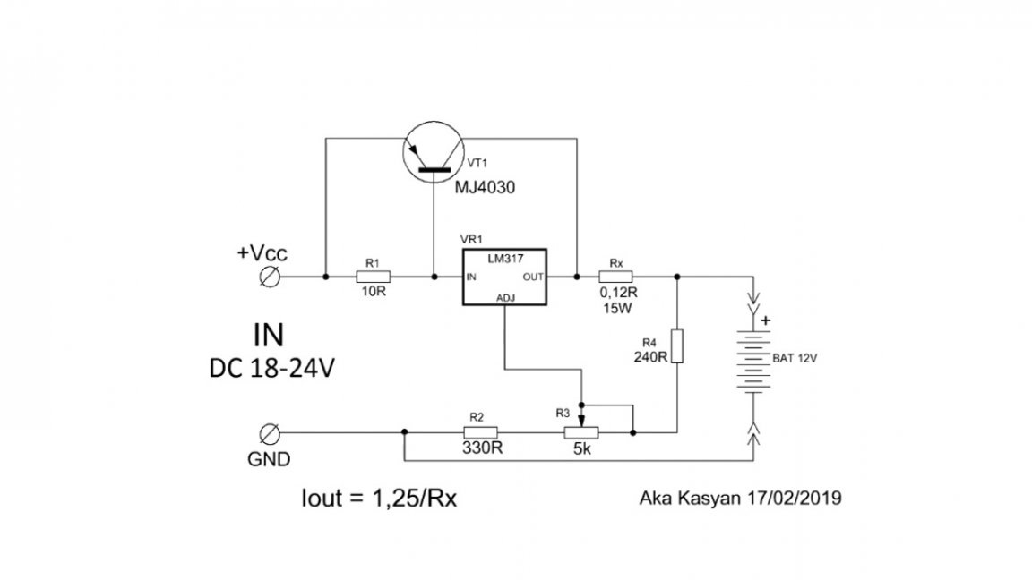
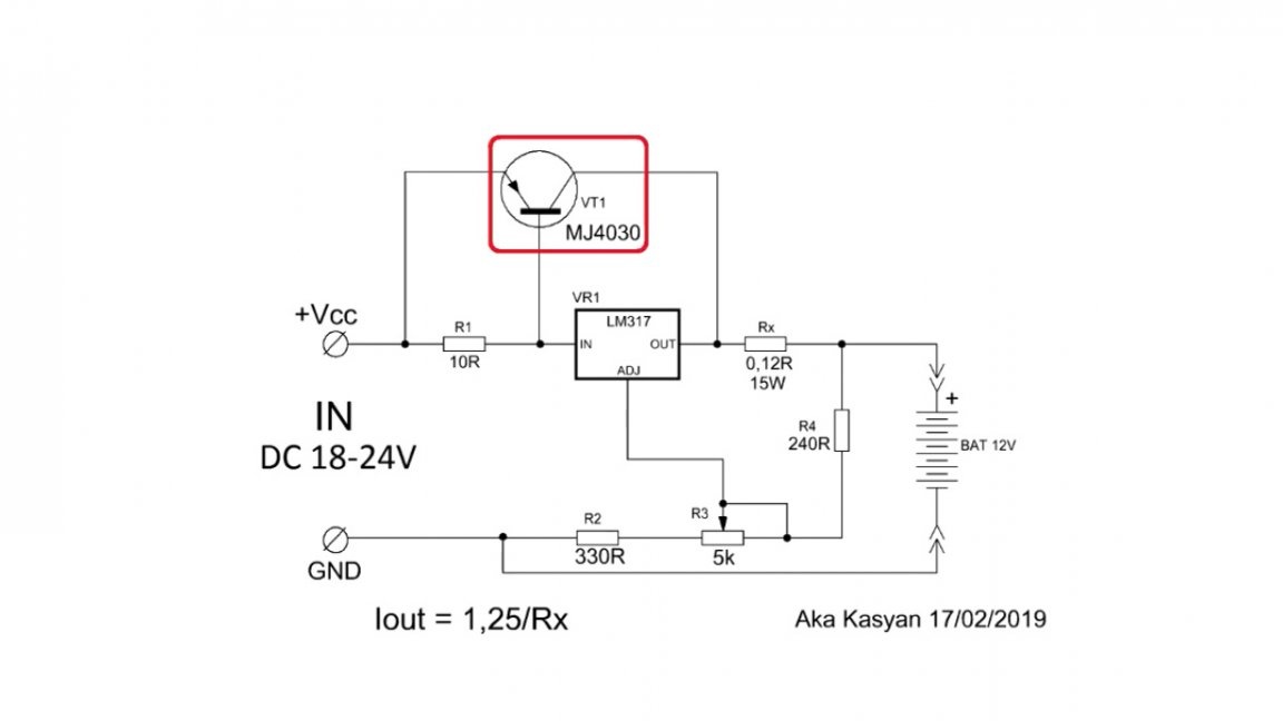
Consider the first scheme:
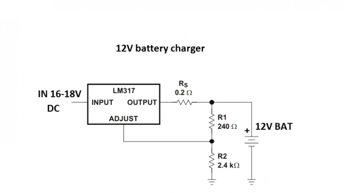
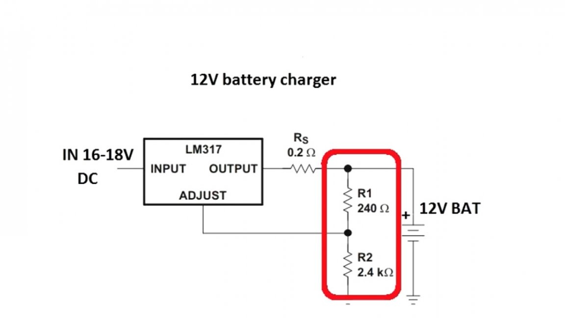
This circuit consists of only a pair of resistors (with which the voltage of the end of charge or the output voltage of the circuit as a whole is set) and a current sensor that sets the maximum output current of the circuit.
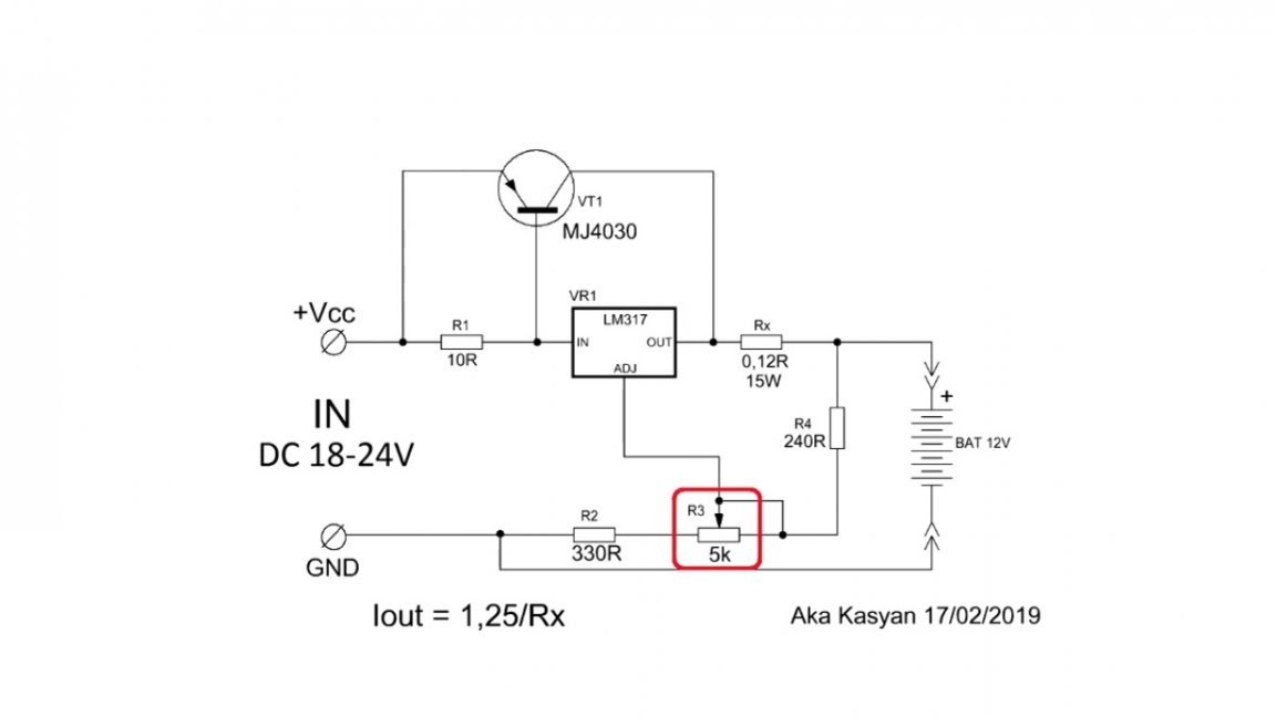
If you need a universal charger, the circuit will look like this:
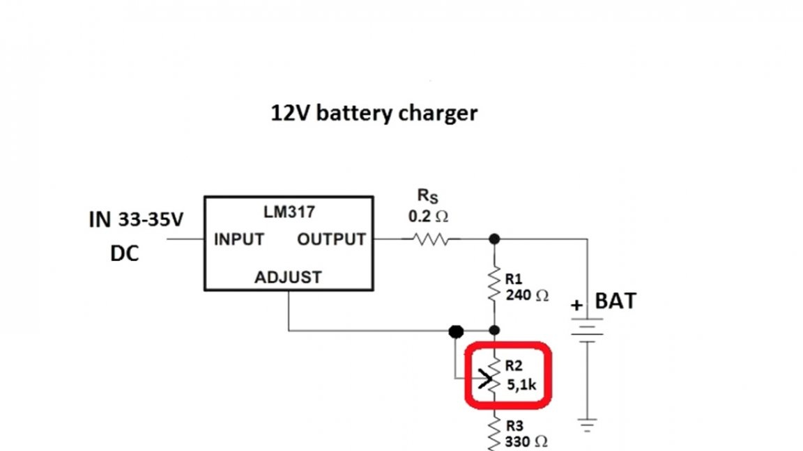
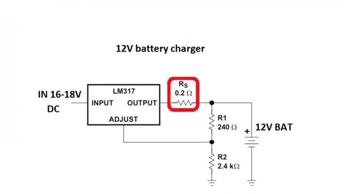
By rotating the tuning resistor, you can set any output voltage from 3 to 30 V. In theory, up to 37 V can also be used, but in this case, you need to supply 40 V to the input, which the author (AKA KASYAN) does not recommend. The maximum output current depends on the resistance of the current sensor and cannot be higher than 1.5A. The output current of the circuit can be calculated by the specified formula:
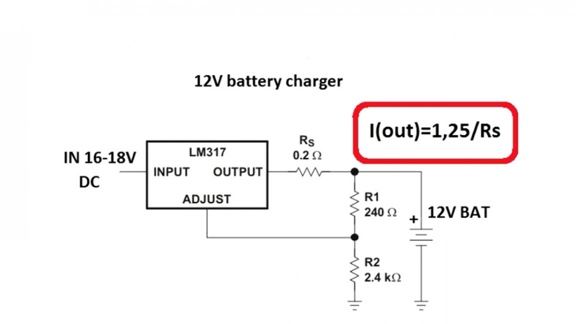
Where 1.25 is the voltage of the reference source of the microcircuit lm317, Rs is the resistance of the current sensor. To obtain a maximum current of 1.5A, the resistance of this resistor should be 0.8 Ohms, but 0.2 Ohm in the circuit.
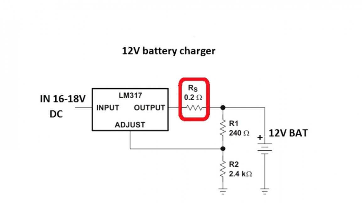
The fact is that even without a resistor, the maximum current at the output of the microcircuit will be limited to the specified value, the resistor here is more for insurance, and its resistance is reduced to minimize losses. The greater the resistance, the more voltage will fall on it, and this will lead to strong heating of the resistor.
The microcircuit must be installed on a massive radiator, an unstabilized voltage up to 30-35V is supplied to the input, this is slightly less than the maximum allowable input voltage for the lm317 microcircuit. It must be remembered that the lm317 chip can dissipate a maximum of 15-20W of power, be sure to consider this.You also need to consider that the maximum output voltage of the circuit will be 2-3 volts less than the input.
Charging takes place with a stable voltage, and the current cannot exceed the set threshold. This circuit can even be used to charge lithium-ion batteries. With short circuits at the output, nothing bad will happen, the current will simply limit and if the cooling of the microcircuit is good, and the difference between the input and output voltage is small, the circuit in this mode can work for an infinitely long time.
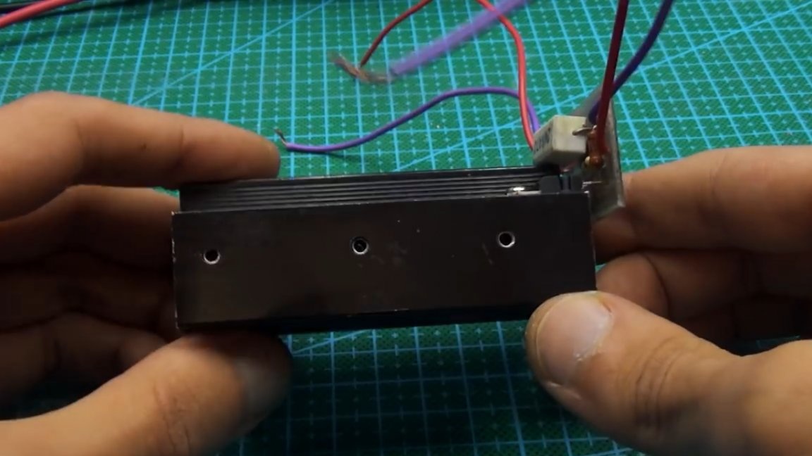
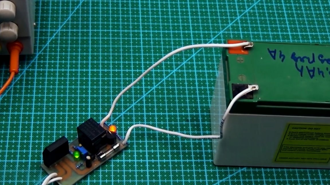
Everything is assembled on a small printed circuit board.
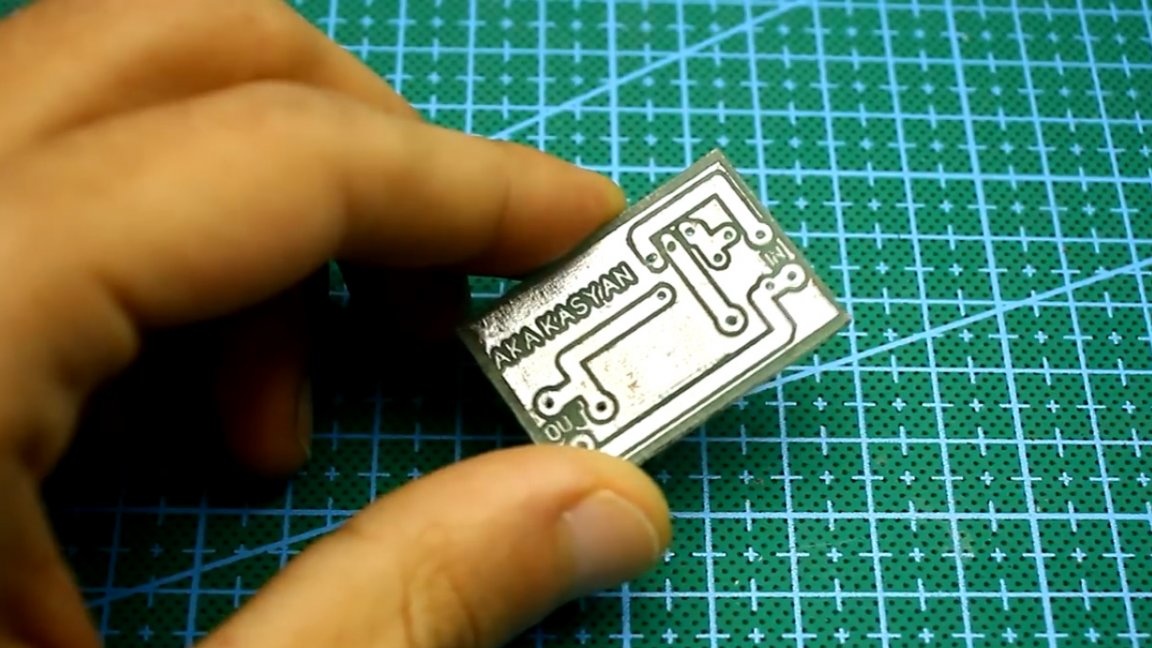
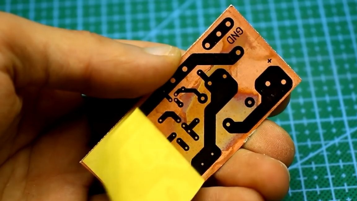
It, as well as printed circuit boards for 2 subsequent circuits, can be together with the general project archive.
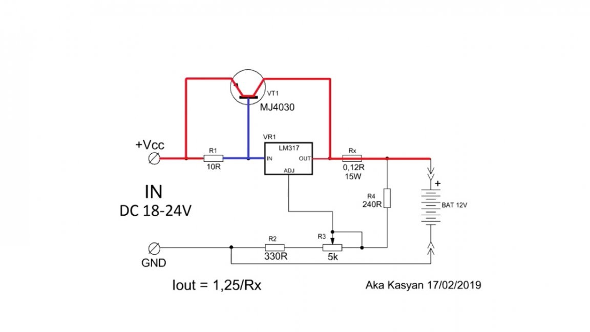
Second circuit It represents a powerful stabilized power source with a maximum output current of up to 10A, was built on the basis of the first option.
It differs from the first circuit in that an additional direct-current power transistor is added here.
The maximum output current of the circuit depends on the resistance of the current sensors and the collector current of the used transistor. In this case, the current is limited to 7A.
The output voltage of the circuit is adjustable in the range from 3 to 30V, which will allow you to charge almost any battery. Adjust the output voltage using the same tuning resistor.
This option is great for charging car batteries, the maximum charge current with the components indicated in the diagram is 10A.
Now let's look at the principle of the circuit. At low currents, the power transistor is closed. As the output current increases, the voltage drop across the indicated resistor becomes sufficient and the transistor starts to open, and all the current will flow through the open junction of the transistor.
Naturally, due to the linear mode of operation, the circuit will heat up, the power transistor and current sensors will be especially hot. The transistor with the lm317 chip is screwed onto a common massive aluminum radiator. It is not necessary to isolate the heat sink substrates, since they are common.
It is very desirable and even necessary to use an additional fan if the circuit will be operated at high currents.
To charge the batteries, by rotating the tuning resistor, you need to set the voltage at the end of charge and that's it. The maximum charge current is limited to 10 amperes, as the batteries charge, the current will drop. The short circuit circuit is not afraid, during short circuit the current will be limited. As in the case of the first scheme, if there is good cooling, the device will be able to endure this mode of operation for a long time.
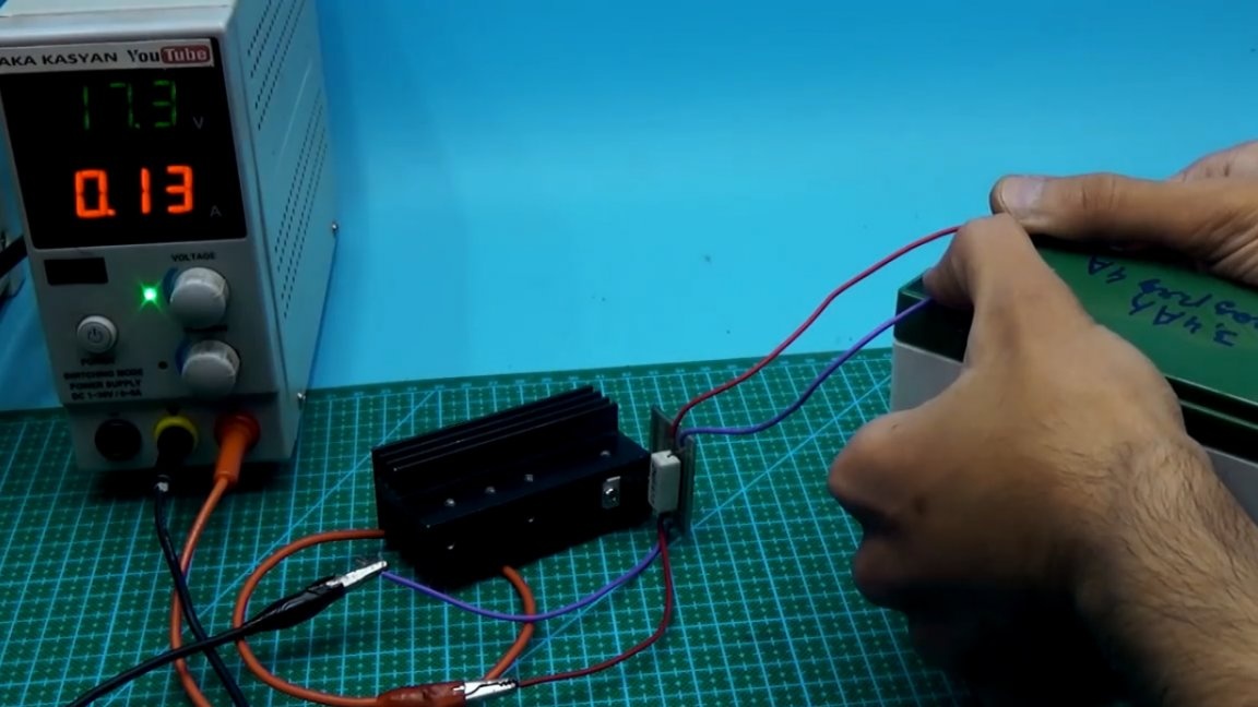
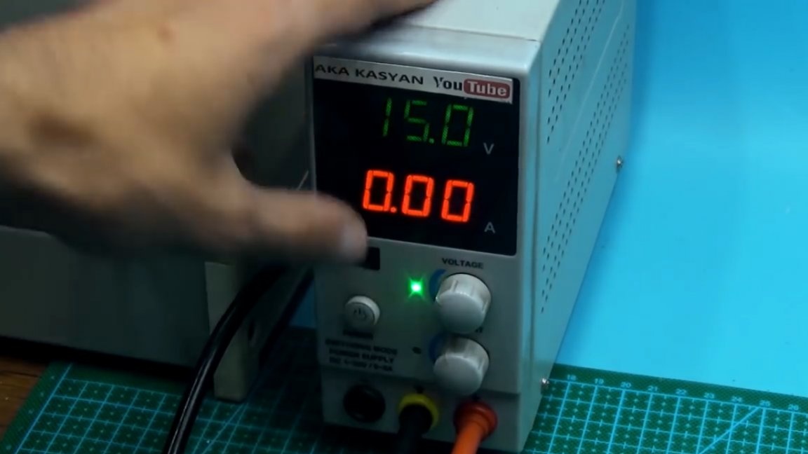
Well, now a few tests:
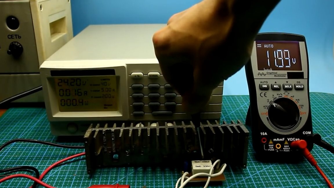
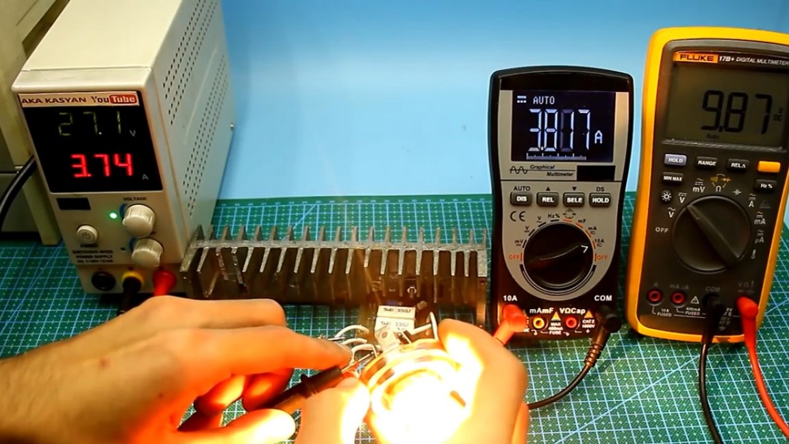
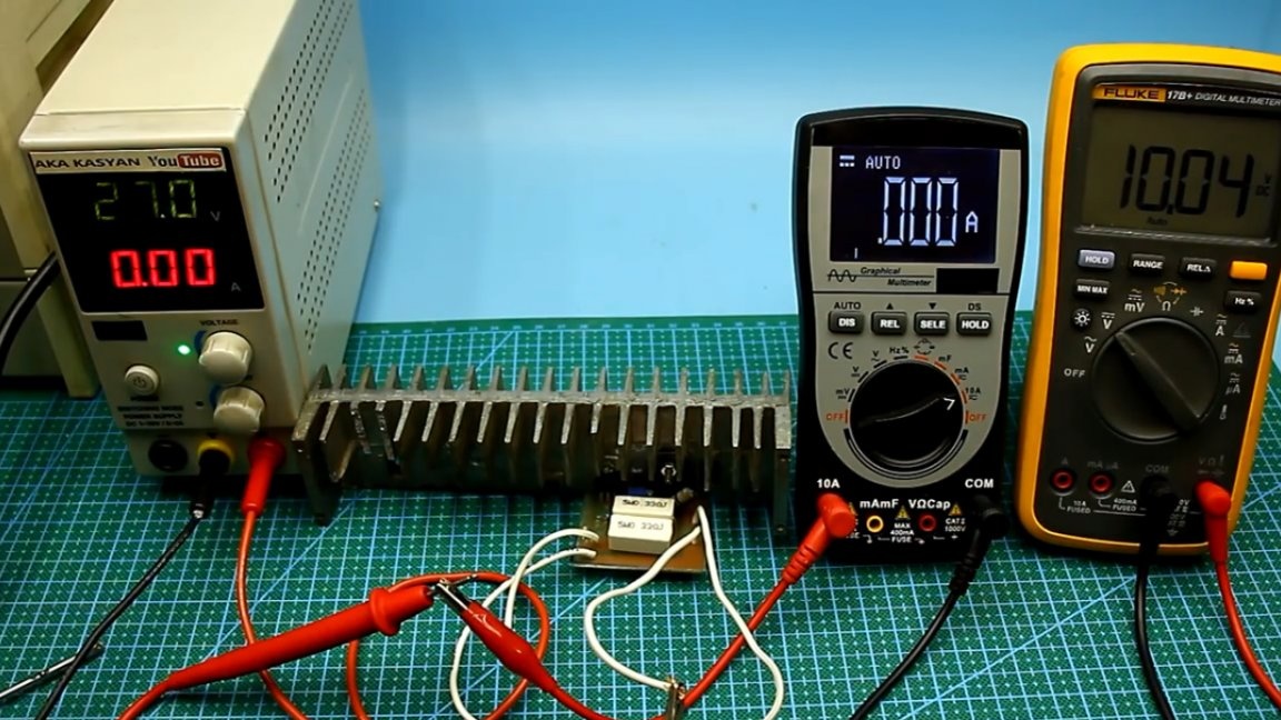
As we see, stabilization is working out, so everything is fine. And finally third scheme:
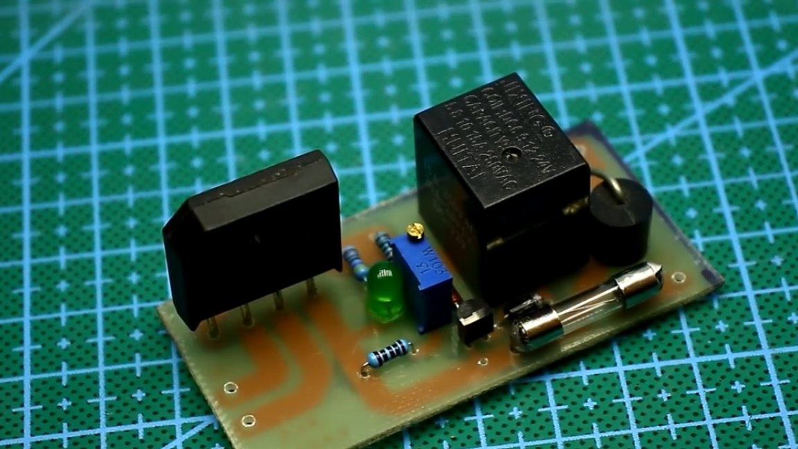
It is a system of automatically turning off the battery when fully charged, that is, it is not quite a charger. The initial circuit was subjected to some changes, and the board was finalized during the tests.
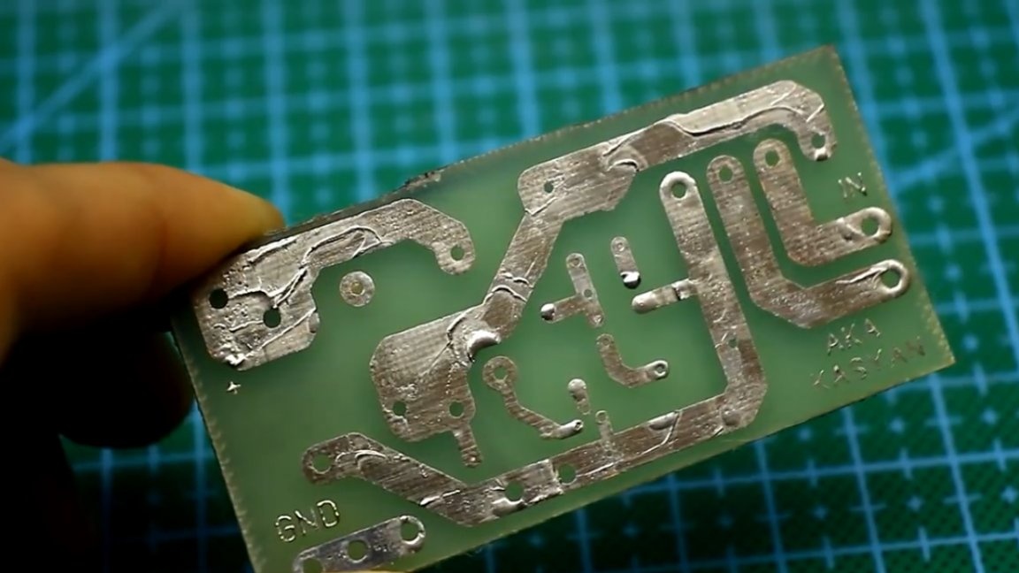
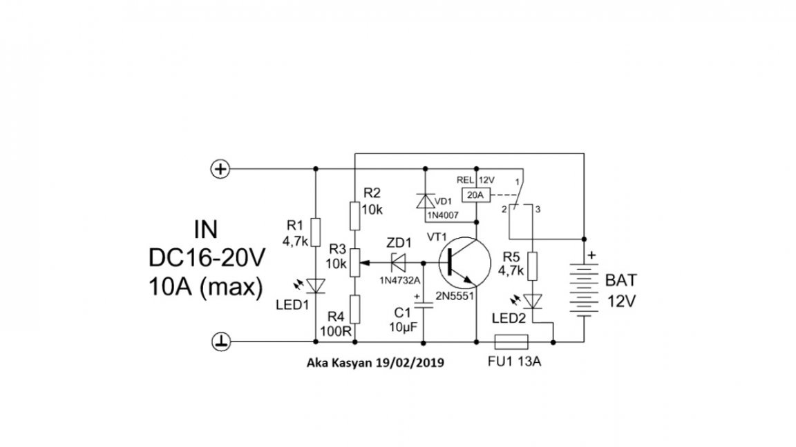
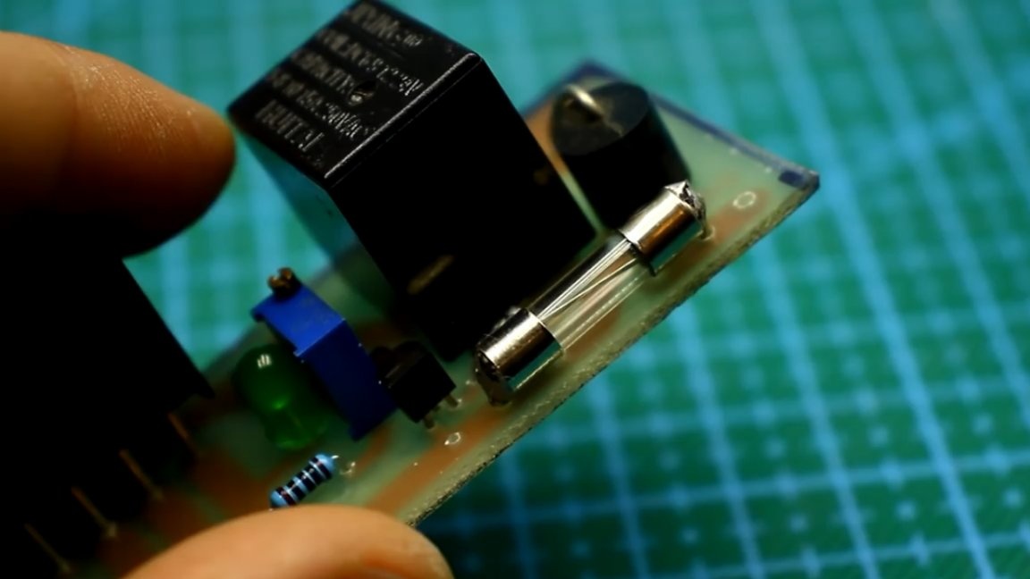
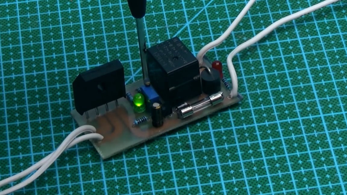
Let's consider the scheme.
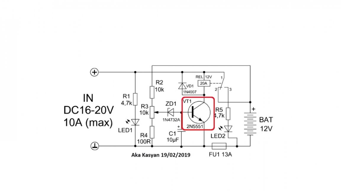
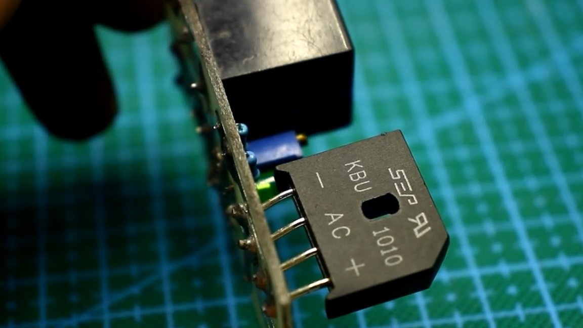
As you can see, it is painfully simple, it contains only 1 transistor, an electromagnetic relay and small things. The author on the board also has a diode input bridge and primitive protection against reverse polarity, these nodes are not drawn on the circuit.
At the input of the circuit, a constant voltage is supplied from the charger or any other power source.
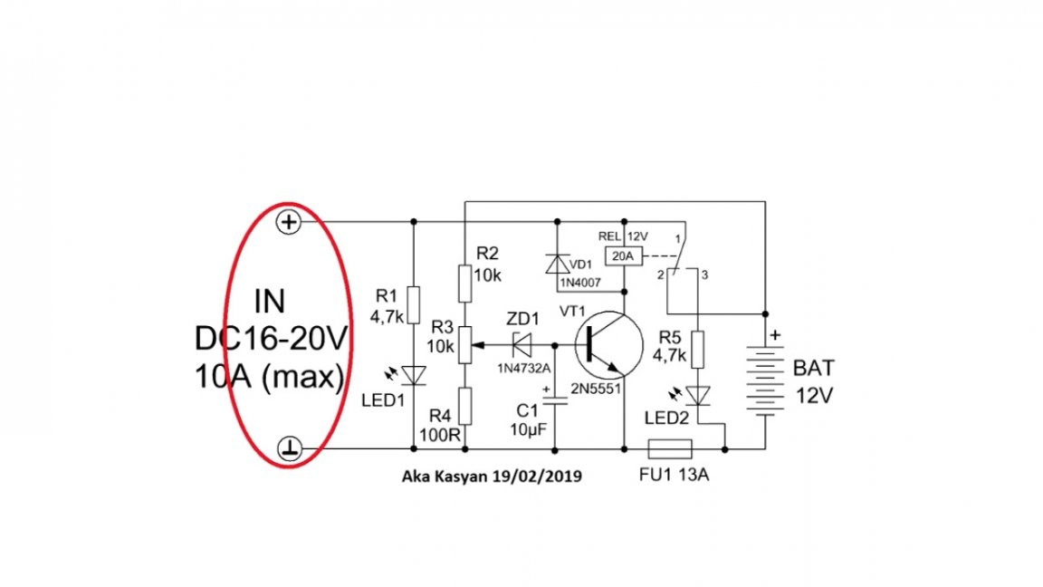
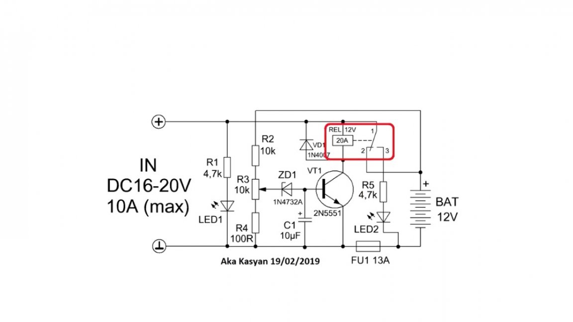
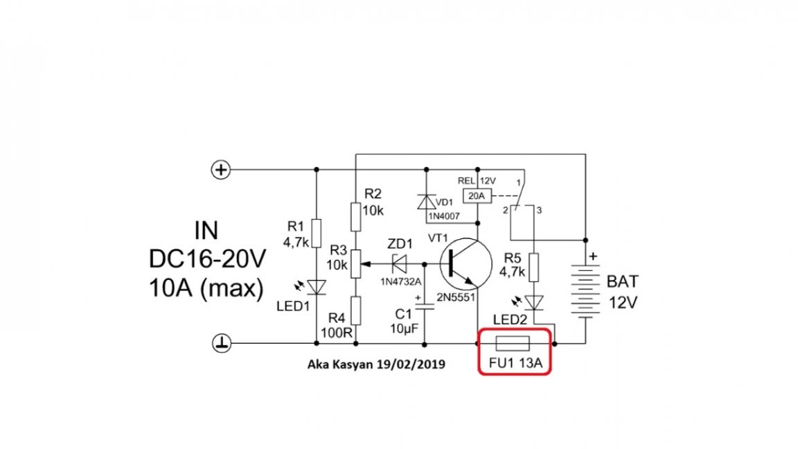
It is important to note here that the charge current should not exceed the permissible current through the relay contacts and the fuse trip current.
When power is applied to the input of the circuit, the battery is charged. The circuit has a voltage divider, with which it monitors the voltage directly on the battery.
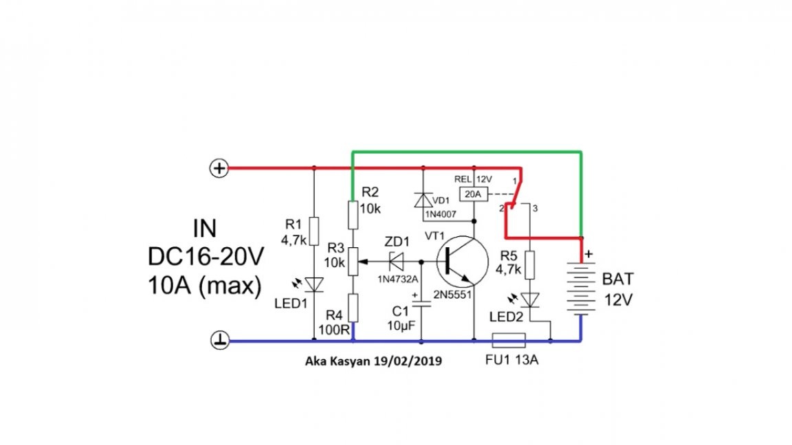
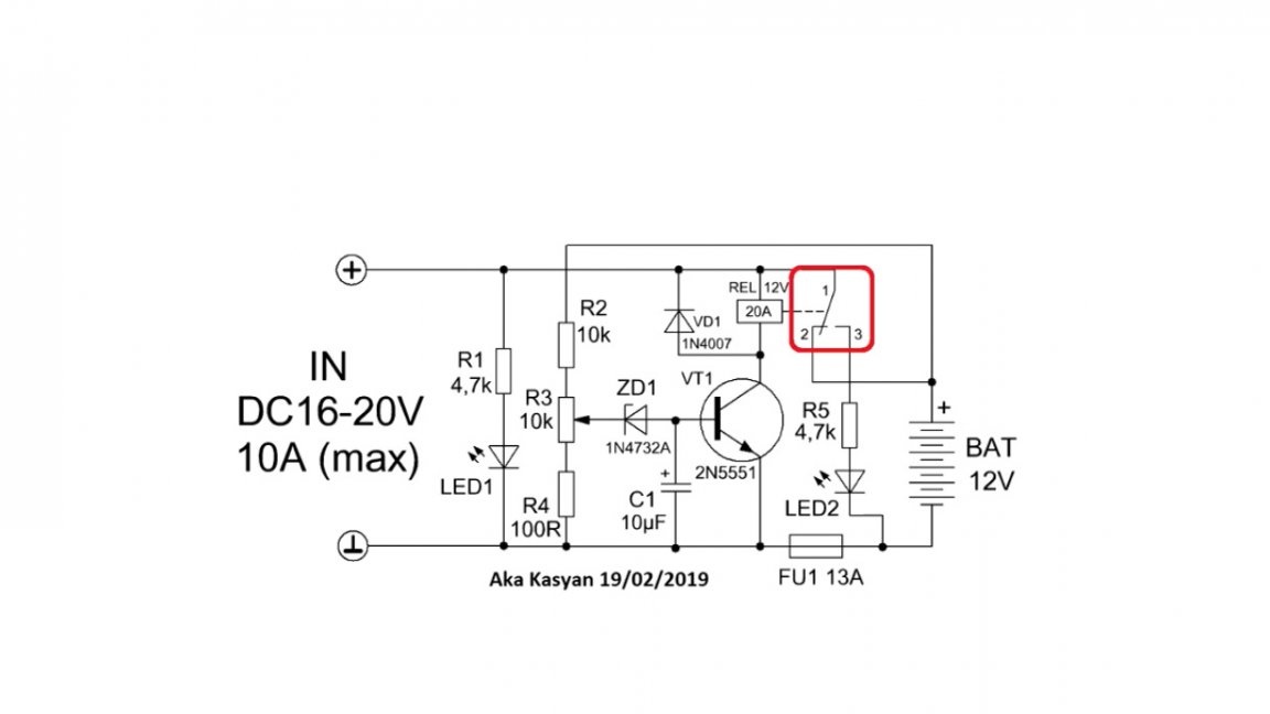
As you charge, the voltage on the battery will increase. As soon as it becomes equal to the operating voltage of the circuit, which can be set by rotating the tuning resistor, the zener diode will work, supplying a signal to the base of a low-power transistor and it will work.
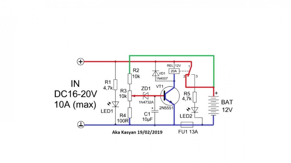
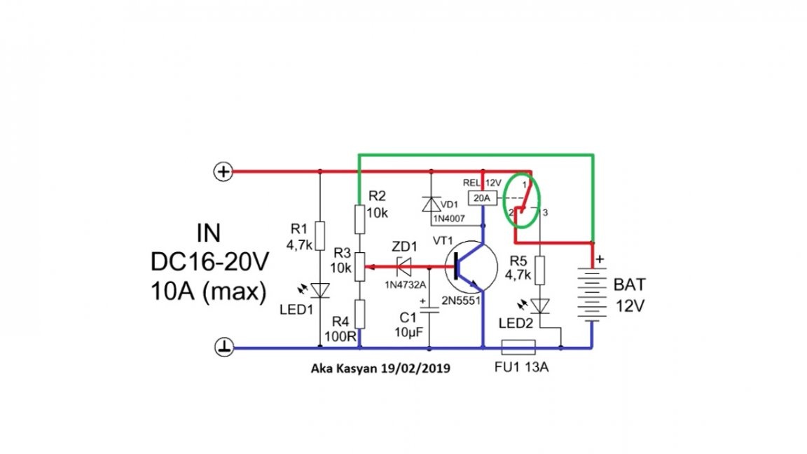
Since the coil of the electromagnetic relay is connected to the collector circuit of the transistor, the latter will also work and the indicated contacts will open, and further power supply to the battery will stop, at the same time the second LED will work, notifying that the charging is completed.
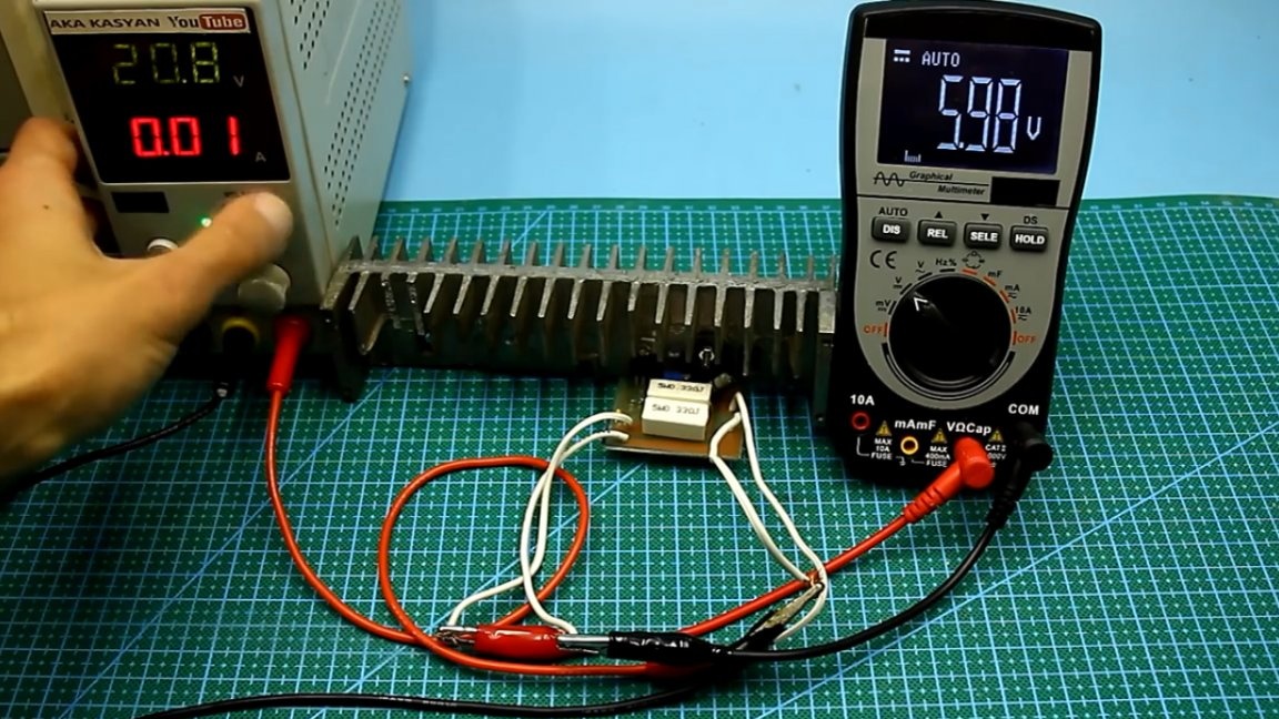
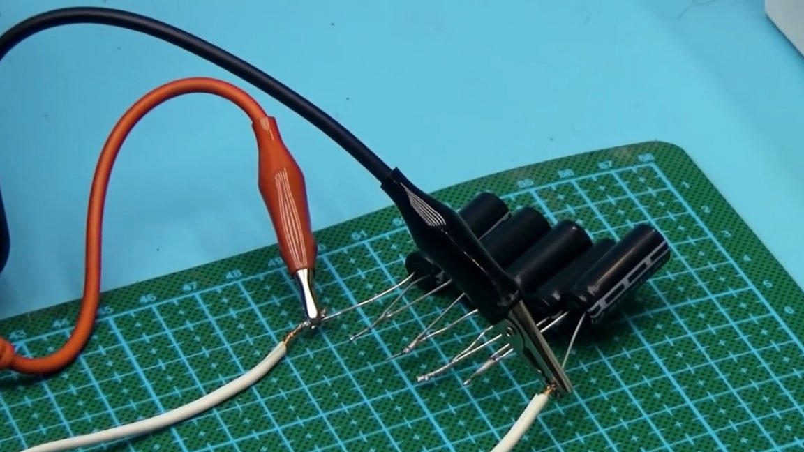
To configure the circuit for its output, a large capacitor is connected, it is in our role as a fast-charging battery. Capacitor voltage 25-35V.
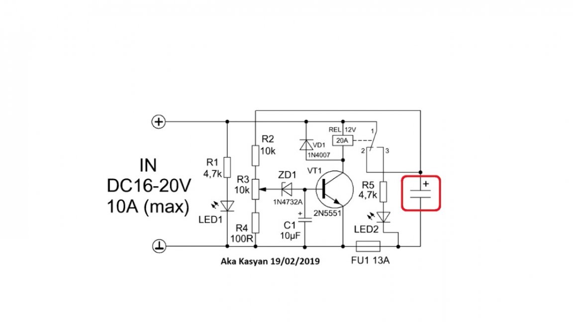
First, we connect the ionistors or capacitor to the output of the circuit, observing the polarity. At the end of the charge, first disconnect the charger from the network, then the battery, otherwise the relay will false. In this case, nothing bad will happen, but the sound is unpleasant.
Next, we take any regulated power source and set it to the voltage to which the battery will be charged and connect the unit to the input of the circuit.
Then slowly rotate the usual resistor until the red indicator lights up, after which we make one full turn of the sub-counter in the opposite direction, since the circuit has some hysteresis.
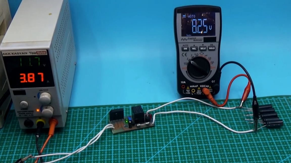
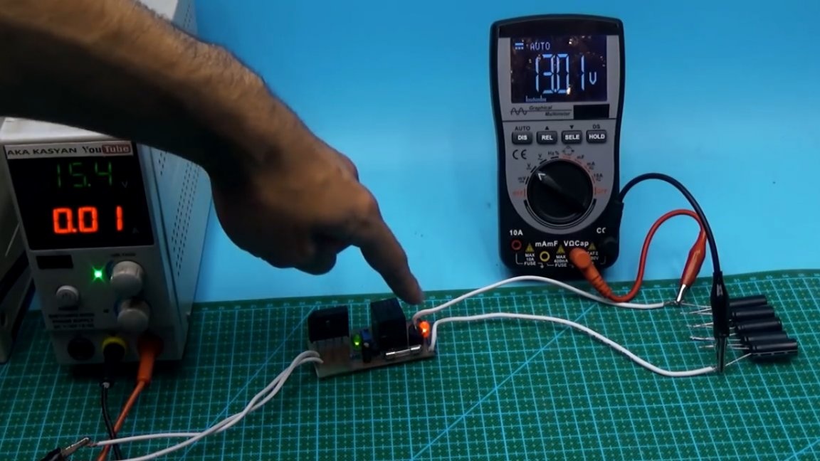
As you can see, everything works. Thank you for attention. See you soon!