

In the circle of rocket-modellers for this node, it is customary to use the term avionics - avionics. I honestly don’t really understand why. In the overwhelming majority of cases, the node is only responsible for triggering the rescue system, if it is cooler, the registration of flight data and video recording. But the concept of avionics has a clear definition: "The Air Force has historically developed a clear division of aircraft equipment (Aircraft) into avionics (AEC), for its work it emits and / or receives radio waves) and aviation equipment (AO). Most AO systems also contain electronic components and components, but do not use radio waves during their operation. "
Based on these definitions, it would be much more logical to use the term aviation equipment, or simply avionics. But avionics so avionics.
Based on these definitions, it would be much more logical to use the term aviation equipment, or simply avionics. But avionics so avionics.
There are many variations and solutions for this task: timers, in which the parachute is ejected after a certain time, which is calculated before the flight, optical tilt sensors (LEDs). But due to the fact that we live in a society and time where sophisticated digital technologies are available to everyone, smart circuits that are capable of measuring height have gained widespread use. Such schemes are built on the basis of altimeters (altimeters), it is also a barometric pressure sensor. As I think everyone knows that the atmospheric pressure is different depending on the altitude. That is why the mountains have a lower boiling point of water and expedition members may experience oxygen starvation. Under ordinary living conditions, a person is not able to catch the difference in atmospheric pressure, these devices are also able to record changes in literally 10 centimeters!
It is one of these devices that I want to describe today. Without a twinge of conscience, I confess that the scheme is not mine. The author of the device is the French rocket-modeller Boris Duro (I hope correctly translated into Russian).
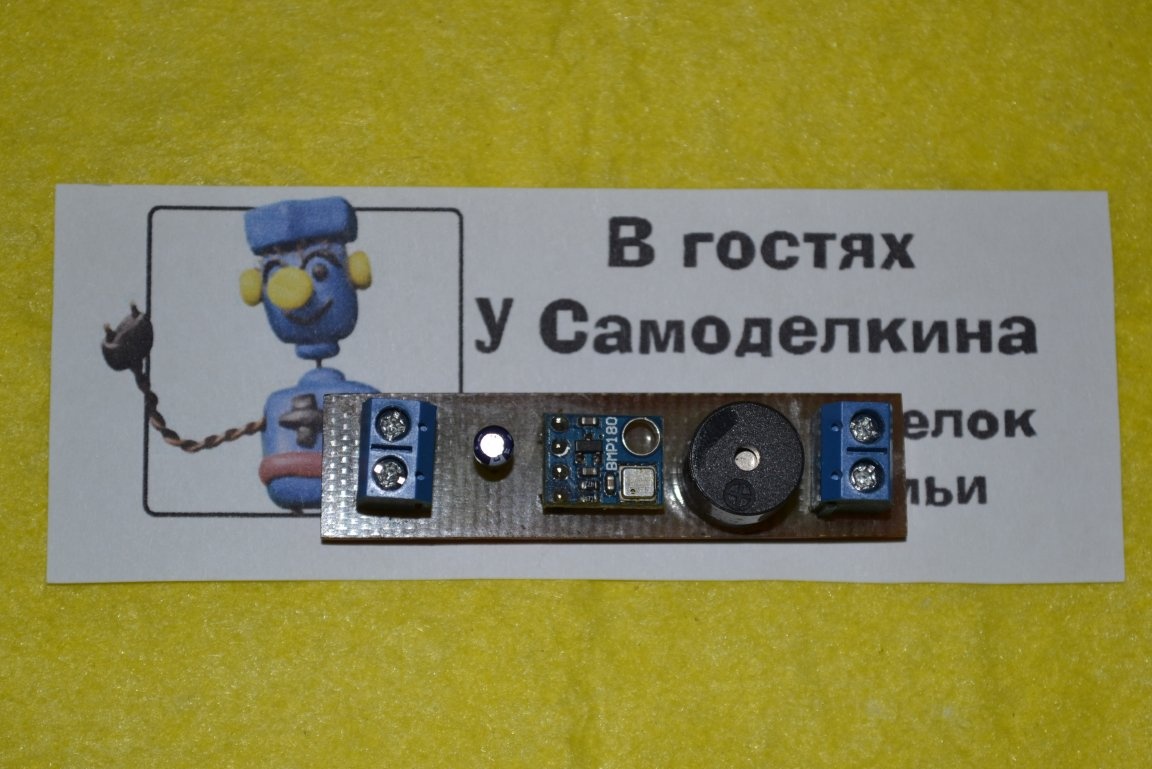
This is the “youngest” device proposed by Boris, nevertheless it has sufficient functionality for a successful start. First, let's go over his work. After switching on, the device is attached to the terrain, checks the integrity of the fuse and emits a signal: intermittent short - in order, intermittent long - damaged. The signal will sound before take-off, regardless of the serviceability / malfunction of the fuse after take-off, the circuit will begin to measure altitude.Take-off is considered to be an elevation of more than 20 meters, upon reaching apogee, the device activates the fuse and, using a simple cipher, continuously rotates the apogee height in a circle. It looks like this: a long signal - 100 meters, a short 10 meters. That is, let's say the device emits 5 long and 3 short signals, which means the apogee height is 530 meters. This "message" is spinning until the device is turned off. Data is not stored in memory, and after switching on, the entire cycle starts anew. Yes, this device does not record flight data, like many of its analogues, but for the first flights this is more than suitable option. In addition, the circuit made on planar components is so small that it is easy to fit even in the smallest children's rocket.
This is the “youngest” device proposed by Boris, nevertheless it has sufficient functionality for a successful start. First, let's go over his work. After switching on, the device is attached to the terrain, checks the integrity of the fuse and emits a signal: intermittent short - in order, intermittent long - damaged. The signal will sound before take-off, regardless of the serviceability / malfunction of the fuse after take-off, the circuit will begin to measure altitude.Take-off is considered to be an elevation of more than 20 meters, upon reaching apogee, the device activates the fuse and, using a simple cipher, continuously rotates the apogee height in a circle. It looks like this: a long signal - 100 meters, a short 10 meters. That is, let's say the device emits 5 long and 3 short signals, which means the apogee height is 530 meters. This "message" is spinning until the device is turned off. Data is not stored in memory, and after switching on, the entire cycle starts anew. Yes, this device does not record flight data, like many of its analogues, but for the first flights this is more than suitable option. In addition, the circuit made on planar components is so small that it is easy to fit even in the smallest children's rocket.
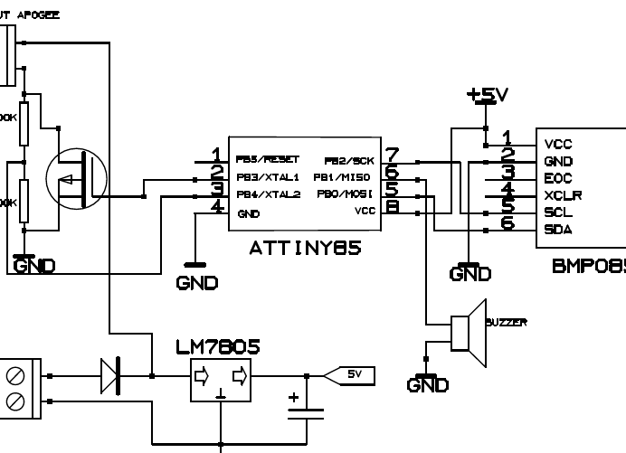
Above you can observe the circuit diagram of the device. The scheme was taken from the site of Boris, but it is worth noting that it has one cant that can be misleading. The diagram shows a graphic designation of a p-channel field effect transistor, when in fact an n-channel is used. Which transistor is not essential to use, any high-current n-channel.
For manufacturing you will need:
- BMP180 Barometer Module
- Attiny 85 microcontroller
- Electrolytic Capacitor 47 mF, 16 V
- 100 kΩ and 2 kΩ resistors
- 78L05 stabilizer in TO92 housing or equivalent in SMD
- High current field effect transistor IRF540 / IRFZ44 or equivalent in SMD version
- Pads for wires 2 pcs.
- 5 V active buzzer
- Diode 1N4001 or 1N4007. Optionally, it is a protection against overtaking.
- Textolite
From the tool:
- Soldering iron
- Tweezers
- Side cutters
- Solder
- Flux
- USBasp Programmer
In the archive below are two files of the circuit board, for SMD components and for conventional output wiring. I must say right away that I did not collect the second board, I did it in SMD, but for those who for some reason cannot solder small planar components, I made a trace for ordinary components. Nevertheless, I checked several times, it should be error free.

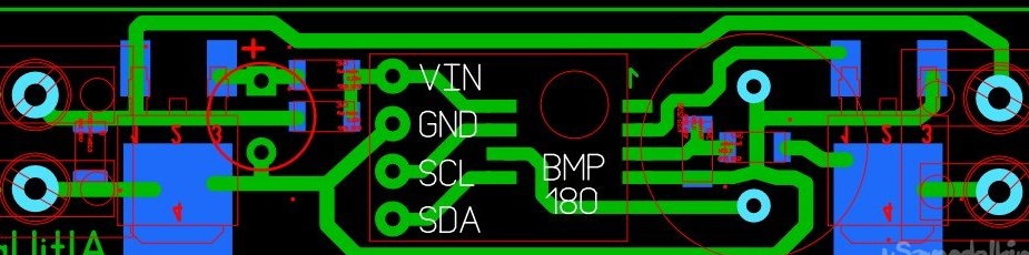
And so, the first thing we do is make a printed circuit board. I, as usual, did LUT.
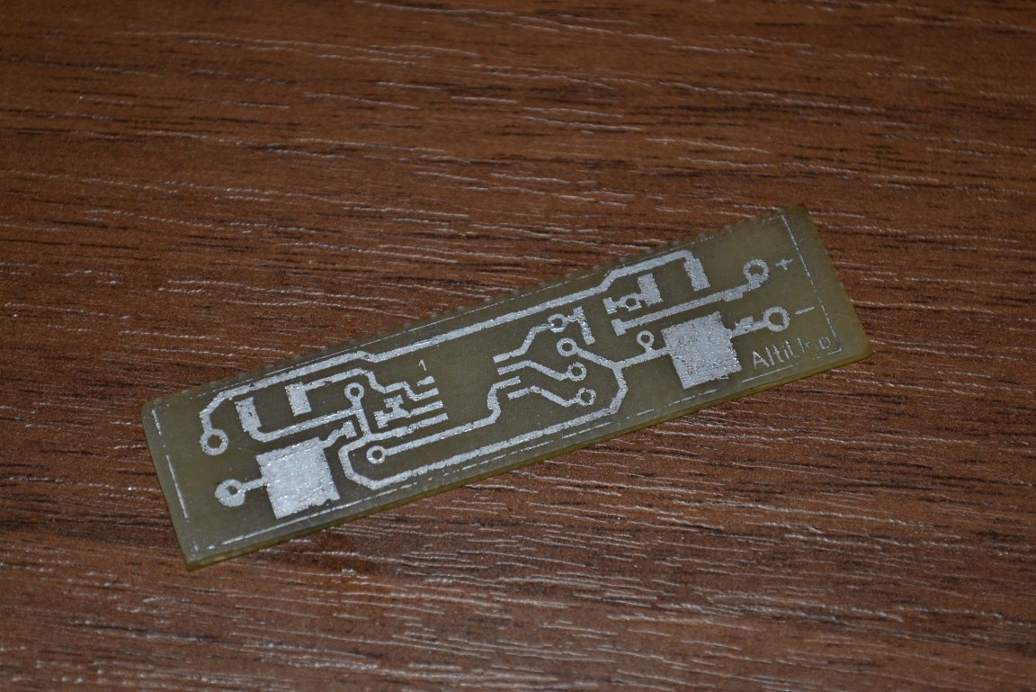
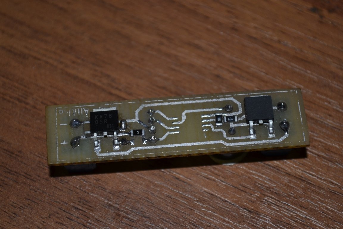
And solder all the SMD components except the controller.
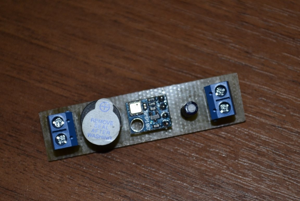
Next, solder the buzzer, sensor, pads and capacitor.
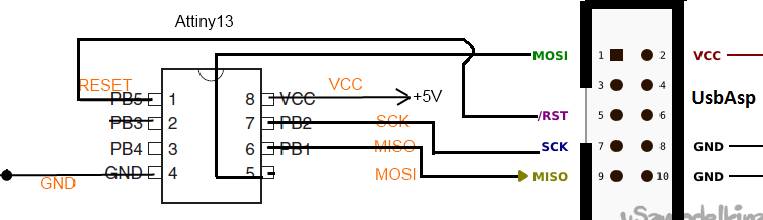
Now you need to flash the controller. The firmware for this circuit is written in an arduino environment, so you need to fill in the Arduino bootloader into the controller. This is done through the USB ASP programmer directly from under the arduino programming environment itself. First of all, you need to connect the controller to the programmer itself. The connection diagram is below.
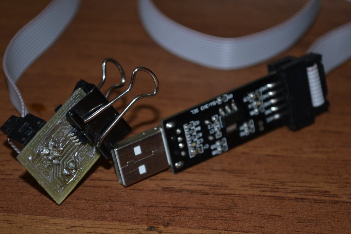
To connect the controller in SMD version, an adapter is required.
The file with the printed circuit board is also in the archive at the end of the article. Now let's move on to the software improvements. First you need to make friends Arduino IDE with Attiny 85, because out of the box this controller is not supported. To do this, at ... / Arduino / hardware you need to create a tiny folder in which to place the contents of the archive with the kernels. You can download the archive this linkDownload the latest version. Now the environment will be able to see the controller. We connect the programmer, open the arduino environment, go to and put USBasp.
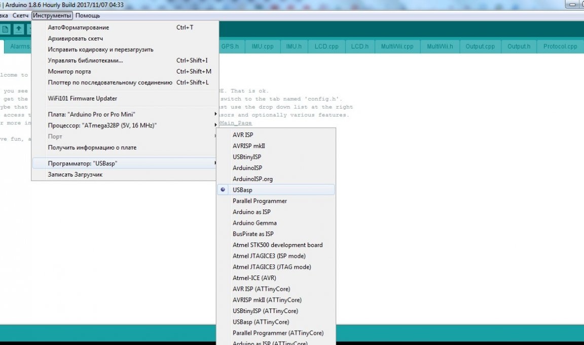
Now select ATtiny25 / 45/85.
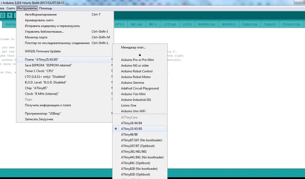
We look that ATtiny85 would stand in Chip. Now all in the same tools click. If everything is done correctly, there are no problems with the contact, there are no problems with the drivers, then the environment will report a successful recording. A huge plus in this firmware is that you don’t need to bother with fuses, the Arduino environment will do everything itself. So you won’t kill the controller. After that, you can fill in the sketch. The sketch is poured in almost the same way as usual, but instead of the usual button you need to go to. That's all, now you can solder a tink into the board.

Now let's move on to the features of my circuit board. I made an avionics compartment for installing a 18650 battery in it.As you know, a fully charged single-bank li-ion battery produces 4.2 volts, the lower threshold of the supply voltage for Attiny 85 is 2.7 volts, the critical discharge level for such a battery, that is, as you understand, the power is enough with your head. BUT! Only if you apply power directly bypassing the stabilizer. I did not begin to remove the stabilizer from the circuit, in order to make it more universal, even if it is not involved with me. And so, there are five on the board for two resistors.
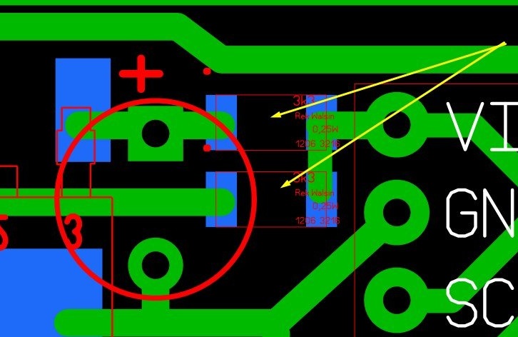
These are not really resistors. On one pair of these heels you need to solder a jumper, the so-called zero resistance (you can stupidly a piece of wire). If you, like me, will feed the circuit from such a power source, then solder to the lower contacts, if you look at the picture, if you intend to use for example a crown, then to the upper, to the output from the stabilizer. On the printed circuit board, actually everything is visible, what and where is going.
On the board for output components, this option is not provided. You can either finish the signet yourself, adding for example a couple of jumpers, or just do not solder the stabilizer and solder the jumper.
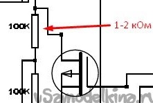
Another nuance. When powered by a battery with a voltage of 4.2 volts, it may happen that the transistor is constantly open. As you can see from the diagram, there is a divider between the drain and the source. To solve the problem, you need to replace one of the resistors with 1-2 kOhm. Which one is shown below.
On the board for output components, this option is not provided. You can either finish the signet yourself, adding for example a couple of jumpers, or just do not solder the stabilizer and solder the jumper.
Another nuance. When powered by a battery with a voltage of 4.2 volts, it may happen that the transistor is constantly open. As you can see from the diagram, there is a divider between the drain and the source. To solve the problem, you need to replace one of the resistors with 1-2 kOhm. Which one is shown below.
Now for the firmware. There are 2 firmwares in the archive, the main one for triggering the electric fuse of the rescue system, and an alternative one. Alternative firmware allows you to use the circuit as a sound search beacon. Since the circuit is very compact, it can be placed in the head fairing of the rocket, choosing a compact power source. To do this, instead of a fuse, a powerful piezo emitter is connected to the contacts, similar to that shown below.
Someone will say why, on the board there is a buzzer. Yes, but no matter how loud it may seem to you during tests in the room, in fact, you can hear a ceiling of about 20 meters in the field. In general, search engines for models are a whole epic. In future plans, I have an assembly of GPS beacon, which will determine the coordinates and sends them on the air. Coordinates are received on a portable radio station (walkie-talkie), and using any phone (now all have a GPS navigator), a model is searched. But it is in the plans, we will return to reality.
Although, in principle, there’s nothing special to return to. A special chassis is made for the board, thanks to which it is mounted in a rocket. The chassis is made specifically for your model. I made it from the thinnest hairpins that I could buy in a construction store, and pieces of home-made fiberglass.
Although, in principle, there’s nothing special to return to. A special chassis is made for the board, thanks to which it is mounted in a rocket. The chassis is made specifically for your model. I made it from the thinnest hairpins that I could buy in a construction store, and pieces of home-made fiberglass.
The board is attached to the chassis on ordinary stationery rubber bands. It is easy to install and works like a shock absorber so that the sensor does not go crazy.
As you can see the board from the side of the tracks I painted depressed nail polish, for greater protection, so to speak. From the end of the chassis, I decided to attach a charge module, at one time I bought a couple of dozen on Ali, they cost like seeds, so it’s not a pity.
A few words about the verification. We take a jar (such that the circuit with power fits) and a nylon cover. We make a hole in the lid and hermetically paste the tube from the dropper into it. The other end of the tube is connected to a syringe of cubes of 20. We put the device in a jar, close and pump out the air with a syringe. After we supply air back.
The second option. On the advice of a familiar modeler. We take a tube from a lollipop, a rod of a pen, an ear stick. We wind several layers of electrical tape at the end so that the electrical tape extends beyond the tube a few millimeters. Carefully with a sharp mounting knife, cut off the edge of the wound tube, which would be even. We apply it evenly to the hole on the sensor itself and sharply draw out the air with our mouths. Primitive, but it works.
The second option. On the advice of a familiar modeler. We take a tube from a lollipop, a rod of a pen, an ear stick. We wind several layers of electrical tape at the end so that the electrical tape extends beyond the tube a few millimeters. Carefully with a sharp mounting knife, cut off the edge of the wound tube, which would be even. We apply it evenly to the hole on the sensor itself and sharply draw out the air with our mouths. Primitive, but it works.
And a few words, for those who have a question, how is the climax determined. In all such devices, this is implemented the same way. When flying, the current altitude is constantly compared with the previous one. As soon as this value begins to fall below the previous one (the rocket began to fall), it is fixed by the apogee. But in order for there to be no false positives, the apogee is considered to be a rocket drop to a certain height, usually a drop of 3 meters (this is correct in the code), but for higher-flying missiles they put more.
All necessary files can be downloaded from.
That's all. Video with a poster demo below. All success in the work!