
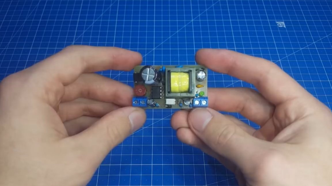
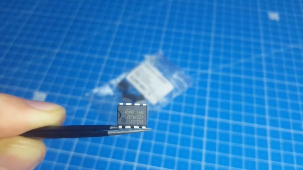
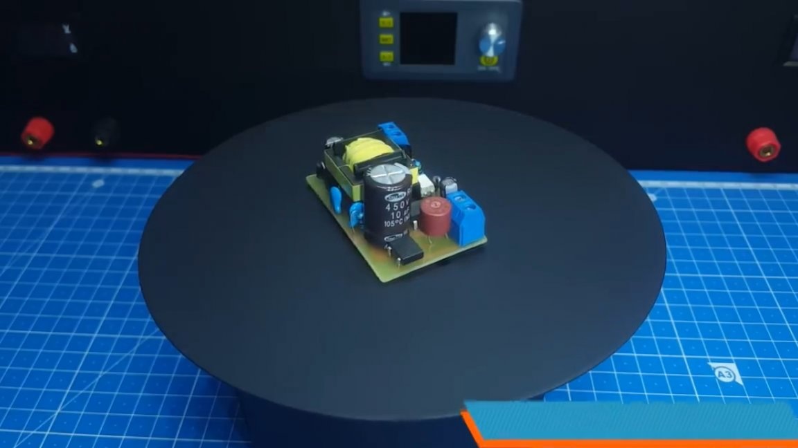
Today, together with Roman, the author of the YouTube channel “Open Frime TV”, we will assemble such a miniature power supply unit on the VIPER 22A chip.
First of all, let's talk about why such a power supply is needed. Basically, the author plans to use it as a food on duty in more powerful units in order to exclude self-power and microstart from the circuit.
Yes, we will lose a little in the size of the board, but setting up the entire device will be much simpler. Also, this unit can be used as a charger or as a power supply for some low-current consumers. Output power can reach 15W.
The second reason for the assembly is the desire to understand the reverse-running converters, and the author decided to start with such a block. Of the advantages, he has the fact that the power and control part of the circuit are in the same microcircuit and we can only wind the transformer and part the board, which is very convenient for a beginner.
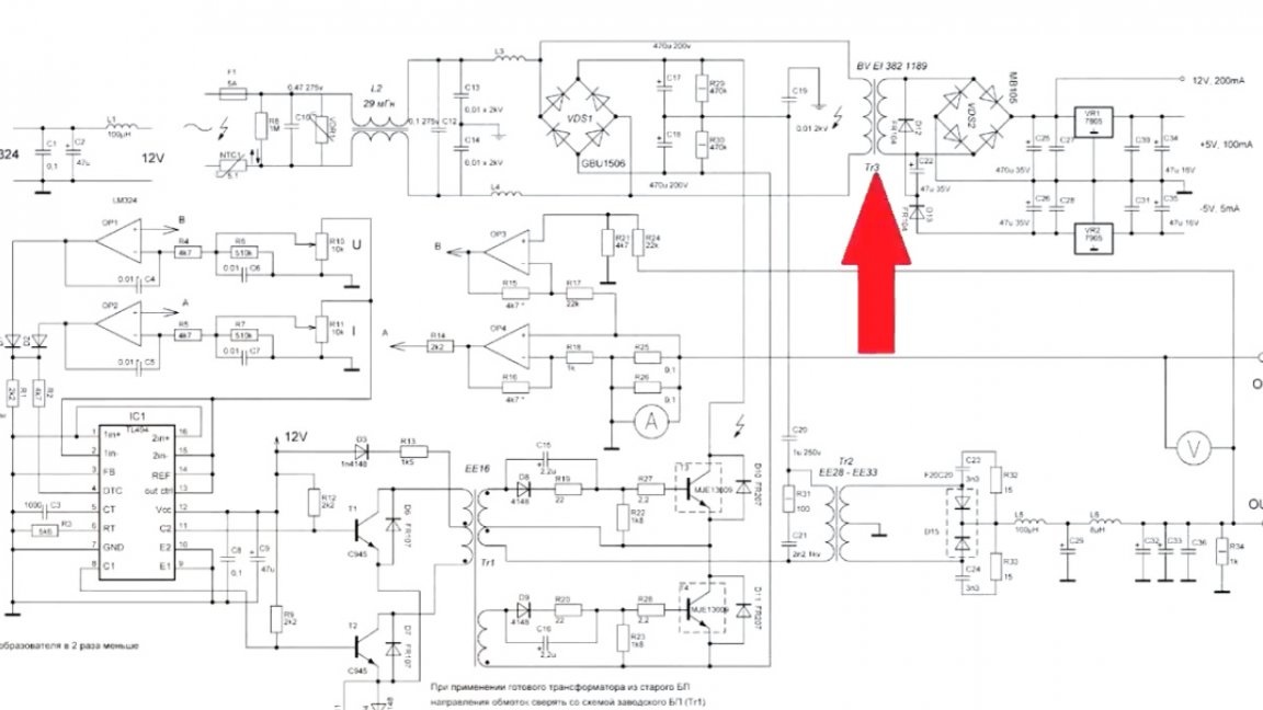
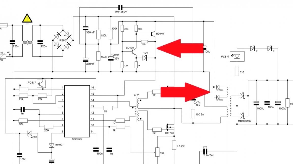
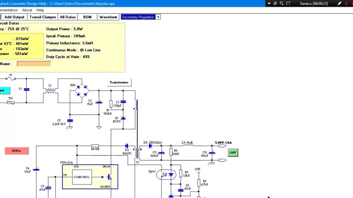
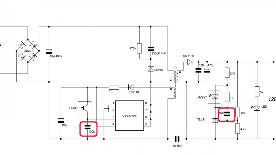
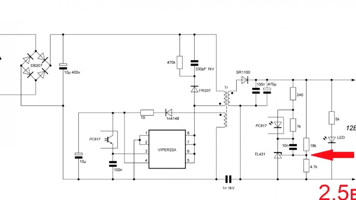
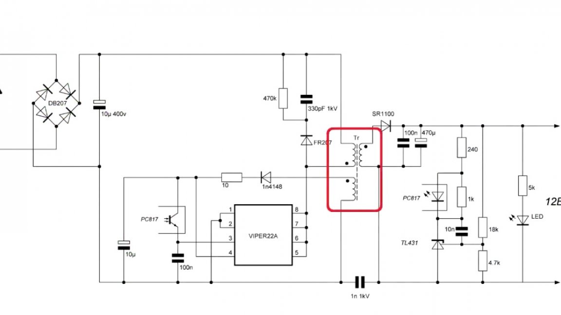
Let's get started on the build. First consider device diagram:
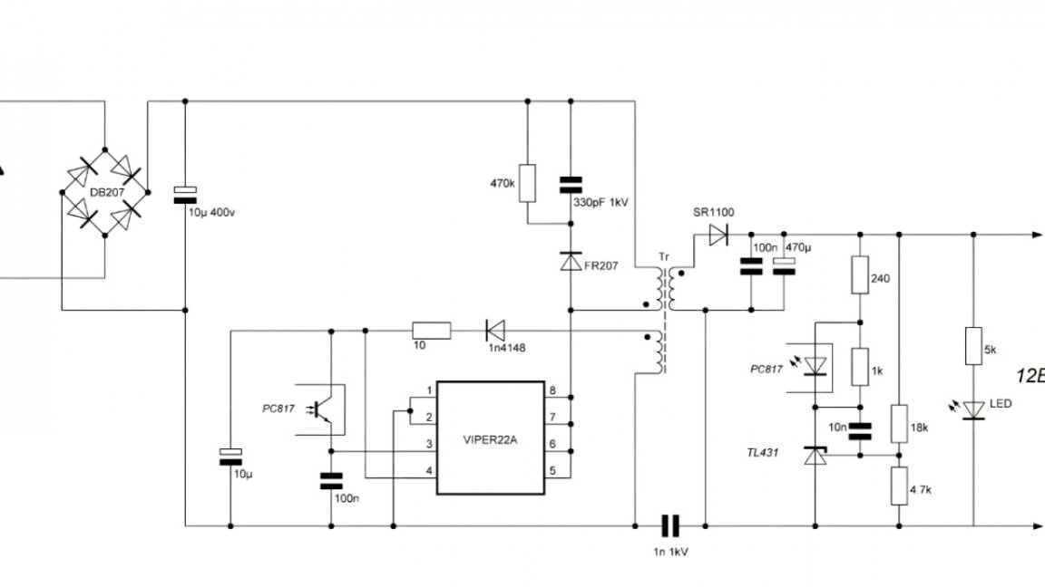
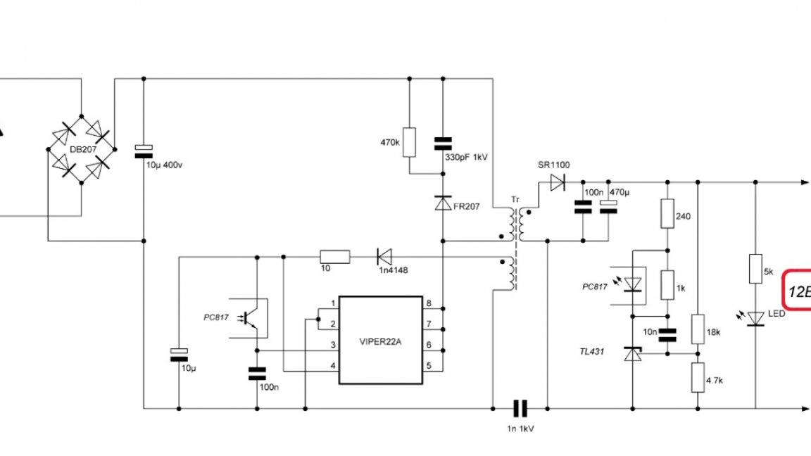
As you can see, it is designed for 12V and a current of 0.5A.
But what if we need other output specifications? For this, the developers wrote a special program in which you can set the required output voltage and current, and she herself selects the ratings.
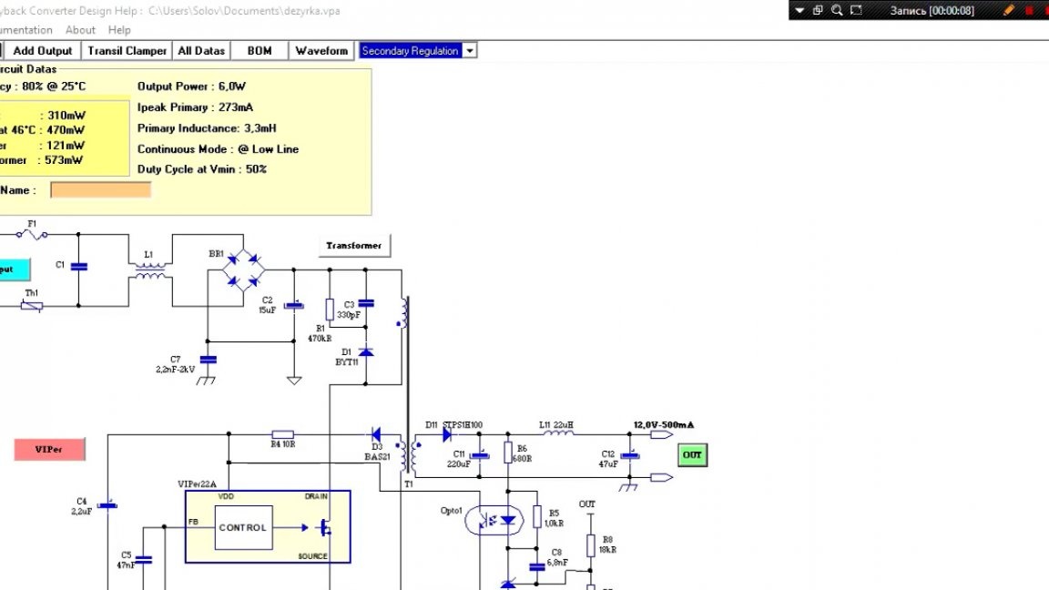
For example, we can set the voltage to 5V and the current to 1A, as for a charger. At the output, we get these values:
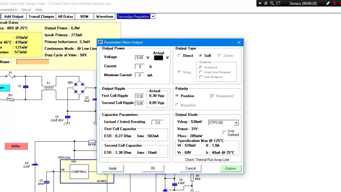
In principle, everything is fine here, except for these Conders:
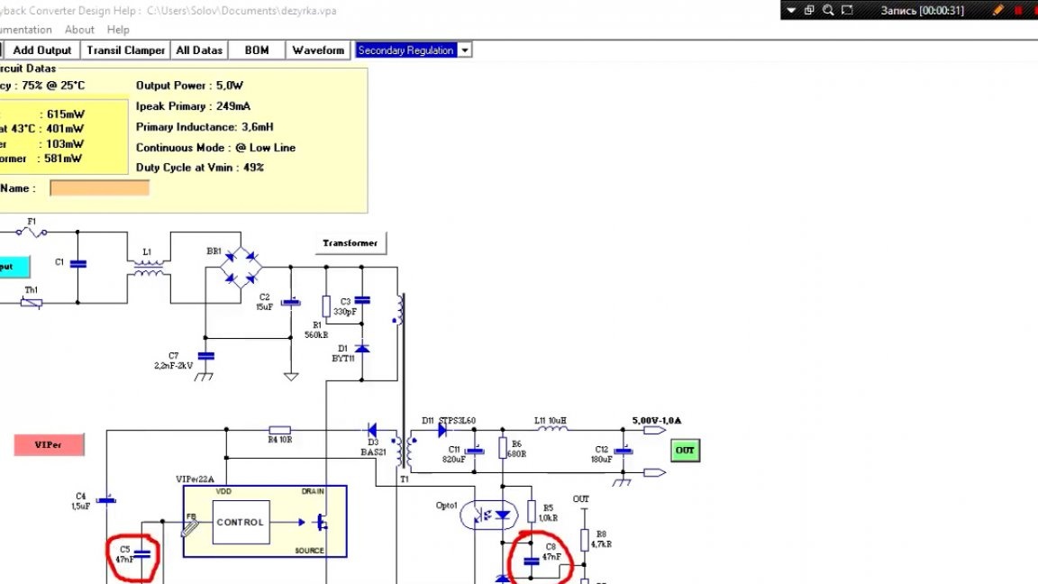
They depend on how you wind the transformer. In this case, I had to pick them up, because at standard ratings a small squeak was heard, which was very annoying. We also see that the program gave us the necessary values of the divider for tl431.
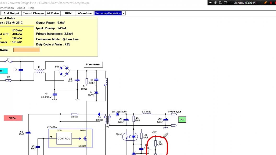
They are calculated in such a way that at the rated output voltage at the divider point it was 2.5V.
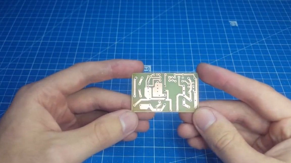
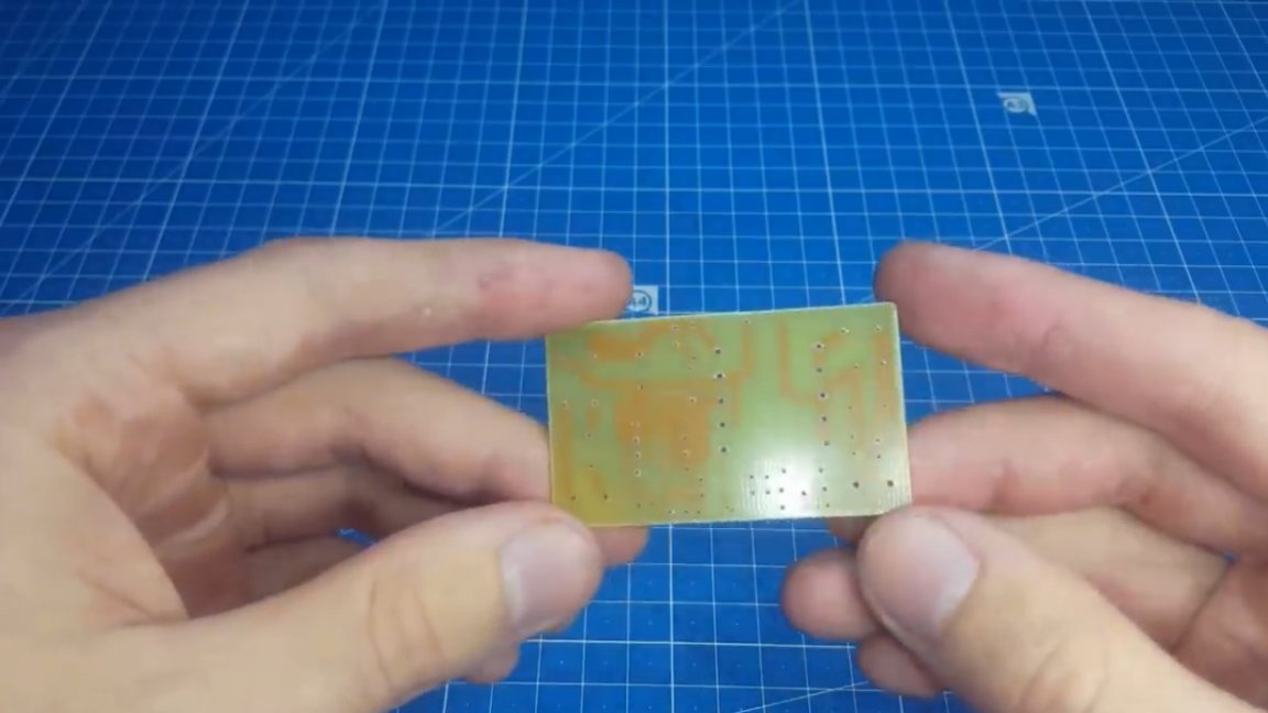
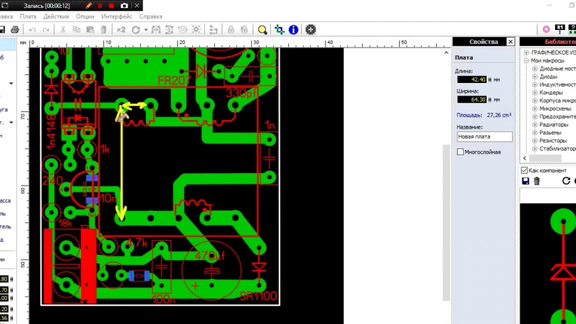
When we received all the ratings, we proceed to the layout of the printed circuit board.
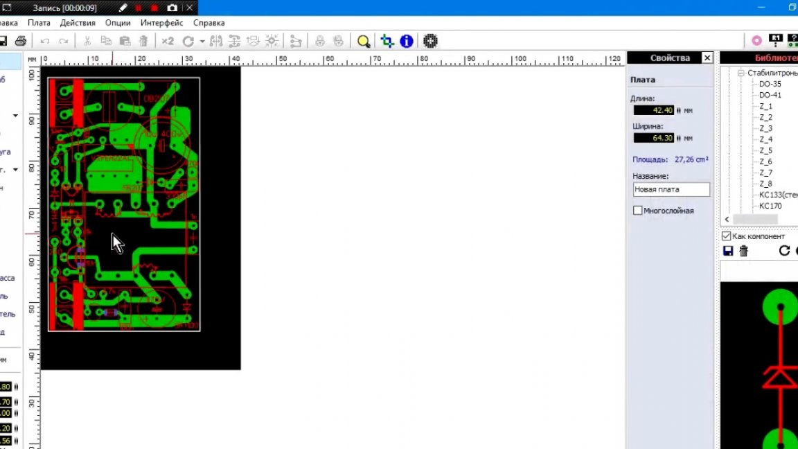
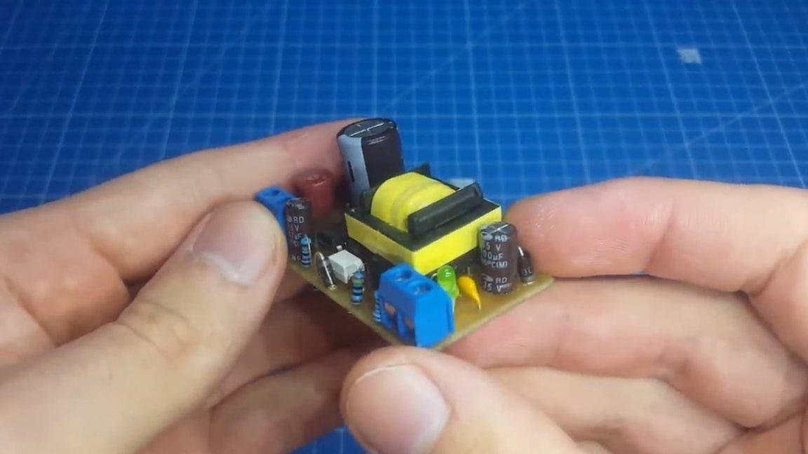
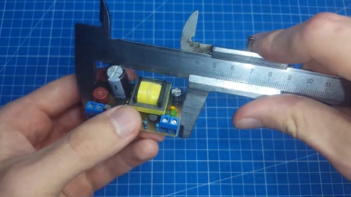
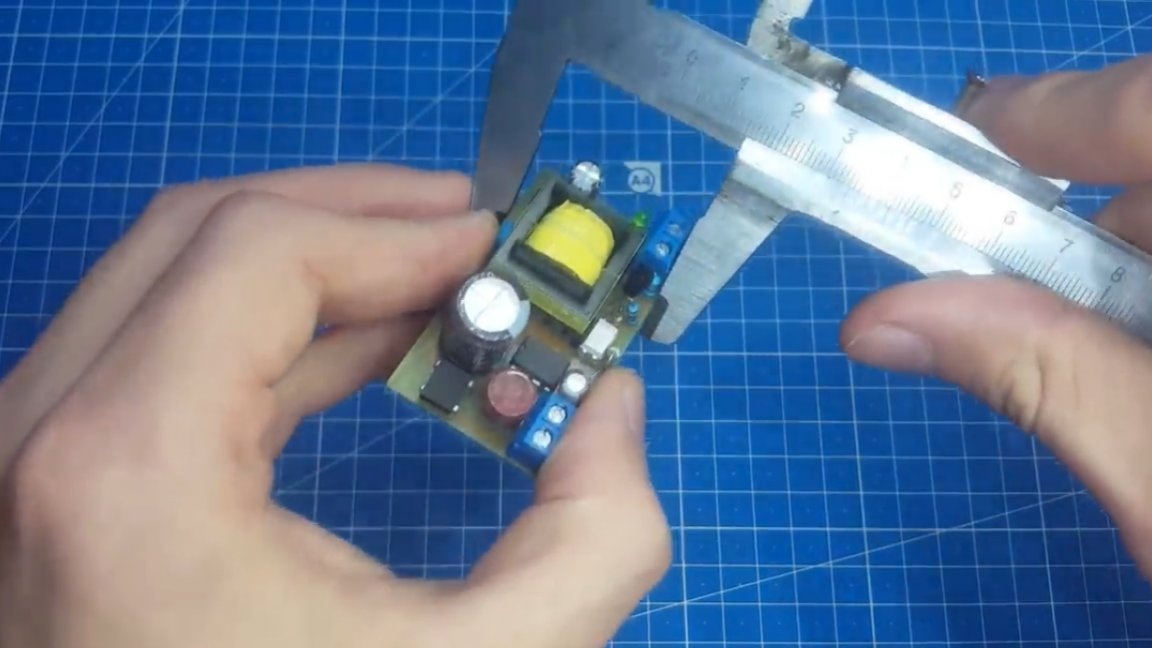
As you can see, it turned out to be miniature and there are only 2 smd elements.
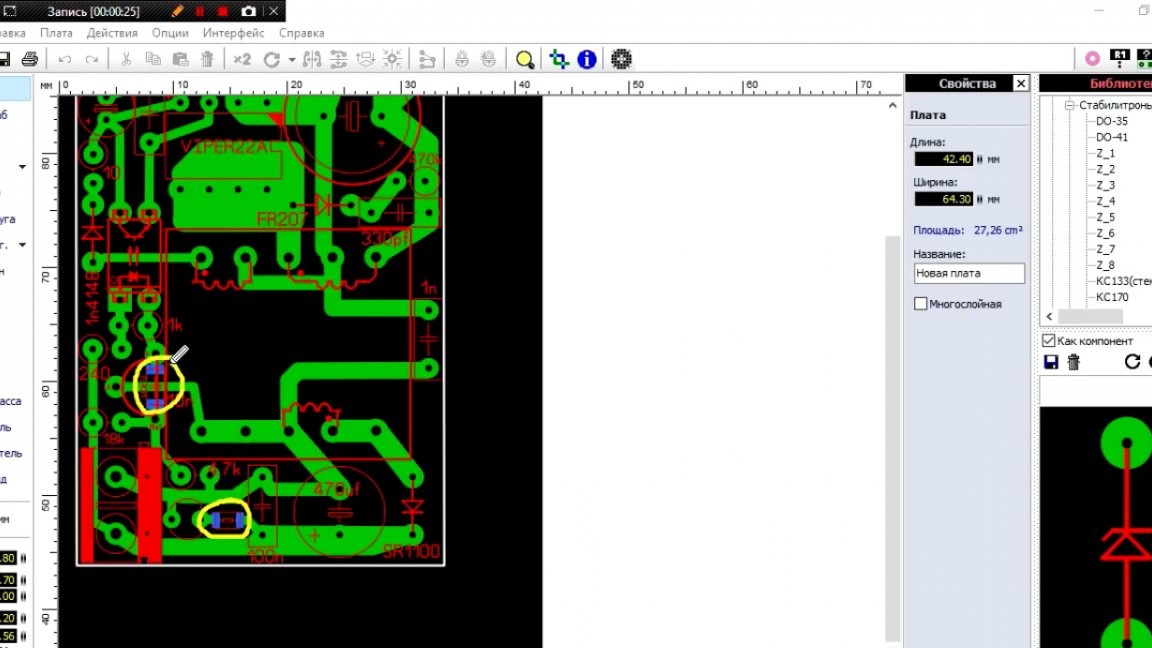
The first is the resistor for the LED, which must be selected depending on the voltage, and the second is the capacitor near tl431, when tracing, the author simply forgot about it, and when he remembered it was too late, so you have to buy an smd capacitor or re-design the board.
You could also pay attention to the landfill near the chip.
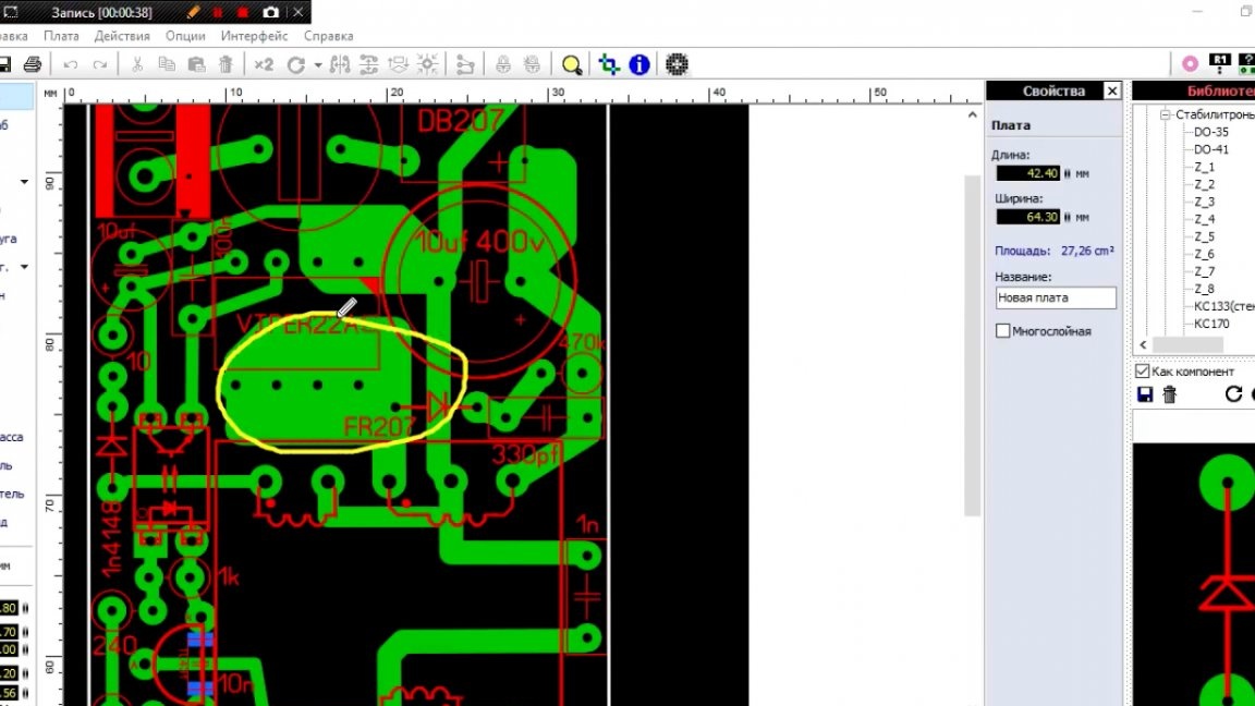
This is the so-called improvised radiator, since the chip removes heat only using its findings.
Now the most difficult part of the circuit is the transformer, or rather, it is a choke, but it is more common to call it a transformer.
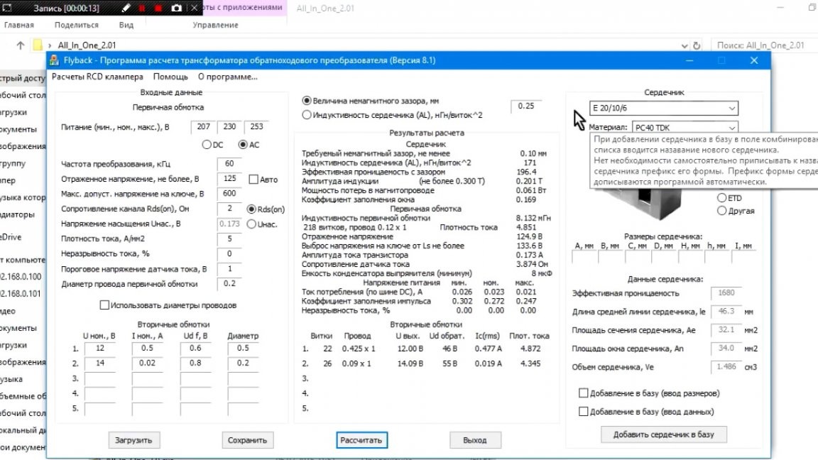
Calculation can be made in the factory program:
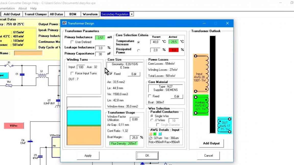
But, as we see, everything is confused there, plus the diameters of the wires in another measurement system. In general, the author recommends using the Starichka program, since it is much more convenient.
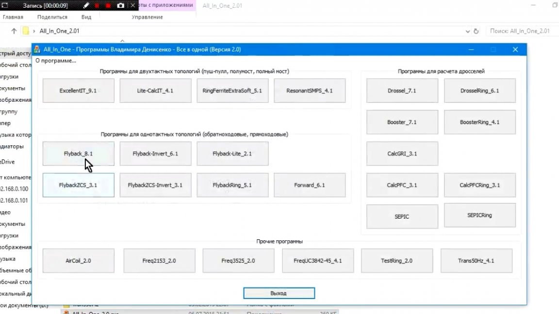
In it we select the core, here you can use a rather popular core from the ATX standby power supply unit - e16.
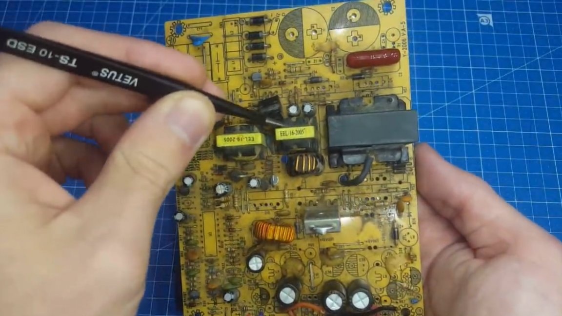
The author also used the e20 core, since only such were on the market.
If you use another core, just change the distance between the legs on the circuit board, that's all.
So, then we indicate the parameters of the windings, as well as the diameter of the wire that is available, and the program gives us the parameters of the winding.
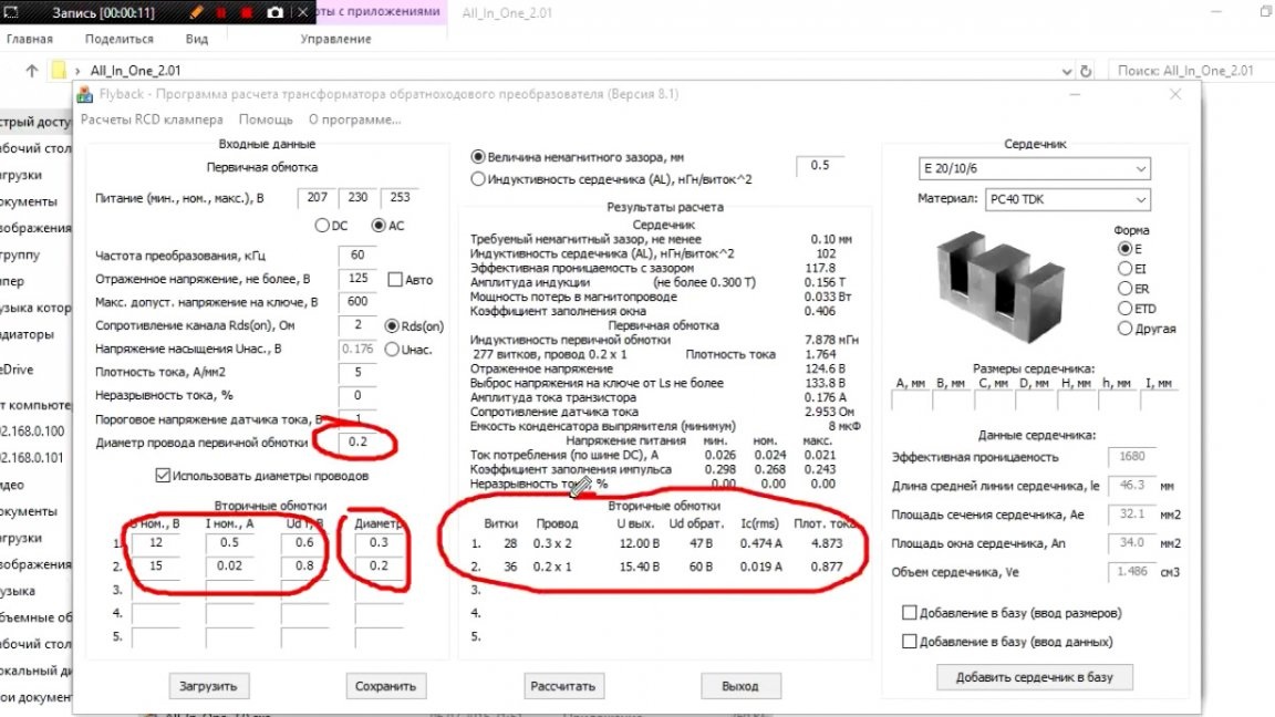
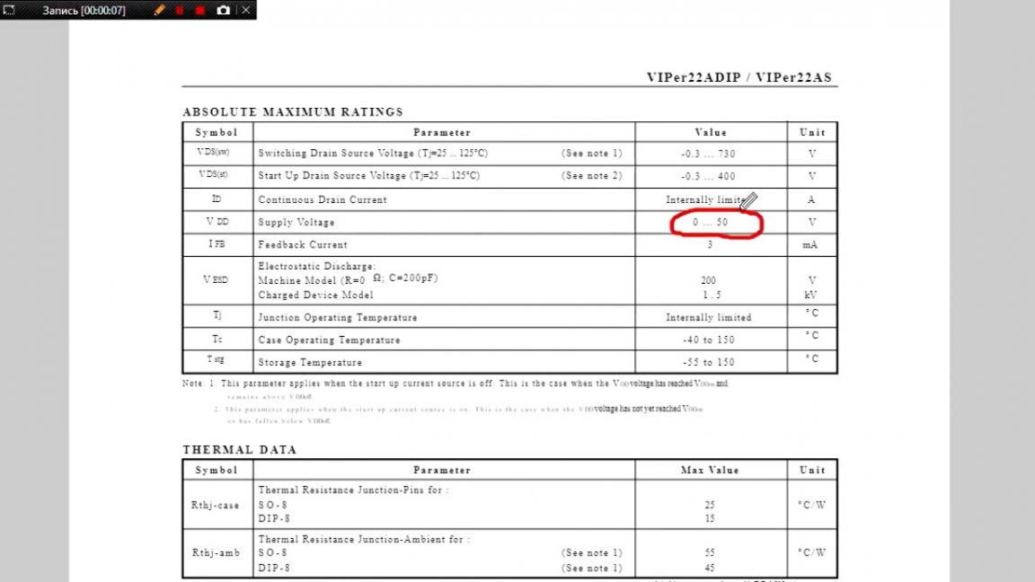
The author chose the self-winding winding at 15V, although it can be seen from the datasheet that the voltage can be raised up to 50V.
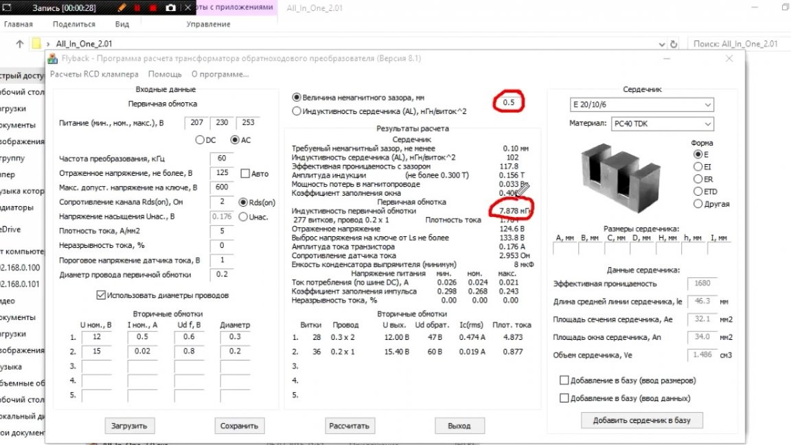
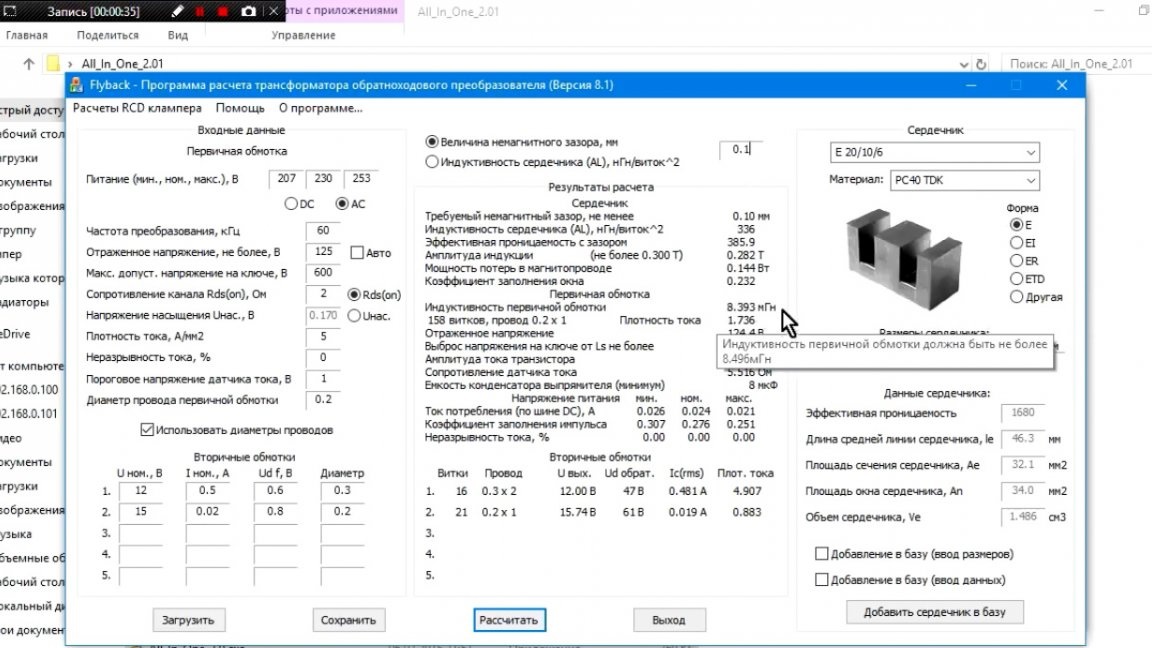
Also an important role is played by the gap in the core. As mentioned above, this is not a transformer, but a choke, and if you do not make a gap, you will get a large inductance that will not have time to give energy to the load and the choke will go into saturation, which is bad.
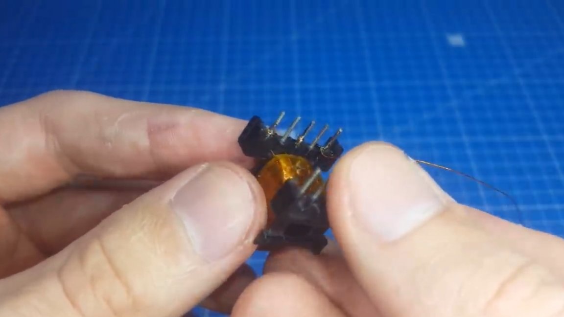
When we figured out the calculations, we turn to the winding. Now you will see how the author of this project shook his transformer. First of all, we take our frame, we fix the beginning of the primary winding and begin to wind.
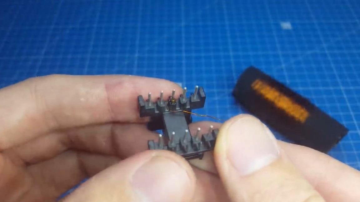
All windings are wound in one direction, let's say to the right, so we will not confuse with phasing. The start and end of the winding are indicated on the printed circuit board.
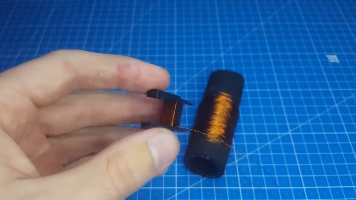
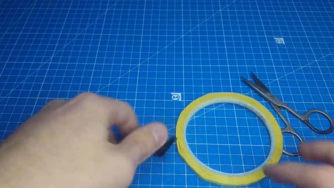
We try to wind the coil to the coil. After filling the layer, it is necessary to make insulation. For this we need a thermal tape.
We isolate the surface and continue to wind in the same direction and thus make so many layers to fit the primary.
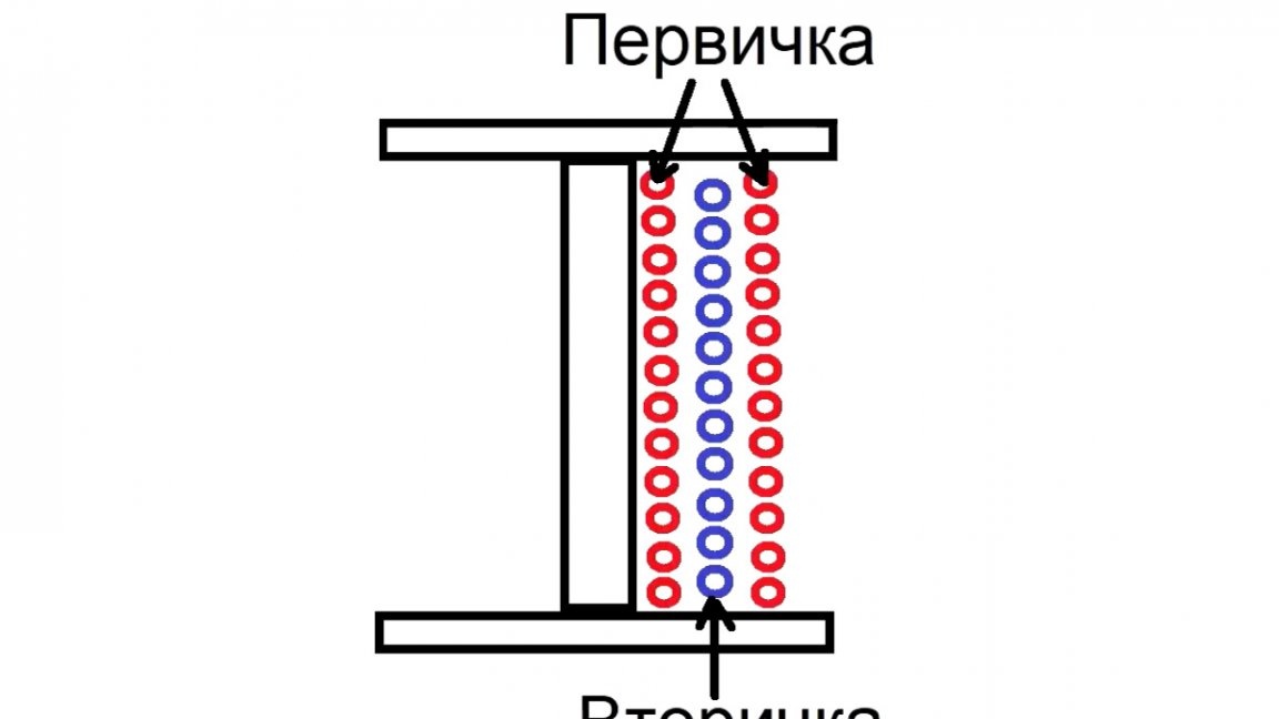
Insulation should be used in each layer to increase safety. It is worth saying right away that the winding technology is incorrect, but for such capacities it will, and in a more powerful version, the author promises to show the correct winding. It consists in dividing the primary into 2 parts, one part will be at the very bottom, and the second - at the top. Thus, flux linkage will be better.
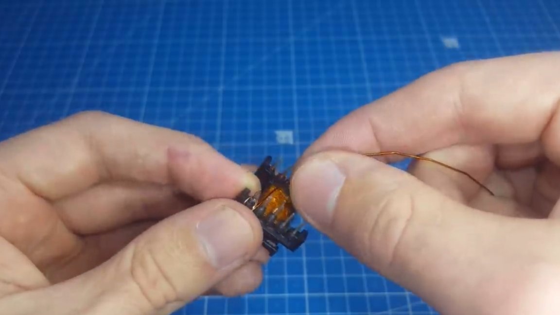
When they wound the primary, we start to wind the self-winding winding, everything is also to the right, observing phasing, there is nothing complicated.
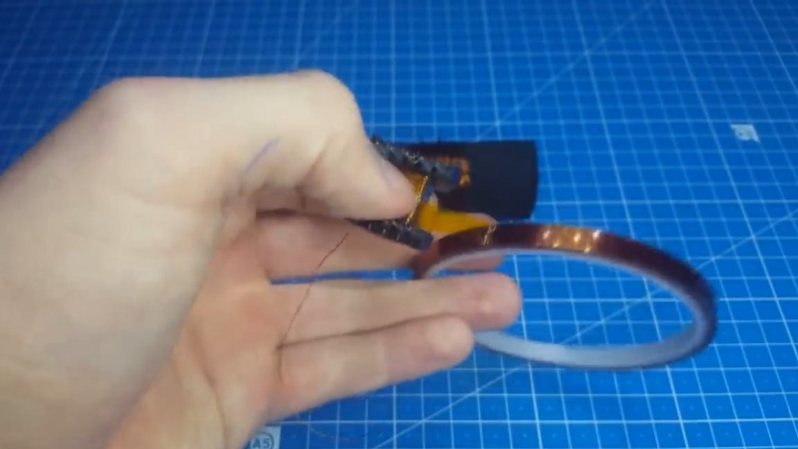
At the end, another layer of insulation and now proceed to winding the secondary. Its findings are located on another part of the frame, the direction of the winding is preserved.
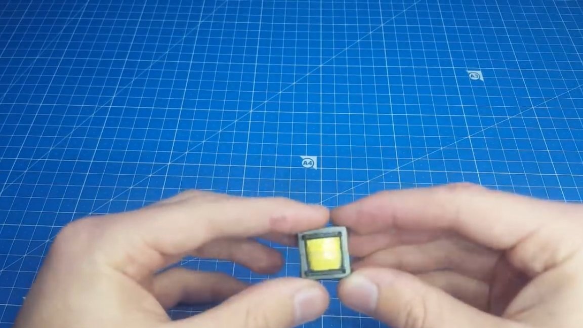
When finished and with the secondary, they made isolation with such a yellow ribbon for beauty.
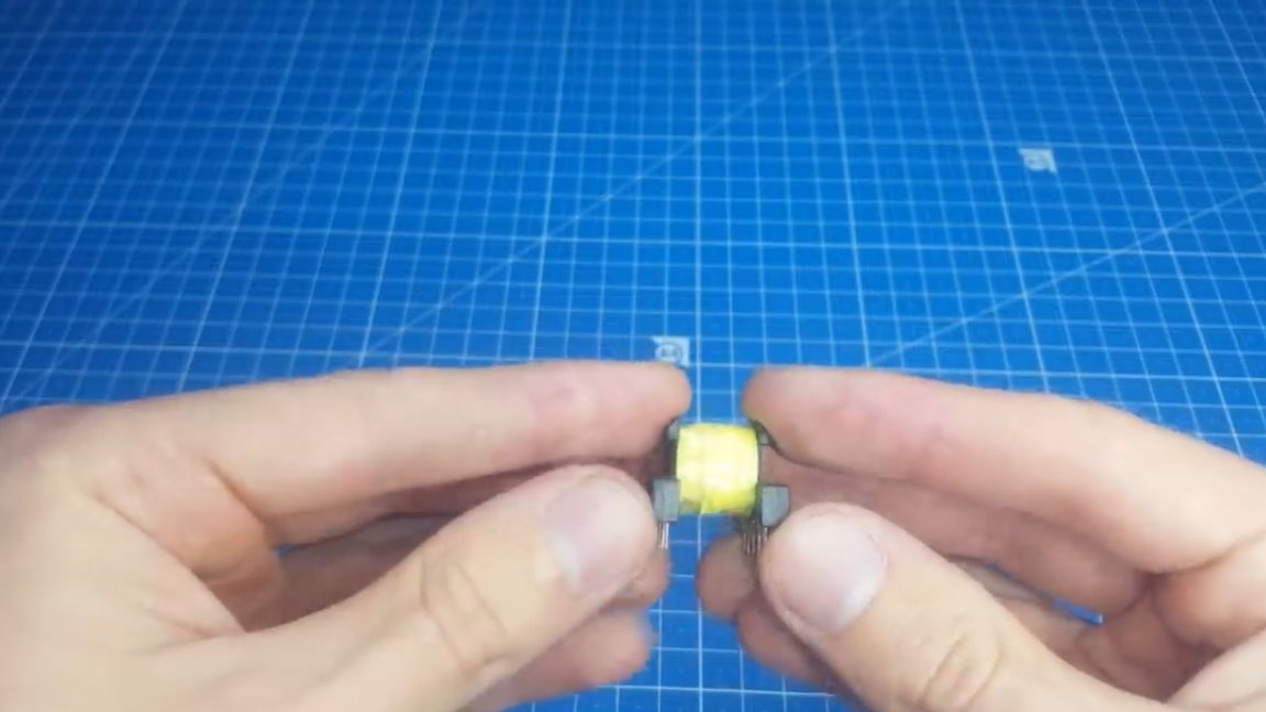
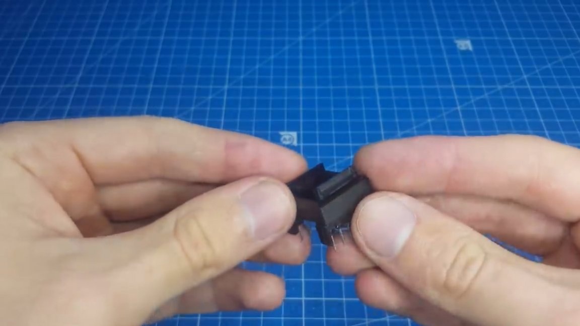
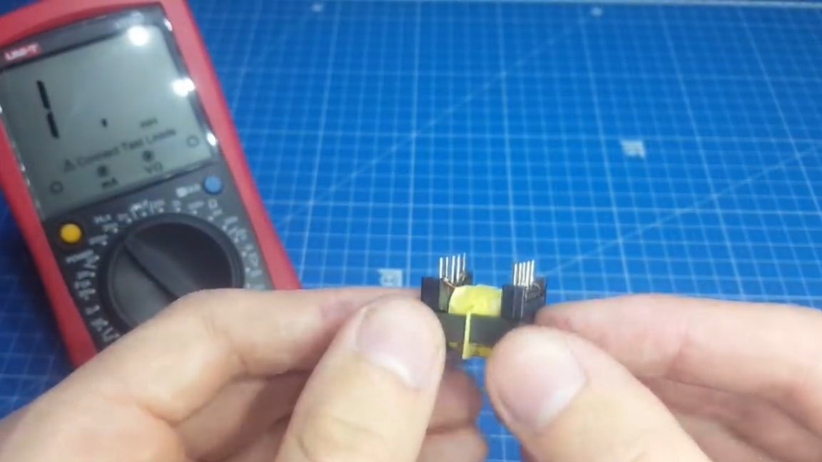
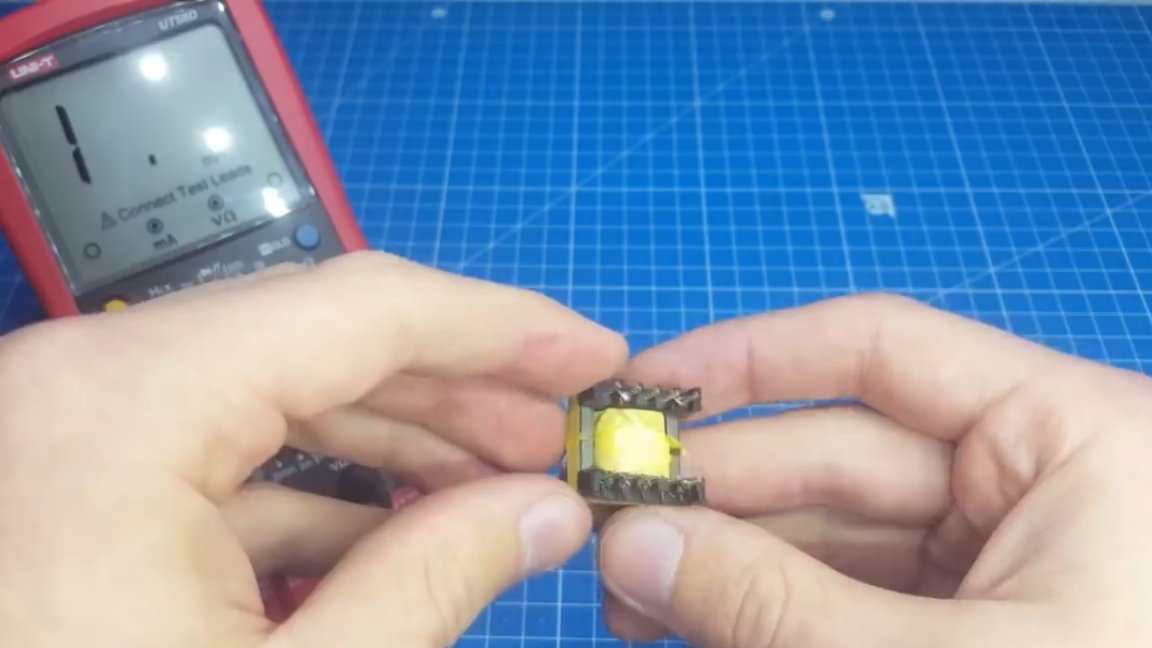
Next, you need to plant the halves of the core on the frame. If everything is wound correctly, then they should sit down freely.
Now that’s why the author doesn’t like the flyback so much - this is a gap. In principle, it will work even if you make an eye gap, but we want a quality block, so we begin to select a gap. In this case, the yellow ribbon went perfectly, its author took in 2 layers.
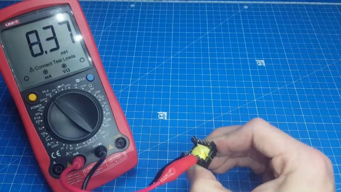
And now we check the inductance using the device.
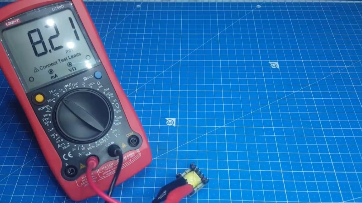
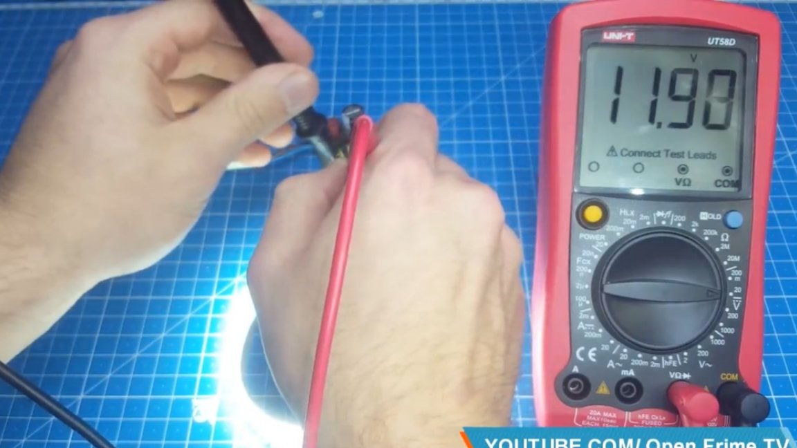
As you can see, it coincides with the calculated one, which means that they are wound well and the correct gap is selected. On this assembly is completed and traditionally we have tests. We connect the unit to the network and check the output voltage.
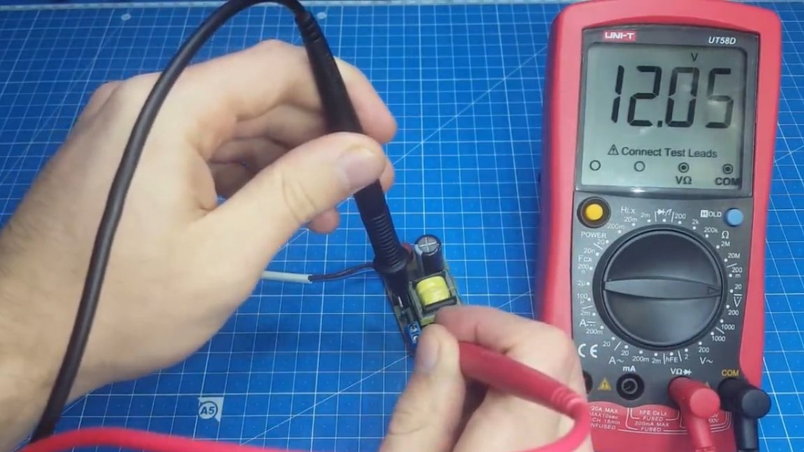
12 volts - everything is fine. Now we pick up a small incandescent bulb, designed for a voltage of 12V.
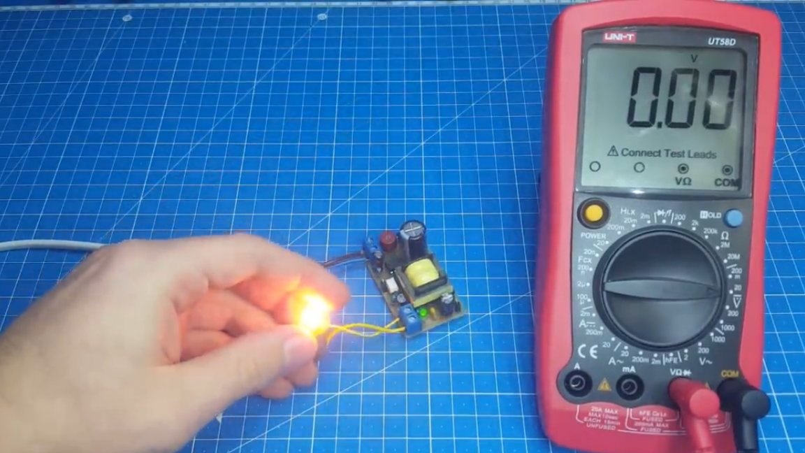
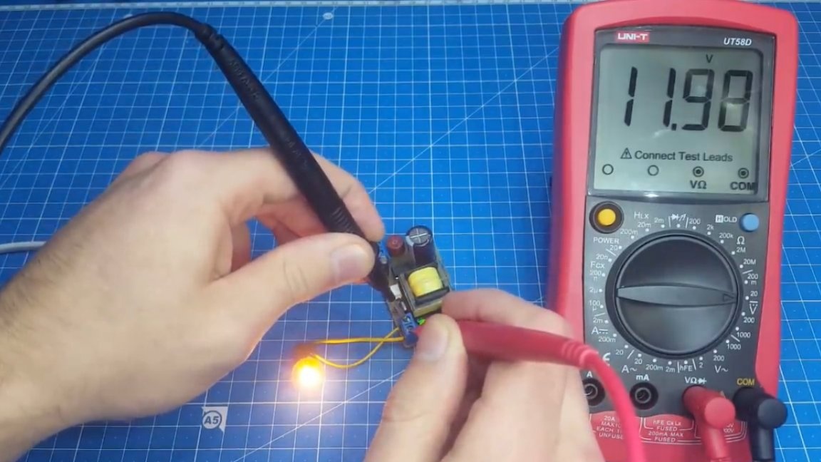
As you can see, everything is fine again. We can even pick up an LED strip in the load, the result is the same.
In general, you can safely recommend this unit for repetition. Thank you for attention. See you soon!
Video: