» Electronics » Power supplies »Uninterruptible battery charger with dimmer

Uninterruptible Battery Charger with Dimmer

Uninterruptible Battery Charger with Dimmer

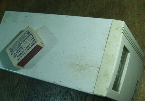
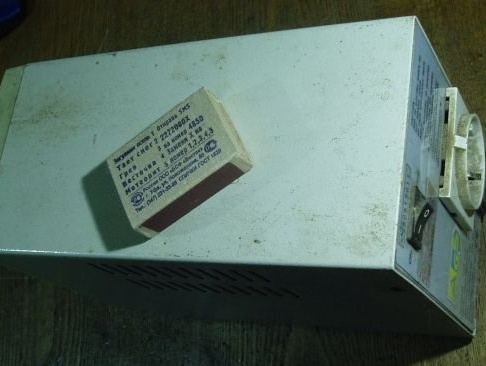
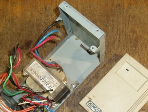
Once I got an old uninterruptible from a computer for parts. But I did not disassemble and dispose of it. I decided to make him a charger for car batteries, especially since the power of his transformer for this purpose was quite enough.


I made chargers from old uninterruptible power units several times, but it was completely ugly crafts whipped up, assembled on a plank, without adjustment and even without a fuse. The site even published one of them

Of course, somewhere in the forest, in the village 100 km from the city, a dead battery, if absolutely necessary, you can try to charge from anything, but for constant use you need a good and safe design.

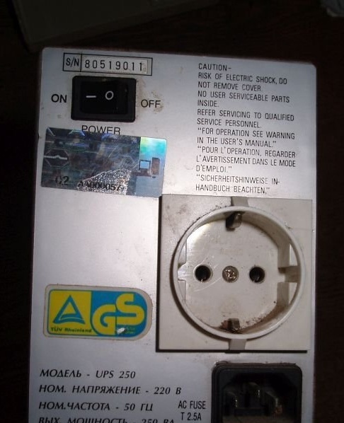
We disassemble the uninterruptible system and remove everything unnecessary. We leave the network connector with a fuse, an output socket (still useful), a transformer, a switch.


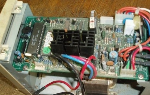
You will also need a powerful diode bridge with a radiator, a 4700 uF 35V capacitor, a cooler from a computer (but this is not necessary), a microammeter (I got from an old cassette), a shunt of about 0.3 Ohm and a dimmer. A dimmer is the most common, used to adjust the light in the rooms, at 300 watts.

First you need to check the transformer. We find in it the winding with the greatest resistance. This, most likely, was an output winding, with a voltage of 220V.


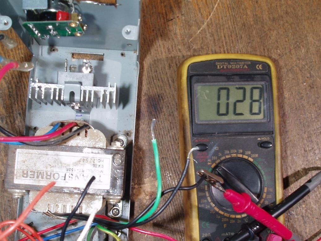
Now it will be the entrance. We apply voltage to it from the outlet and measure how much it will be at the output.


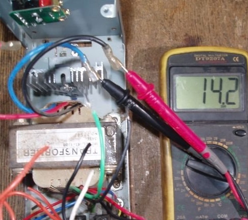
It turned out 14.2V. alternating current. After rectification on the filter capacitor, you get about 19V.

We are taking apart the dimer, we only need it electronic filling with regulator.


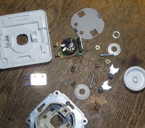
Well, then everything is simple. By corners and screws with nuts we fix all these spare parts in the housing and connect all the above spare parts.
It makes no sense to give a connection diagram, because there is nothing complicated in it.

The socket, which used to be an uninterruptible power outlet, is soldered directly to the network connector, and now simply acts as an extension cord.

The dimer is included in the gap of the network wire, in series with the network switch, and regulates the voltage at the input of the transformer.

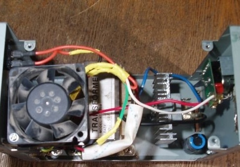
The transformer output is connected with its terminals to a diode bridge, on which there is a corresponding marking: ~, +, and -.
The filter capacitor is soldered directly to the terminals of the diode bridge, according to its polarity. The wires from the fan are soldered here, red plus, black minus. From the diode bridge, the blue “minus” wire goes directly to the “minus” of the battery.


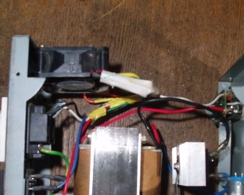
A positive brown wire from a diode motor is soldered to a shunt assembled from three parallel-connected ceramic resistors with a resistance of 1 (one) Ohm. The result is 0.33 ohms. Power resistors 5 watts. From the output of the shunt, the brown wire goes to the "plus" of the battery.


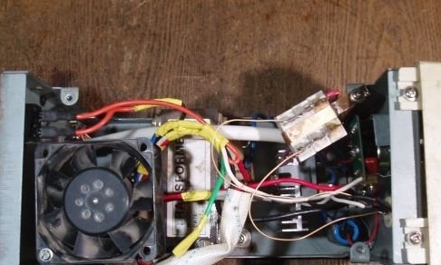
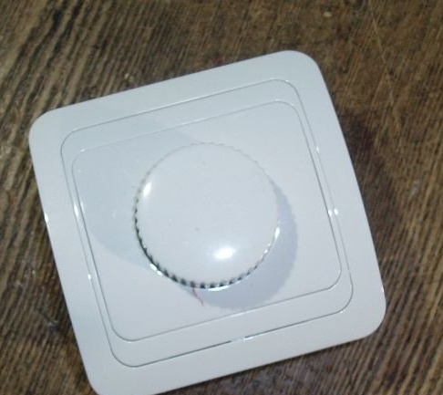
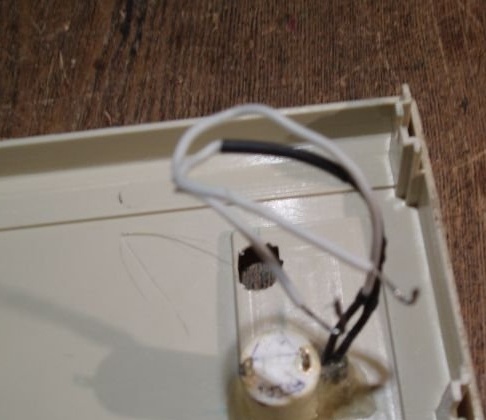
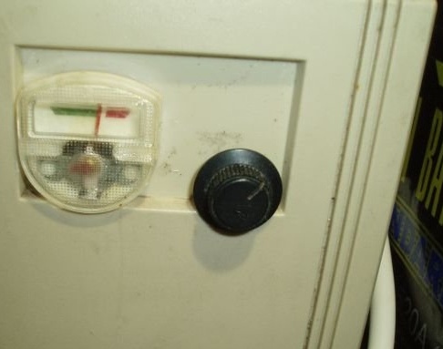
The microammeter wires are soldered directly to the terminals of the shunt. The microammeter itself is fixed to the plastic front panel using hot melt adhesive. The holes in the plastic panel for the microammeter and the dimmer knob are made with an ordinary knife. The regulator knob is fastened with the same hot glue.


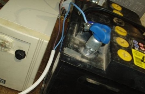
The battery is connected with special collet terminals purchased at the car shop on occasion.

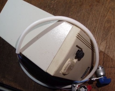
Before turning on the charger, connect the battery (strictly observing the polarity!), And turn on the device.

By adjusting the input voltage, the battery charge current is selected at the level of 5..5.5 A. This corresponds to the charging current of a 12-volt car battery for 55 ampere-hours. With the indicated shunt resistance (0.33 Ohms), the needle of the microammeter (current of its deviation according to the passport is 1 mA) will just be in the middle position of the scale.
6.9
6.8
6.7

Add a comment

    • smilesmilesxaxaokdontknowyahoonea
      bossscratchfoolyesyes-yesaggressivesecret
      sorrydancedance2dance3pardonhelpdrinks
      stopfriendsgoodgoodgoodwhistleswoontongue
      smokeclappingcraydeclarederisivedon-t_mentiondownload
      heatirefullaugh1mdameetingmoskingnegative
      not_ipopcornpunishreadscarescaressearch
      tauntthank_youthisto_clueumnikacuteagree
      badbeeeblack_eyeblum3blushboastboredom
      censoredpleasantrysecret2threatenvictoryyusun_bespectacled
      shokrespektlolprevedwelcomekrutoyya_za
      ya_dobryihelperne_huliganne_othodifludbanclose
25 comments
I'm not talking about charging! I - about to work long from him later))))
Specially found a brand of these diodes. These are TWO 204-35 and TWO 204-35X. With the letter X, reverse polarity diodes.
I specify the conductivity relative to the body. For some, the casing is the anode, and is marked in red; for others, it is the cathode, and is accordingly marked in black. Externally, they look exactly the same. The good thing is that you press two diodes into two radiators, and you get a bridge whose shoulders are the radiators and the tops of the diodes (where the variable will be and where the constant will depend on which pairs to press into the radiators).
The uninterruptible system uses the second method
Not sure, I stop charging the battery when the charge current drops below 20mA! smile
"break your brains" so that it does not turn off after a certain time and does not squeak
Chose from 4 different models. I just plug the power cable into a power outlet, without pressing "POWER" button, the click of the relay is heard and charging started! No squeaks and blackouts, honestly charges in the off state! smile
There are two ways to charge the battery without harming the battery:
1. U = const
2. I = const
It is interesting to what type this (and similar) memory can be attributed, provided that the person does not constantly stand and wind the current adjustment knob? As the battery charges and its internal resistance increases, the charge current will decrease, and the voltage will increase accordingly! smile
Damn ... And I thought that they are all the same and you can just turn them over .... smiles
It looks like the charge circuit there with a claim to "intelligence", pulled out the battery with almost zero voltage at the terminals. The UPS builds up the terminal voltage gradually as the battery charges. smile

There are two ways to charge the battery without harming the battery:
1. U = const
2. I = const

In the uninterruptible system, the second method is used. The primitive brains of the device follow this after all ... And the tension "dances" when the internal resistance changes due to the gnarly law of Grandfather Zhora. (He is also Syoma)))))
I wrote that this is due to the performance features. In traction, for example, in which the plates are massive, this figure is much higher.
Also used an uninterruptible at a construction site without electricity with an external, car battery. The operating mode is "an hour or two of work - a couple of days of charging" ... I measured the charge - I was normally charged, there were enough springs. !!! The only thing was that he had to somehow “break his brains” so that he wouldn’t shut off after a certain time and did not squeak.))) (I don’t remember exactly, it was a long time ago. But, it seems, the continuous mode set somehow through the USB connection, and the buzzer stupidly broke)))))
Quote: Khatul Madan
rectifier assembled from direct and reverse polarity diodes
scratch
0.5 Amperes possible ... and a couple of months, really
But it does not boil! 0.5A * 7days * 24 hours = 84Ah! To school, learn arithmetic! smile
The scheme that is commonly used in them for CHARGING (a not for charge) batteries
That’s how I used to solve the problem of eating at home, when there is a power outage
It turns out for a charge too?
does not give out more than 2 amperes
2A * 36 hours = 72Ah. He took measurements, it looks like the charge circuit there claims to be "smart", he pulled out a battery with almost zero voltage at the terminals. The UPS builds up the terminal voltage gradually as the battery charges. smile
Well, then I got something dead. In this uninterruptible power supply, I changed the burned-out output transistors; he used to power the TV in my country house from the old 72nd in the event of a blackout. So when charging, he did not give more than 13.0-13.2 even at “idle”, maybe there was something else covered, he didn’t find out, he just switched to charging from another uninterruptible power supply unit (SKAT 12/12), for a long time, it normally charged. And now I just bought a generator.
Quote: Valery
It must be limited to 10% of capacity.

This is so that at a high charge current there is no warping of the plates and their shedding.
the voltage there is only 13.0 or 13.2 (I don’t remember exactly)
Especially just - what I measured, the voltage at the terminals of the currently charged UPS 14.24 V battery!
For a car battery, you need at least 5 Amps.

MISTAKE !!! It’s possible and 0.5 amperes ... and a couple of months, really ... Well, all the same ...)))
The battery charge current depends on its internal resistance and, indeed, "the more it is planted, the more the current draws" ... It must be limited to 10% of capacity. (Due to performance features). But there is NO bottom line !!! If the voltage of the charger is higher than the voltage of the battery, then the current will "fill in" there.)))). And the only question is how long it will take to "saturate" it ...
I have a “charger” with a maximum current of 1.5 Amperes for "severe cases" (a collapse in a "deep discharge"). After I succeed in "waking up" the boned battery, I remove it from the main one (so as not to occupy it) and rearrange it. Because "the patient can only be fed with a teaspoon)))). And the stamper too (!!!!). They stand for weeks until the current drops (read: it has not been fully charged).
does not give out more than 2 amperes.
The fact is that he doesn’t give away these 2 amperes either because the voltage there is only 13.0 or 13.2 (I don’t remember exactly) and it is clearly not enough to fully charge 14.4 V. And it’s quite possible to charge the battery with two Amps, longer, but can.
Almost the same ten years ago I gathered it in haste, it still works.The transformer is a rewound ТС-180-2 rectifier assembled from diodes of direct and reverse polarity from some generator (I don’t remember the brand, I know that there is a direct current 40A), I didn’t set the output at the output, in my opinion this is an excess in the charger, the dimmer is also not I remember which company, but most likely the statement of our astronaut from the movie "Armageddon" "... everything is done in Taiwan ..." is fair. I charged them both the 55th from a dozen and the 72nd from Ford, yes, it buzzes (bias is possible due to the asymmetry of the triac), no, it does not heat up, no, it does not create interference to the network. It seems that the transformer has so much power that it allows him to ignore harmonics and bias like a rhinoceros, which is nearsighted from birth, but with its dimensions and weight this is not his problem.
In general, the design is quite functional, it is assembled quickly from almost ready-made blocks, almost everything can be found "for free", well, the ability to adjust the charging current is also not an unimportant moment, many modern memory devices do not have this.
So the war is 5 years old
Author
Hello. I have been repairing for a long time and I know the circuitry of uninterruptible power supplies. He will not pull an external battery, especially from a car. The circuit, which is usually used in them for CHARGING (and not for charging) batteries, in the most common models does not produce more than 2 amperes. The batteries in them are gel, either 7 or 12 amperes / hours. And for such a battery, this charge current will be almost nominal. Sometimes you come across models with two batteries connected in series. In these uninterruptible power supply units, the charge is simply higher, and the current is the same. For a car battery, you need at least 5 Amps. And when you connect a "planted" battery, the current will be more, up to 10 Amps. Of course, if you find an uninterruptible power supply for one and a half or two kilowatts, then you can attach an external battery to it. That’s how I used to solve the problem of powering my house when I turned off the electricity. But then my son gave me a gas generator and it became much easier.
Author
Hello, Ivan. More than once, I made chargers like this, with adjustment and protection at the output. On transistors, and even on thyristors. He also made the simplest ones, without adjustments, without protection, and even without a case. Here, bgm.imdmyself.com there is such a publication. Link in the article. Well, I do not want to fence a circuit, a board, a powerful transistor, another radiator, and so on and so forth. With a dimmer, everything is much simpler - included it in the gap of the power cord - and adjust. Specially, I did not test it, I just took it with a suitable power margin.
The transformer reacted to the dimmer with complete indifference. I myself thought that he would not like the output pulses from the thyristor regulator. And he does not even buzz. I did not connect the oscilloscope, but apparently the harmonics that are present there fall into the permissible frequency range of its core. The reference diode bridge has a maximum frequency of up to 1000 Hz.
What for there a dimmer. I have a regular car battery thrown to the uninterruptible. Plows for 5-6 years. No more - how much war - so much plows. = (
Interestingly, and if without alterations, just instead of a regular battery, connect an external one? Well, let it charge longer, with lower currents, for a battery it is more useful!
How did the transformer react to the additional harmonics in the input signal? Have the dimmer been checked for symmetrical response?
By the way, why did not you adjust the current in the secondary circuit, as, for example, in the ZU-2M?

We advise you to read:

Hand it for the smartphone ...