

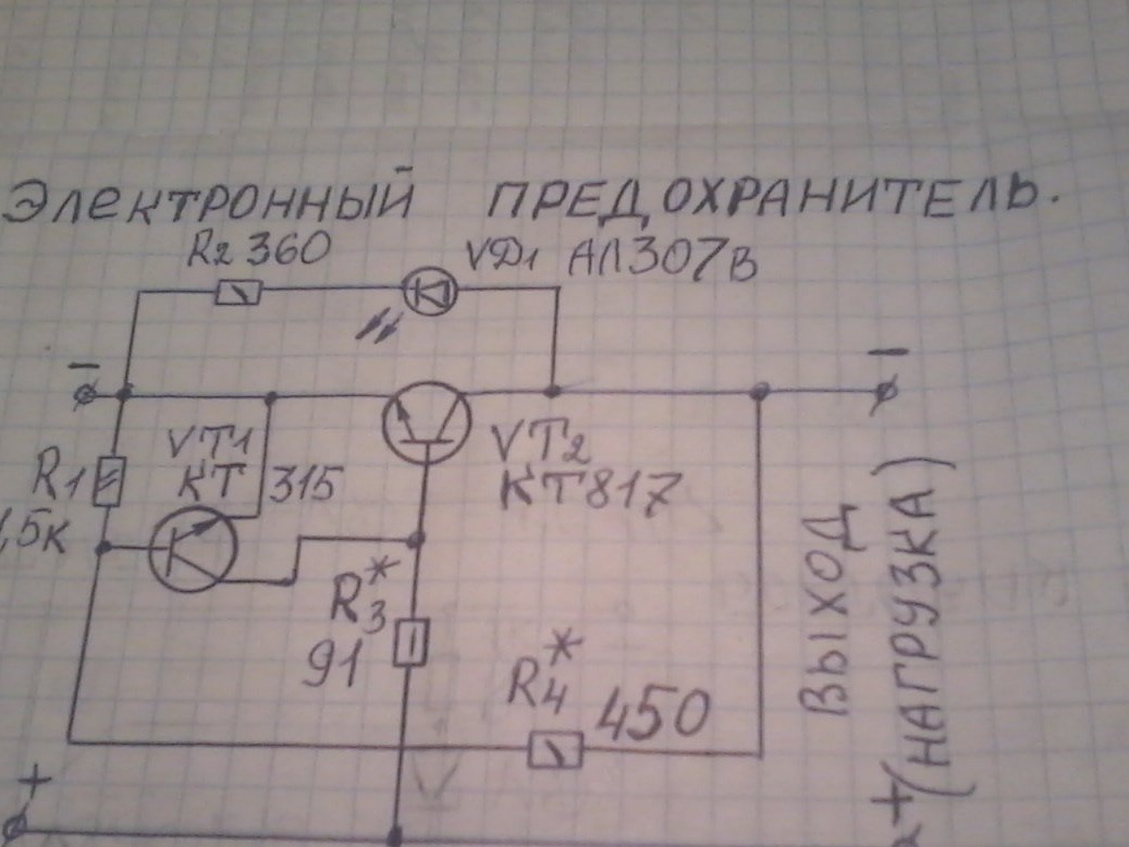
Hello, friends the inhabitants of our site! Many of you probably have a power supply for connecting to various electronic devices. But not all units are protected against overload and short circuit. I offer you a homemade product that will protect your unit from these troubles. Here is a diagram electronic fuse
I found her on the Internet. A little about the operation of this fuse. The device is designed for contactless emergency power off from the electronic device at currents exceeding a certain value. For these purposes, fuses are usually installed, but their speed is such that first all the electronics burn out and only then the fuse blows. The electronic fuse disconnects the load much faster and the likelihood of damage from overvoltage, or an unexpected increase in current consumption is sharply reduced.
The main element of the circuit is the transistor VT2, which is open in the normal state and the voltage drop across it is minimal. LED VD1 off. With increasing current consumption, the voltage drop across the transistor increases, and VT1 starts to open. As a result of this process, transistor VT1 quickly opens, and VT2 closes, and disconnects the load from the power source. In this case, the overload indicator LED VD1 lights up. When a short circuit is eliminated, or the load is disconnected from the electronic fuse, the device is restored to operability.
A fuse is connected between the output of the power supply and the load. All this is shown in the diagram. To assemble this device, we need the following parts and tools
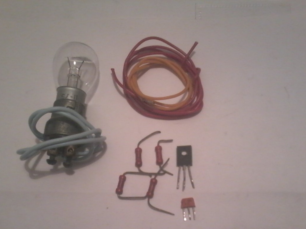
1 - mounting or printed circuit board of a small size, for example, 5 by 5 cm; transistor KT817; transistor KT315; LED AL 307v, preferably red; MLT resistors 0.25 W 360 ohms; 0.125 W 1.5 com; 0.5 watts 91 ohms; 0.25 watts 450 ohms; mounting wires. 2 - soldering iron; solder; tweezers; nippers; pliers; multimeter; Automotive lamp 12 V to 21 W - to connect it instead of the load. We assemble as follows.
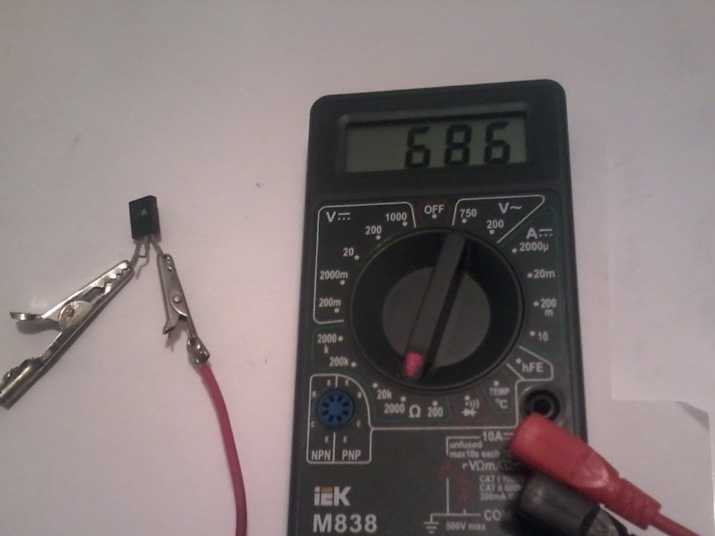
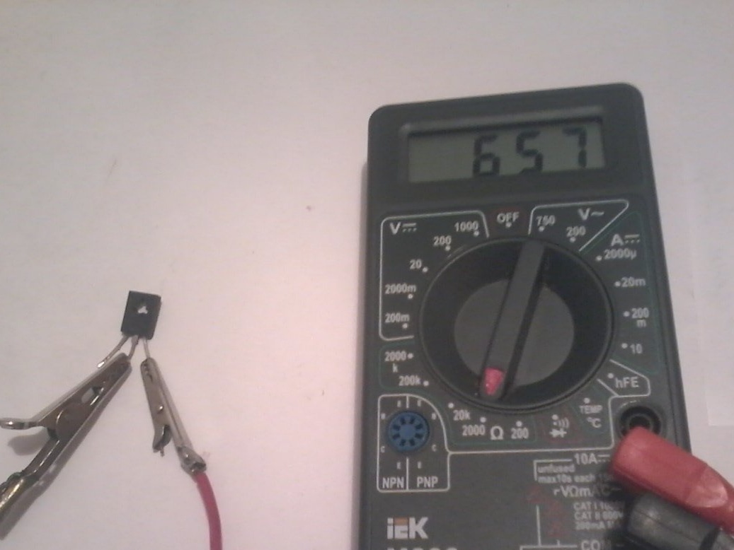
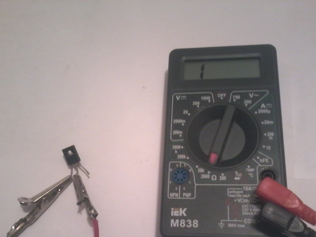
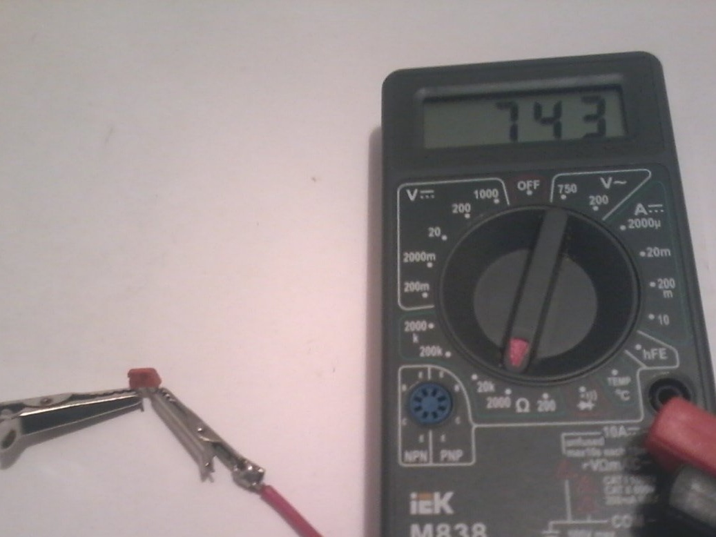
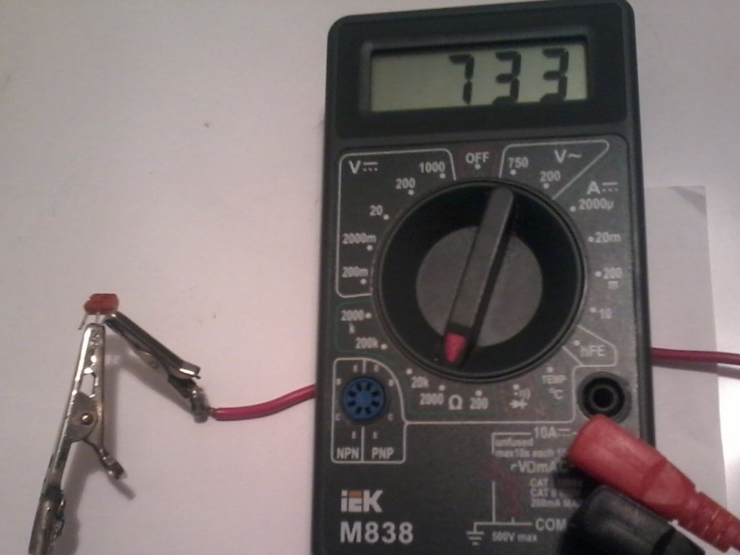
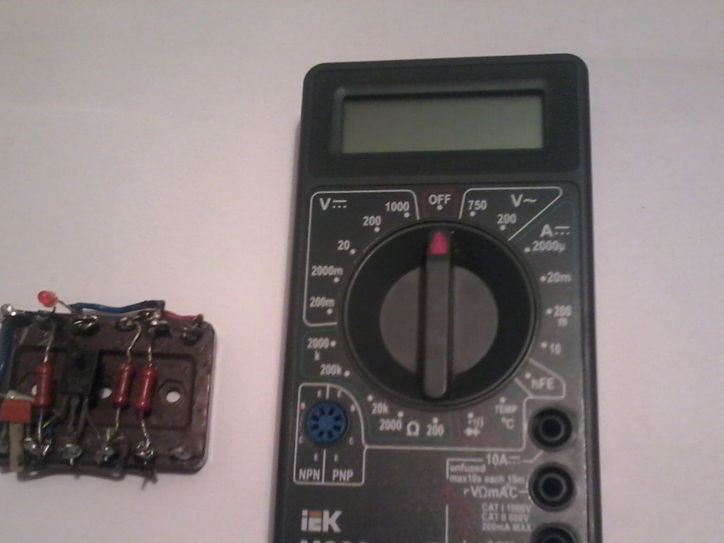
Step 1.We check all the details with a multimeter, since among them there are B / U
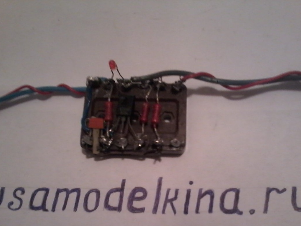
Step 2. We solder the whole circuit on the circuit board. Checking the correct assembly of the circuit
Step 3. Connect the assembled device to the output of the power supply according to the diagram, and connect the load to the output of the fuse, for example, a car lamp 12 to 21 watts. At the indicated ratings, the device operates at a current of 1A and a supply voltage of 9V.
To change the characteristics of the fuse, the values of the resistors R3 and R4 will have to be converted according to the formulas below.
R3 = Uin * Vst / In. max
where Uin is the input voltage in volts; B is the static current transfer coefficient of the transistor VT2; I n.max - maximum load current in amperes.
R4 at currents up to 1.5 A is calculated from the condition: R4 = 0.05 * Uin (com). At currents of 1.5A --- 10A, R4 = 0.02 * Uin. (Com).
Step 4 Check the operation of the electronic fuse. To do this, we connect a car lamp 12 to 21 W with a consumption current of more than 1-1.5 A to the fuse output. Since the fuse is designed to operate at a current of 1A, the lamp immediately goes out and the overload indicator LED VD1 lights up. In this state, the fuse will remain as long as desired until the load (lamp) from its output is disconnected. After disconnecting the load, the operation of the device is restored automatically. This suggests that the circuit is working. With a minimum of parts, the fuse works quite well - not bad, and the lamp is intact, and the power supply has not blown.
That seems to be all.
I wish you all good luck in creating your own homemade products.