

Hello dear friends the inhabitants of our site and site visitors!
Many of you have tested zener diodes. Not all of them can be checked with a multimeter and the stabilization voltage of the zener diode can be determined if the inscription is erased on it. I bring to your attention a simple circuit that will help identify and check the zener diodes. Here is the prefix diagram
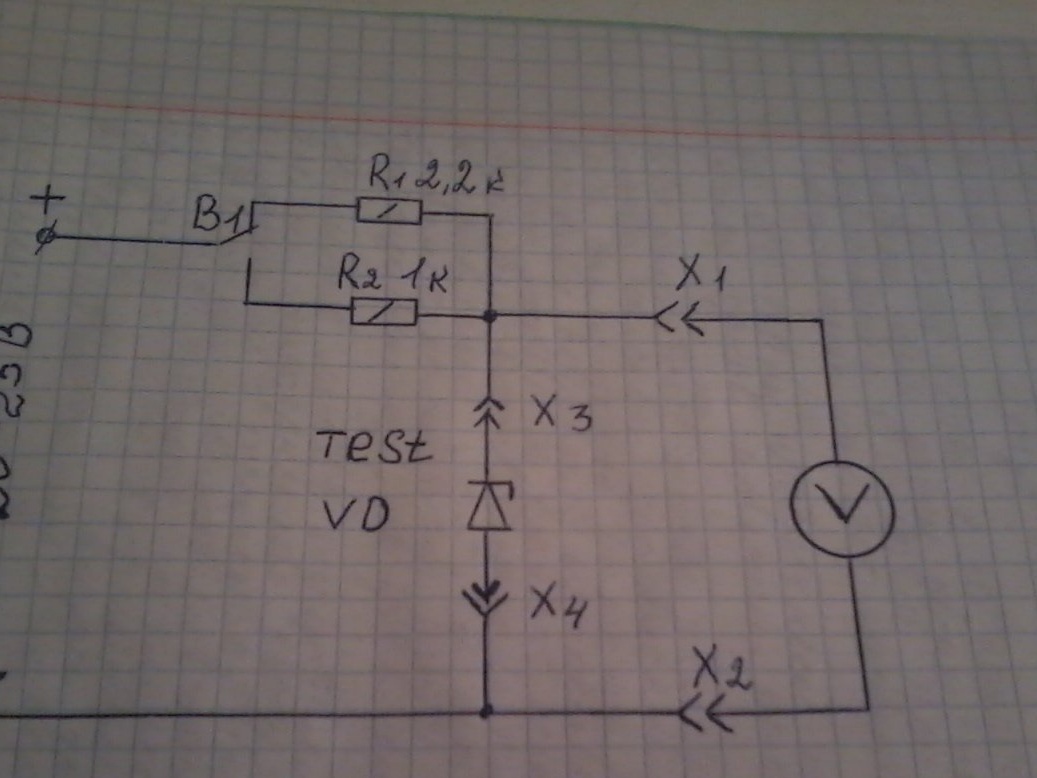
I took her from the internet. The proposed circuit serves to easily determine the nominal voltage of the stabilization of the zener diode using a voltmeter, as well as to determine its serviceability.
Now industry produces a large number of different electronic components and often when assembling a radio electronic product, there are many difficulties in determining the nominal value of a component. Domestic industry was particularly distinguished in this regard - in particular, zener diodes in a glass case sometimes have very similar markings, which cannot be distinguished. For example, these are Zener diodes KS 211 and KS 175 - sometimes there are marking options in which both look like a small output glass diode with a black strip. One way or another, remembering the color marking of the zener diodes is not the best idea, considering how simple they can be checked.
To assemble this device, we need the following parts and tools
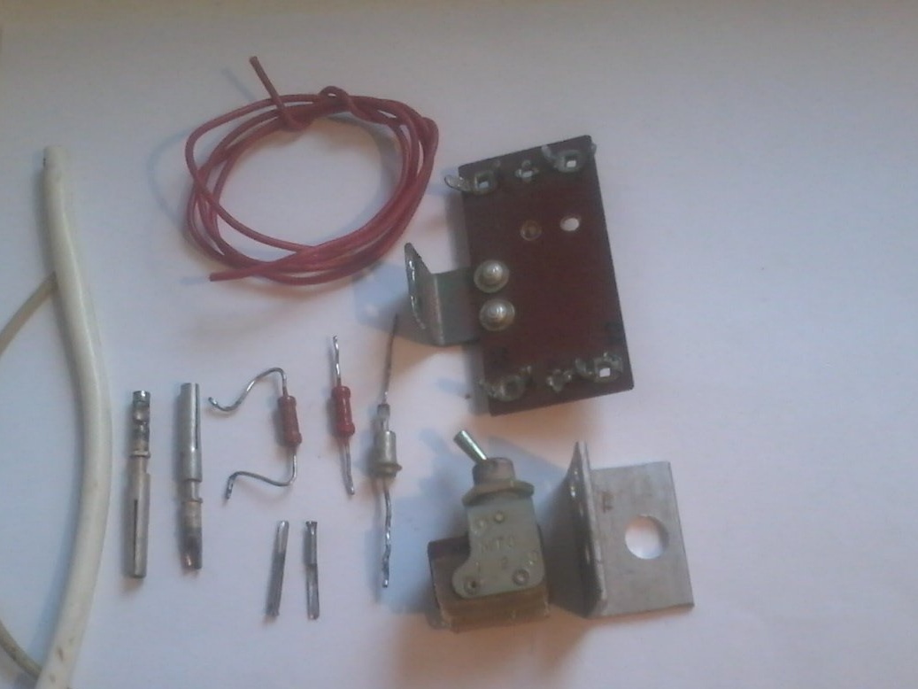
1 - a small mounting plate measuring 5 by 2.5 cm; micro switch MT - 3; aluminum corner, measuring 2 by 2 cm and 3 cm long; MLT resistor - 0.25 watt 1 com and 2.2 com; two “Mom” sockets from a military plug for connecting a multimeter; and two of the same connectors, only smaller - for connecting zener diodes; cambric; mounting wires.
2 - soldering iron; solder; tweezers; nippers; pliers; drill and drill.
We assemble as follows
Step 1
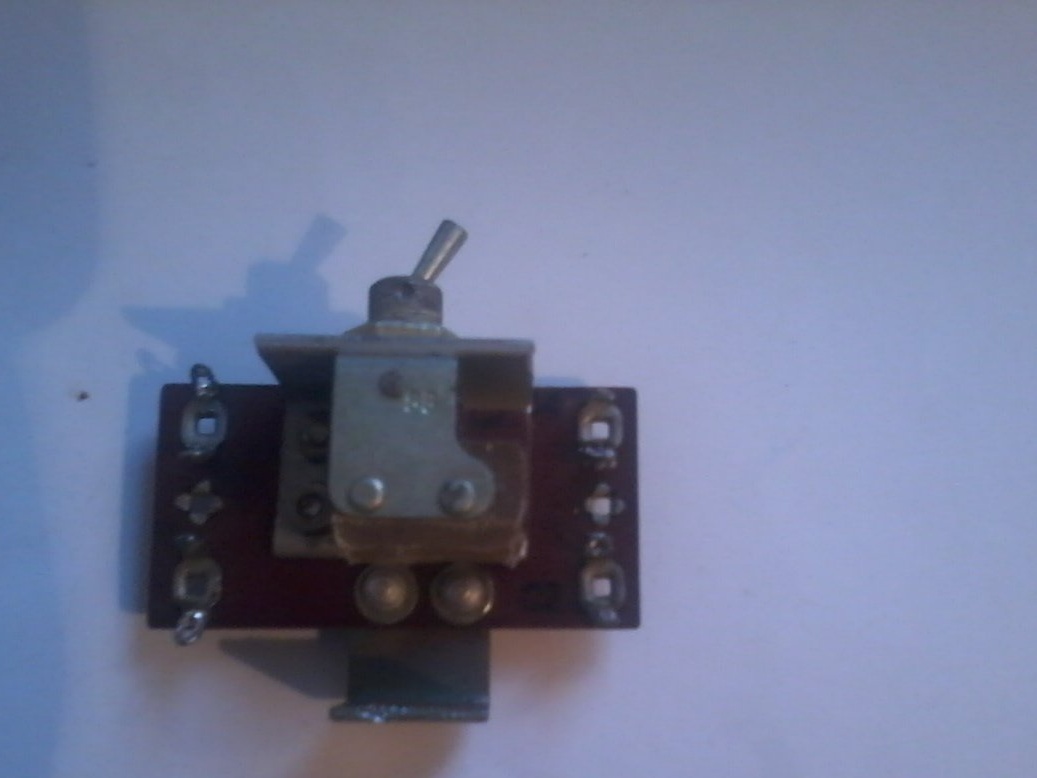
I fix the toggle switch on the corner, and install it on the board.
Step 2
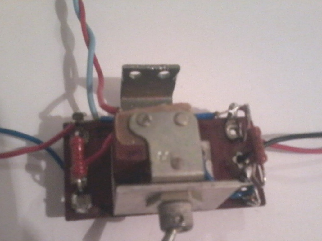
I solder the whole scheme. I check the correct assembly. Typically, the operating current range of low-power zener diodes is in the range of 1-10 mA, so the resistance of the resistor R1 selected 2.2 kom. This is optimal for testing low-power zener diodes. To test powerful zener diodes, the resistance will have to be reduced, and for this, switch B1 is installed.
Step 3. Check the operation of the assembled device
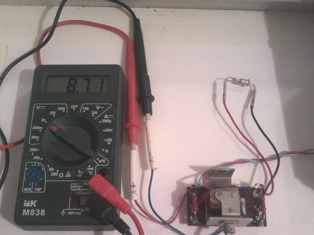
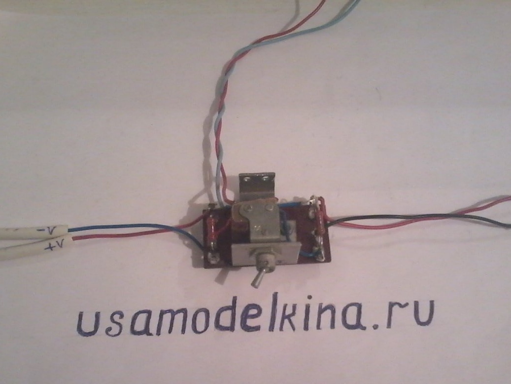
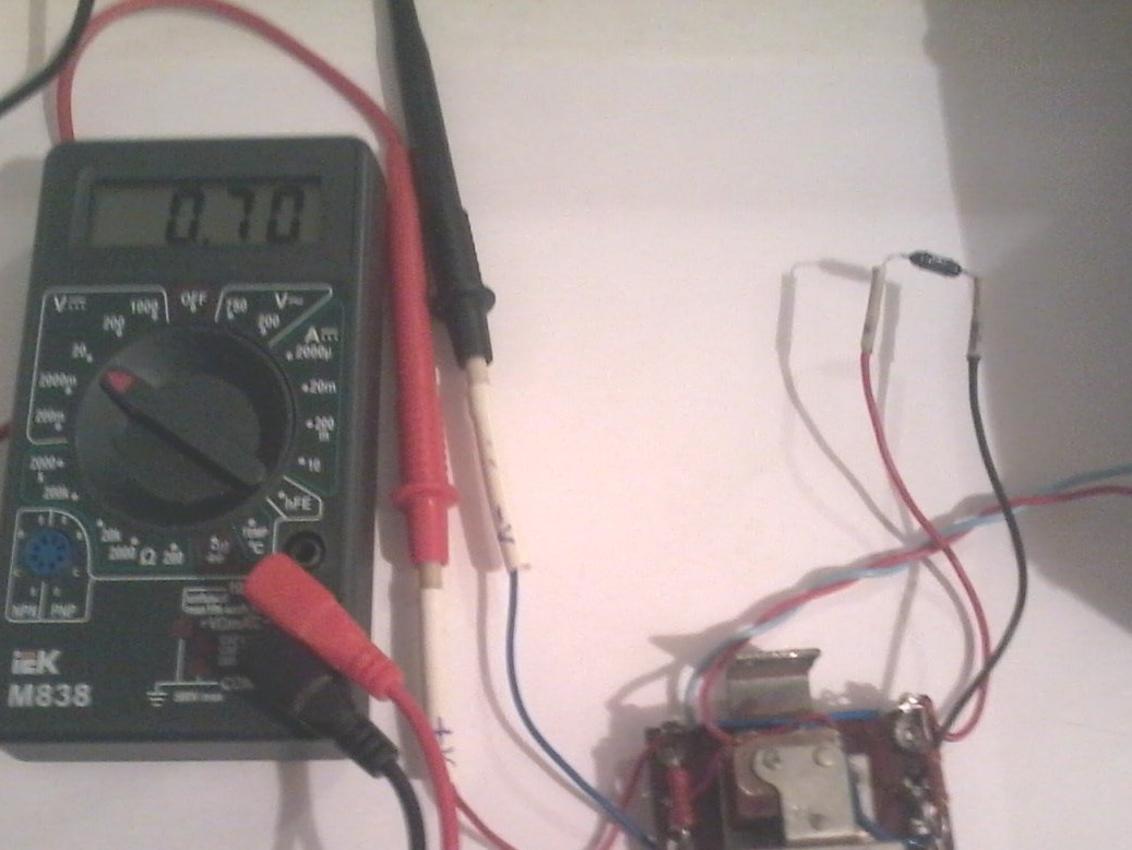
To do this, connect the multimeter to the X1 and X2 connectors in the DC voltage measurement mode. We connect the tested zener diode to connector X3 and X4, as shown in the diagram.We supply 20 V power to the circuit, if the zener diode is connected correctly, then the voltmeter will show its stabilization voltage, and if it is wrong, some very small voltage near zero
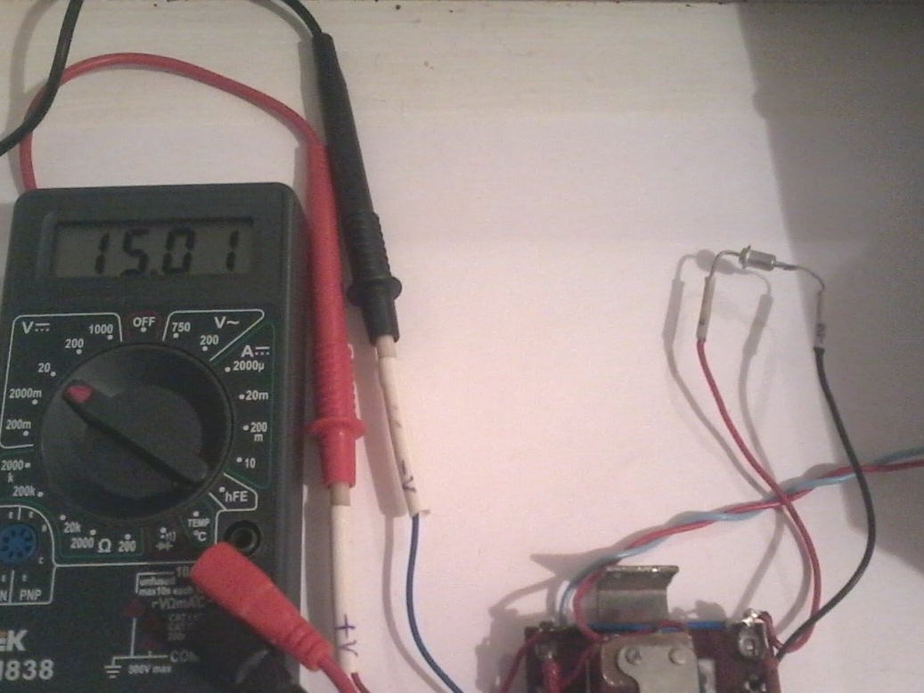
If with one connection the multimeter shows the minimum voltage, and with another - the maximum equal to the voltage of the power source, then the tested radio element is either a simple diode or a zener diode with a stabilization voltage higher than the voltage of the power source.
If you are sure that this is a zener diode, you need to increase the voltage of the source to the expected value and check again.
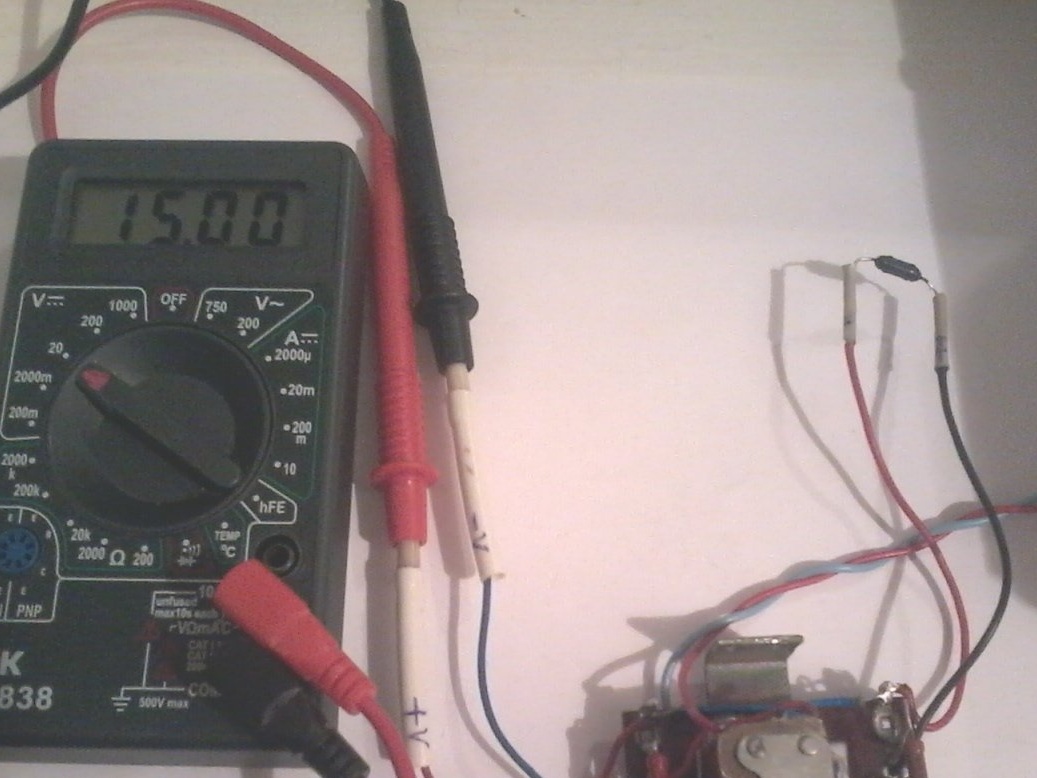
If the voltmeter shows the minimum voltage or the supply voltage at any connection, then this zener diode or diode is faulty.
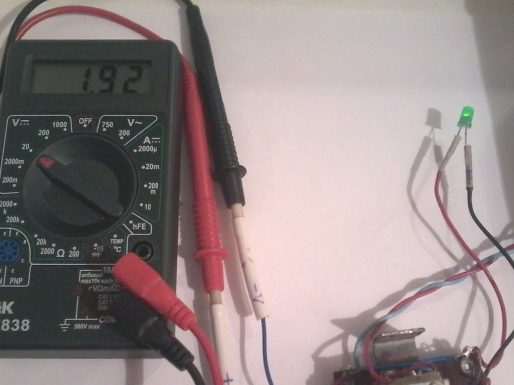
If the stabilization voltage is shown with any connection, then this is a two-sided zener diode. In this way, you can check the health of diodes and LEDs, only the polarity will be the opposite. The method is good in that it allows you to know the voltage drop, which is very important. When checking the LEDs, it is necessary to reduce the voltage of the power source to 9V.
All methods for checking the zener diode, diode and LED are shown in the photo
With the simplicity of the circuit, a quick check of the indicated radio components is achieved.
That's all, I wish you all success in creating your own homemade products.