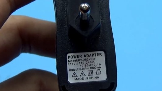
Today, we, together with the author of the YouTube channel “AKA KASYAN”, will be engaged in increasing the power supply. As an experimental, we have a cheap charger for phones.
On it, the author will demonstrate the principle of rework, and you can use the same principle to rework other power supplies. The Chinese manufacturer claims that our power supply is five-volt and produces a current of up to 1A at the output, but now, let's check it.
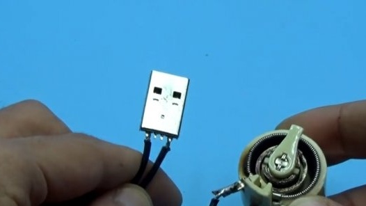
As a meter, we have a high-precision usb tester. The load is a variable wire resistor or rheostat.
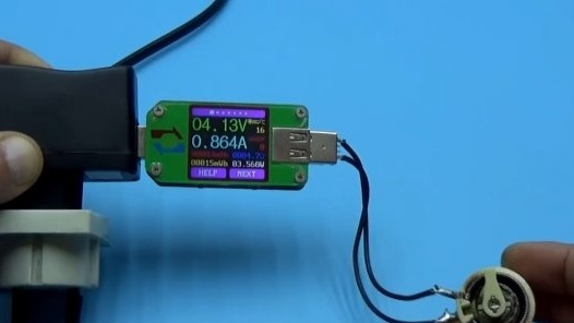
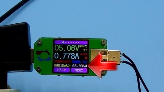
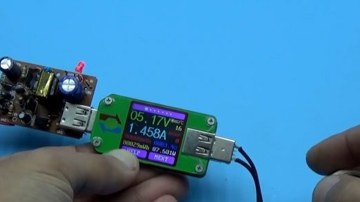
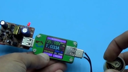
We turn on the tester to the charger and see that the voltage is really within 5V.
Well, it's time to load this miracle.
Here we clearly see that with an output current of more than 800 mA, the output voltage drops below 5V, and with a current of 850 mA the drawdown is very hard - this is the limit. If you ship more, protection will work. Based on this, we can say that the parameters declared by the manufacturer are overestimated, but even with a current of 800 mA such a unit will not last long. 400-500 mA output currents are more or less safe for him, this is enough for ordinary dialers, but not for smartphones.
As a result, using the data obtained, we can say that the power supply is within 4 watts. Remember this number and analyze the block.
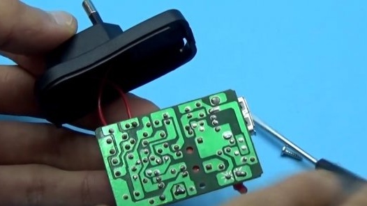
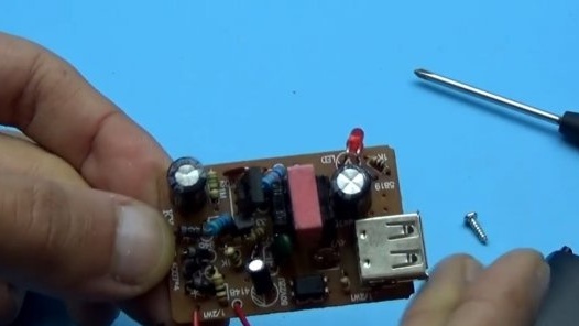
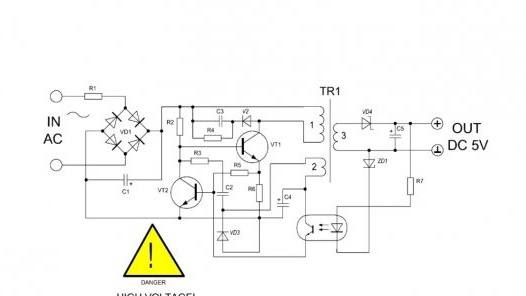
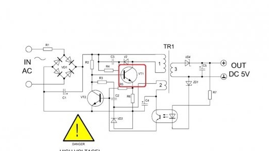
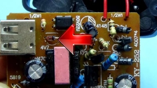
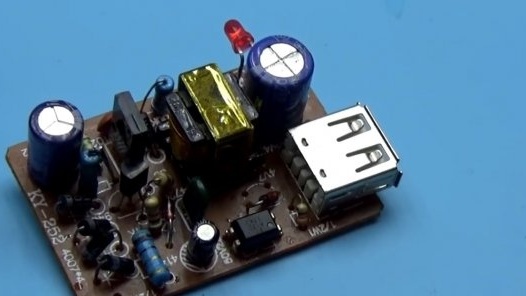
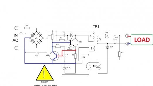
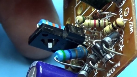
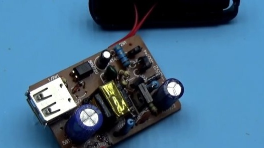
Everything is budgetary inside, the quality of the board itself is not so hot. It was built according to a rather popular topology - a self-generating switching power supply with current protection and stabilization of the output voltage.
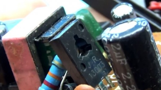
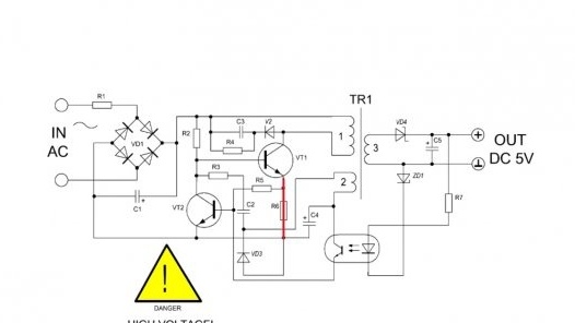
The block is built on only one transistor, as a rule, this is a high-voltage bipolar transistor.
There is another transistor in the circuit, a protection system is built on it, but more on that later.
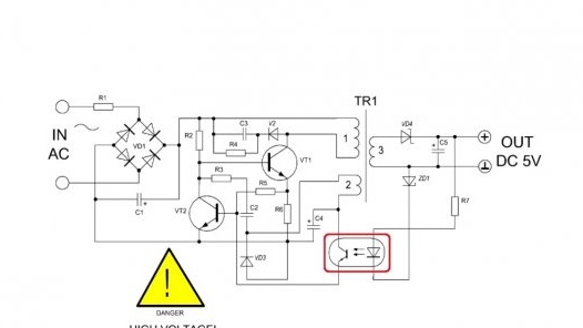
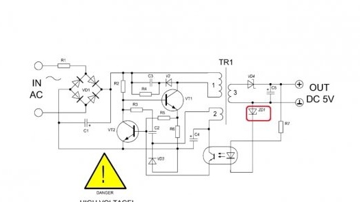
Feedback or voltage stabilization is based on an optocoupler and an ordinary zener diode.
In general, if you look carefully, the board provides a seat for installing a voltage reference source, but the manufacturer decided to save money and installed a regular zener diode.
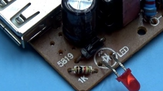
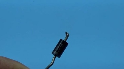
But if everything is done correctly, then such a simple circuit on a single transistor will work very well for many years. Now for the rework. First, we throw out the output rectifier (here there is a single-ampere Schottky diode 1n5819).
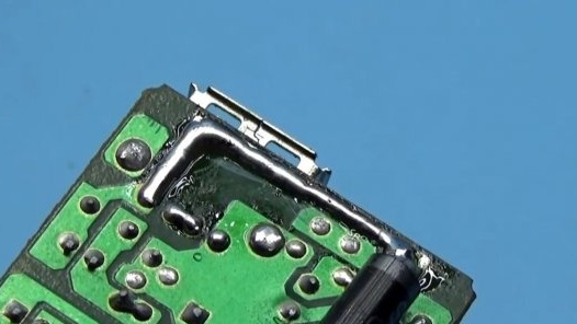
Next, we rummage through the reserves and find almost any Schottky diode with a current of 2-3A, in this case it is a 3 amp sb340.
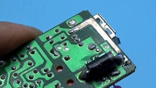
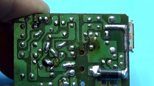
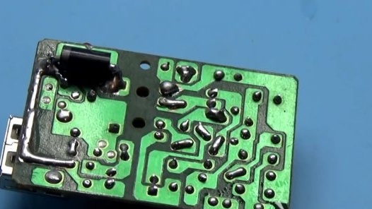
It is quite large and is located next to the output electrolytic capacitor. Capacitors do not like heating, and the diode will just warm up, so it was installed on the back of the board, that is, on the side of the tracks.
From the plus line, just in case, the author strengthened the track with solder.
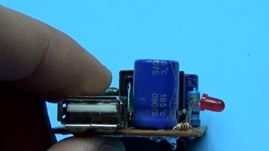
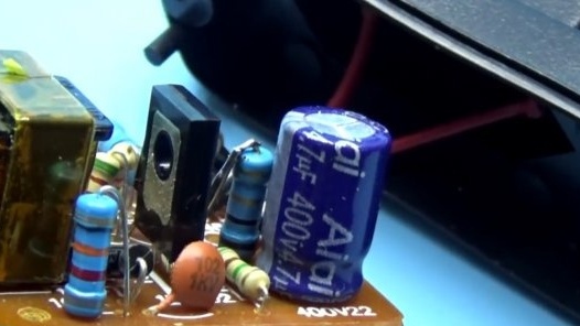
Next, we solder the input and output capacitors, both of them are electrolytic. The output costs 10V 470 microfarads, at the input of the high-voltage 400V 2.2 microfarads. The output capacitor should preferably be supplied with a low internal resistance. You can tear out such capacitors from computer power supplies.
The author found a capacitor at 1000 microfarads, in principle, enough for 470 microfarads. The second capacitor is replaced by the same, only 4.7 uF. Ideally, it is desirable to put the microfarad at 10, but there is not enough space in the case, so this is the solution.
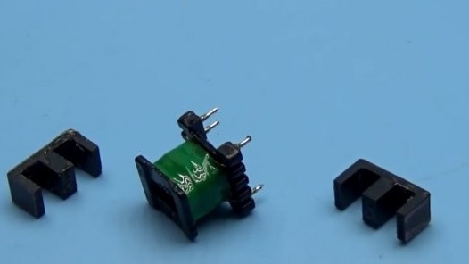
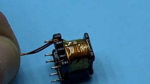
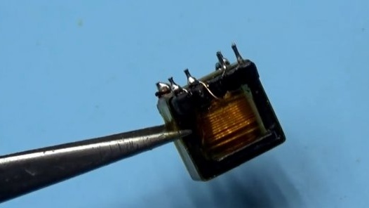
Capacitors must be checked for serviceability: leakage, loss of nominal capacity and internal resistance. Then the fun begins. We evaporate the pulse transformer, remove the tape and throw the trance into boiling water for a minute, so that the glue weakens, and then carefully disconnect the halves of the core.
After that we remove the layer of adhesive tape and under it we find a thin winding - this is our basic winding, it is wound with a 0.15 mm wire and consists of 13 turns. By the way, the secondary winding of the transformer also contains 13 turns, this winding is carefully removed. After our alteration, it will need to be wound back, but the length of the wire is no longer enough, so the wire from it will no longer be useful to us. It is wound with a wire of 0.3 mm, hence such an insignificant output current.
Then we take a wire of 0.45 mm, put it in two and wind 13 turns onto the frame. There was a winding of 0.3 mm, and it became 2 by 0.45 mm, there is enough space on the frame.
All windings are wound in exactly the same order and direction as in the case of factory winding, so as not to confuse the beginning and end of the windings. That is, take a couple of pictures before the unwinding process, so as not to confuse anything. The insulation is heat-resistant tape. Next, we wind the base winding exactly as it was originally wound and again we put the insulation.
Everything is ready, it remains to assemble the transformer. Before assembly, carefully clean both the frame and the core halves from the old glue. We are assembling the transformer, the halves can be pulled together with tape or a drop of superglue, but this should be done only after we make sure that everything is working properly.
We put the transformer in place and, probably, you thought that was all? And no! We have yet to deceive the defense system. It’s a blessing to deceive defense in such a simple scheme. In general, we track the emitter circuit of our main transistor.
The emitter is connected to the input minus through a resistor. This is a low-resistance resistor with a resistance of several ohms, sometimes less, in this case, a resistor of 5.6 ohms.
We have this resistor as a current sensor and at the same time limits the current through the transistor. Protection works in a simple way: the more powerful the output load, the greater the voltage drop across this resistor, and at a certain moment this drop will be enough to trigger a low-power transistor. Opening it, it closes the base of the power transistor to ground and it closes, and, therefore, the output voltage disappears. Everything is very simple.
We change the resistor to a similar one, only with a resistance of 2.2 to 3.3 ohms.
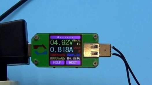
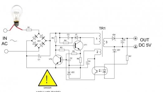
Now everything, it remains only to repeat the test that we did at the beginning. The first start-up of the unit must be done through a 5-10 W safety lamp, this is mandatory, and in no case touch the board during operation, but it is better to close it with something dielectric.
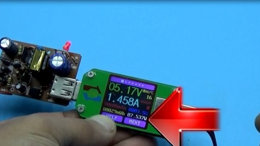
As you can see, at a current of 1 - 1.3 A, we do not observe any noticeable drawdown. The output power of the power supply was almost 8 watts, but at the beginning it was only 4 watts. Result on the face.
This is of course cool, but the core of the transformer needs to be changed, it is now creeping out of one place to provide such power, in short, it works beyond its capabilities. Further, the author straightened out some crookedly soldered components and updated the soldering; in such budget blocks it is extremely unreliable. Well, in the end it will not be superfluous to clean everything from the flux and the power supply is, in principle, ready.
You can end here. Thank you for attention. See you soon!


