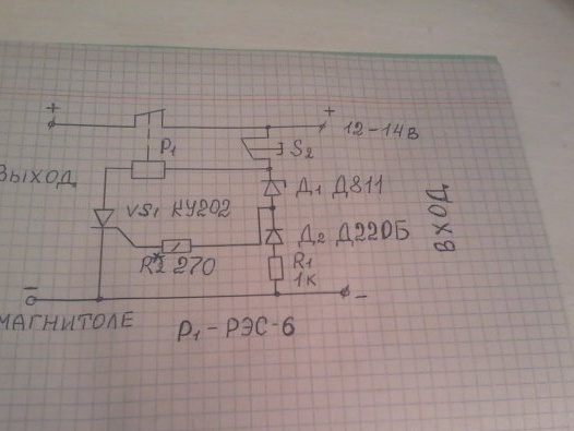
Hello, friends the inhabitants of our site and site visitors! Made another homemade product, which I bring to your attention. One of the main reasons for the failure of the car radio is the malfunction of the car’s relay controller, which, in some modes of the car’s operation, the voltage in the on-board network can rise significantly more than 15 volts. In this case, the radio tape recorders are usually designed for a supply voltage of 11-15V (nominal 13.2V). Here is a diagram of the device
I found her on the Internet. How does this device work? When the supply voltage rises above 14.5 -15, the device turns off the power to the radio. The circuit consists of a thyristor VS1, in the anode circuit of which is connected a relay P1 with open contacts. The current flows to the thyristor control electrode through the Zener diode D1. While the voltage in the on-board network is below 14.5 V, the zener diode is closed. The coil of relay P1 is de-energized and voltage is supplied to the radio through its contacts. As soon as the voltage of the on-board network reaches 14.5 V or more, the Zener diode D1 opens and the current flowing through it opens the thyristor VS1. The relay trips and opens the radio power circuit. In this state, the relay will remain until the S2 button, which turns off the thyristor, is pressed briefly. But before you press the S2 button, you need to eliminate the cause of the voltage increase in the on-board network, otherwise the thyristor will again turn off the car radio. The relay can be used automotive with open contacts. To assemble this device, we need the following parts and tools.
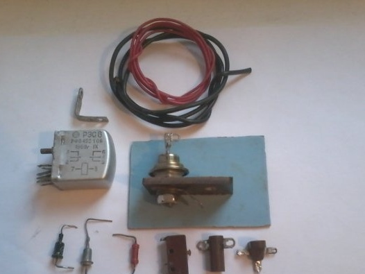
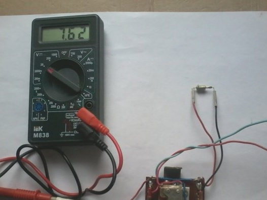
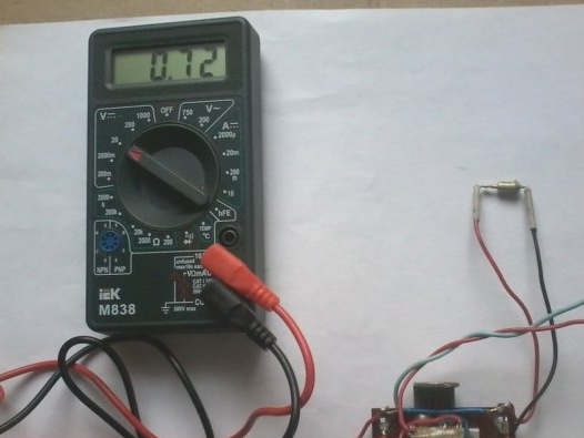
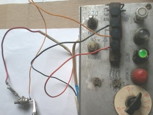
1 - Thyristor KU 202 with any letter index; relay - type RES-6 RFO 452 106; button - to open any; MLT resistor -0.25 W 1 com; and 270 ohms; Zener diode D 811; diode D 220B; any LED and 2 kΩ resistor to configure the circuit; mounting wires; textolite board, size 7 by 4 cm; mounting petals. 2 - Soldering iron; solder; tweezers; nippers; pliers; drill; drill ; M 3 screws and nuts. Assemble the circuit as follows. step 1. I check all the radio components for their serviceability with a multimeter and my device for checking radio components
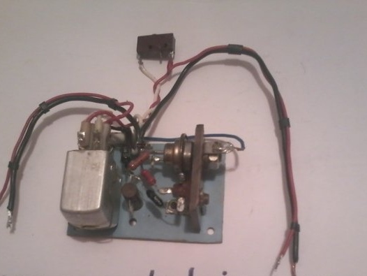
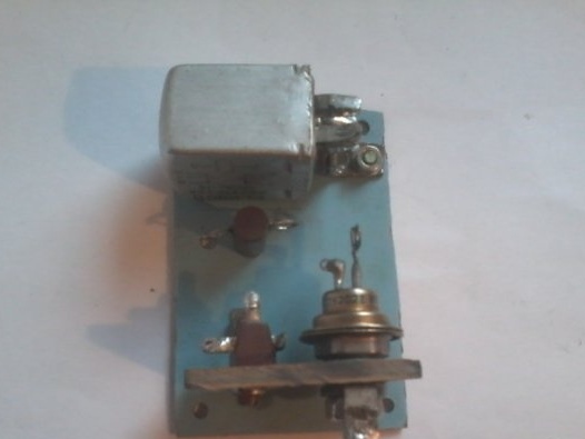
Step 2 We fix the thyristor, relays and mounting petals on the circuit board
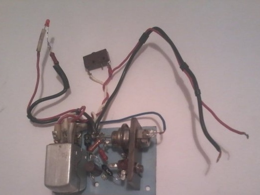
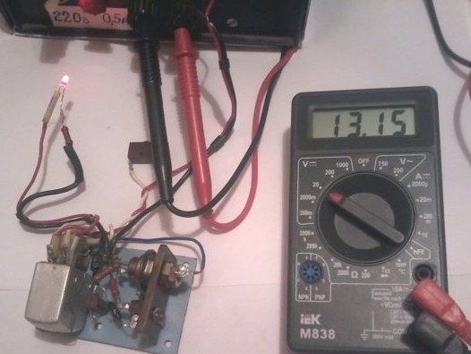
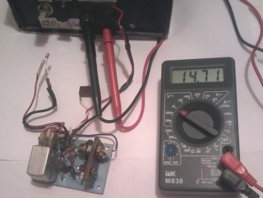
Step 3 We solder the entire circuit, while connecting to the output of the circuit an LED and a 2k resistor instead of the radio
Check the correctness of the assembled circuit. Step 4 set up the device
To do this, instead of resistor R2, we connect a variable resistor SP -1A for 1 com, we connect a supply voltage of 12.5 - 13.2 V. In this case, the LED should light up, then increase the input voltage to 14.5 -15V - the LED should go out. If it does not go out, then rotating the variable resistor R2 engine, we make sure that relay P1 works and turns off the LED (in our case, the load). After that, we measure the resistance of the variable resistor and install a constant resistor of the desired value in the circuit. The relay contacts are soldered in parallel to increase their cross section when the load current passes through them. With a small number of parts, the device works reliably, protecting the car radio. Now it remains only to place the assembled device in a suitable-sized case, and install in car . That's all about this homemade product. I wish you all success in your work.


