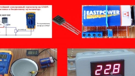
The basis will be a special microcircuit type LM35 obtained with Aliexpress (price about 30r).
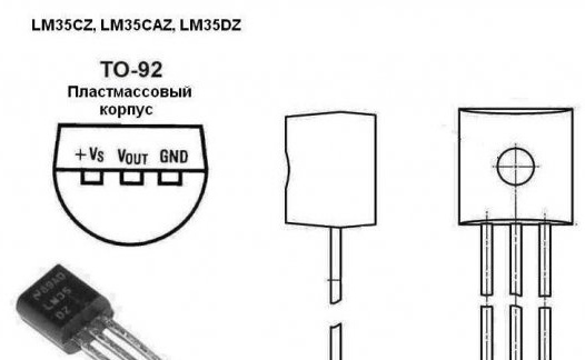
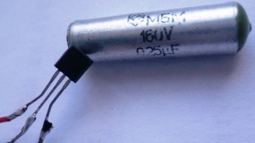
This temperature sensor looks like a normal transistor in a plastic TO92 case (it can be made in other cases: TO-46, TO-220 and SO). It can measure temperature from -55 to + 150 ° C.
Due to the almost linear dependence of temperature on the output signal, fairly accurate readings are provided. For example, at + 20 ° C the output of the sensor will be 200 mV, and at + 100 ° C-1000 mV.
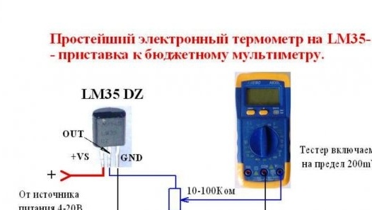
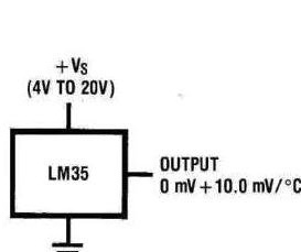
Scheme of using LM35 when measuring temperature from +2 to + 150 ° C.
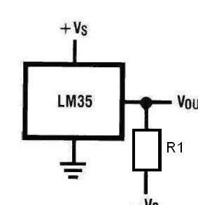
Scheme of using LM35 when measuring temperature from -55 to + 150 ° C.
To make this homemade will need:
- -1 PC;
- tester -1pcs;
- tuning multiturn resistor any from 10 kOhm to 100 kOhm - 1 pc;
- bread board;
- a metal casing from the MBM capacitor or a -1pcs metal tube;
- silicone sealant;
- battery "Krona" or any voltage of 3 V;
- digital voltmeter-1pc;
- connecting wires;
- soldering iron;
- terminal block.
Step 1. Assembling the prefix to the tester.
We will collect the main board electronic a thermometer.
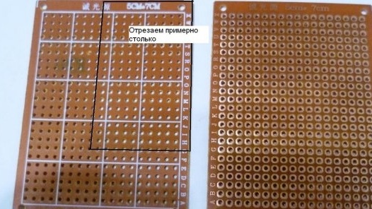
From the breadboard we cut off a piece of the right size to accommodate the battery, terminal block and tuning resistor. You can make a printed circuit board or arbitrarily solder the circuit on any dielectric material.
Connections on the back of the board can be made by wire mounted mounting.
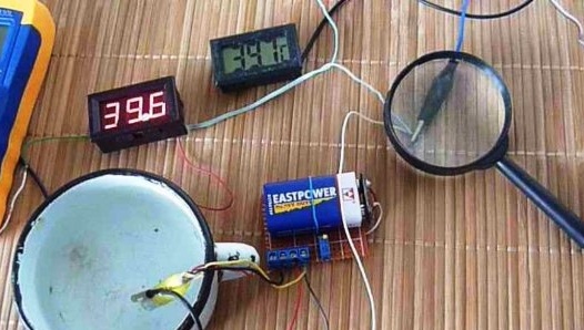
We connect a temperature sensor and terminals to the multimeter to the terminal block. If the sensor will be used outdoors or in a humid environment, it must be placed in a protective cover. I made it from an MBM-type capacitor housing — removed the foil from it and placed the sensor itself there. For sealing, filled with silicone sealant.
Step 2. Configure and test the console.
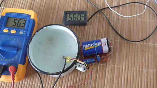
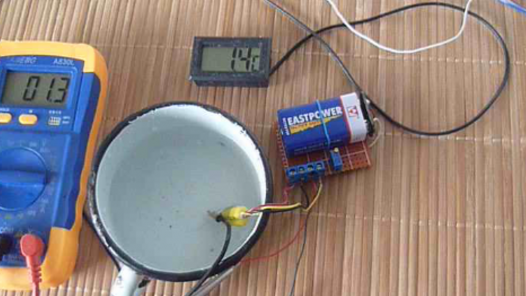
We connect power and a tuning resistor, we adjust the readings for another thermometer. The multimeter is switched on to a measurement limit of 200 mV. Then he compared the readings by placing the sensor in cold and hot water. The difference was in tenths of a degree.
On this, the setup is finished, you can use the LM35 thermometer as a prefix to the tester.
Step 3Converting a voltmeter into a thermometer.
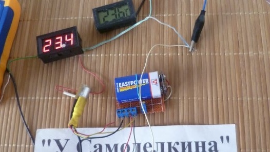
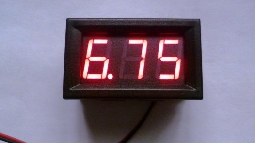
You can also use this prefix as a base and make an electronic digital thermometer from an electronic voltmeter.
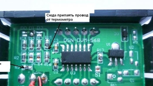
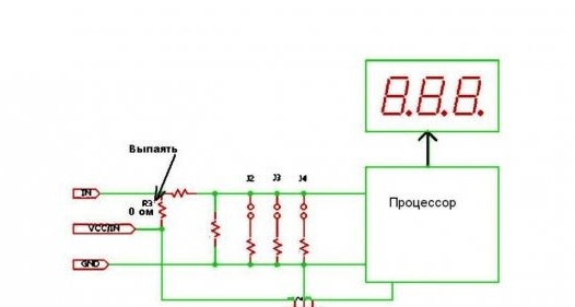
It was turned on in a two-wire circuit, we connect it to a voltage source and it is powered by it and shows the voltage value. It is necessary to redo it to a three-wire power circuit separately and the measuring input separately. This is easy to do, you need to remove the resistor R3 (resistance 0 Ohm). This will give another opportunity (if you use a voltmeter for its intended purpose) to expand the limit of measurement. In a two-wire circuit, the measurement limits are from 4 to 30 V, in a three-wire circuit it will be from 0 to 100 V.
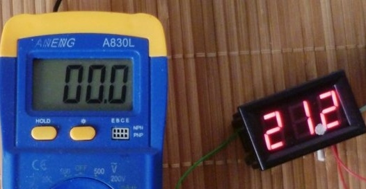
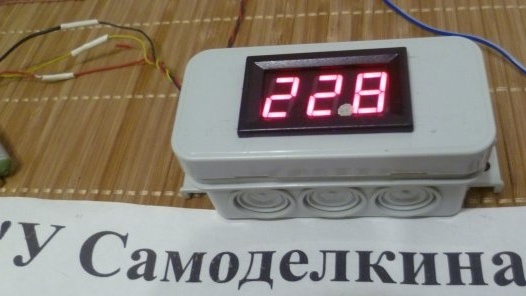
Solder the temperature output from the console on the LM35 to the processor (to the point indicated in the photo). We seal the burning point on the voltmeter with black electrical tape, after the second digit of the voltmeter we paste the white point.
It remains to set the real temperature on the voltmeter with a tuning resistor. We also check the readings on the model thermometer.
The last step in making a homemade product will be placement in a suitable case. I found a small distribution box - it just fit both a scarf and a voltmeter. The wires of the sensor and power go out. You can power the circuit from the battery and place it in the case, then the device will be completely autonomous.
The LM35 sensor has a wide range of applications. It is used in the on-board computers of cars, in thermostats, goes well with Arduino. It all depends on your needs and fantasies.
The video shows in more detail how to make a prefix for a budget tester and remake a voltmeter into a thermometer.


