An option is proposed for manufacturing a battery charger for household appliances, with setting the current and charging voltage, with stabilization of the current at the load.
With periodic living in a summer house, sometimes it becomes necessary to recharge various power sources for a watch, receiver, flashlight. In addition, Li-ion batteries from older mobile phones used in previously manufactured ones require a charge. homemade. Given that the batteries used have different shapes, dimensions and mounting dimensions, as well as different charge modes, it is necessary to make, to some extent, a universal charger (charger). Since this charger will be used only periodically, it makes no sense to manufacture or acquire specialized memory for each type of battery.
In this regard, to charge various low-power batteries, we will produce a single, simplified, but reliable charger. When charging batteries under periodic visual control over the end of the charge, having the ability to set modes (stable current and maximum charge voltage), such a charger will ensure high-quality operation.
The manufacturing process of the charger for the task is discussed below.
1. Installation of the source data.
For the proper operation of nickel-metal hydride batteries, it is recommended to maintain the operating voltage on the cells within 1.2 ... 1.4 volts, the maximum reduction to 0.9 volts is allowed. It is recommended to carry out fast charging of NiMH battery cells at a voltage of 0.8 ... 1.8 volts, with a charge current in the range of 0.3 ... 0.5C.
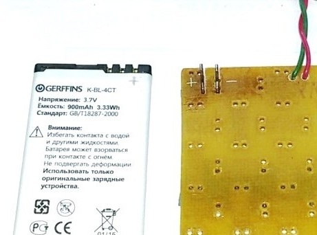
The operating voltage for a Li-ion battery is 3.0 ... 3.7 volts. The battery must be charged to a maximum voltage of 4.2 volts, with a charge current in the range of 0.1 ... 0.5 C (up to 450 mA with a battery capacity of 900 mAh).
Given the recommendations, we establish the following characteristics of the manufactured memory:
The output voltage is 1.3 ... 1.8 volts (for a NiMH battery).
The output voltage is 3.5 ... 4.2 volts (for a Li-ion battery).
Output current (adjustable) - 100 ... 400 mA (... 900 mA).
Input voltage is 9 ... 12 volts.
Input current is 400 mA (1000 mA).
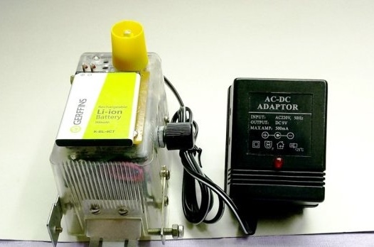
2. Current source.
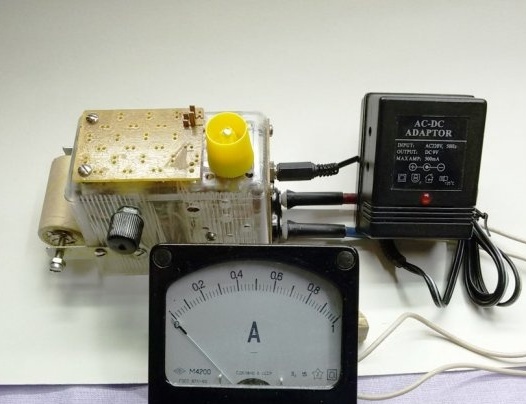
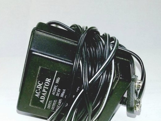
As a current source for memory, we use a mobile adapter 220/9 volts, 400 mA. You can use a more powerful adapter (for example, 220 / 1.6 ... 12 volts, 1000 mA). In this case, changes in the design of the memory are not required.
3. Charger circuit.
The memory circuit is easy to manufacture and commission, it does not have scarce and expensive parts. The device allows you to charge various batteries with a stable, pre-installed, current. And also, before starting charging, you can set the voltage limit, above which it will not rise at the battery terminals, during the entire charging process.
Let's make the memory according to the scheme.
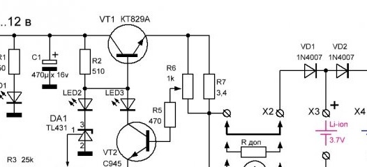
4. Description of the operation of the memory circuit.
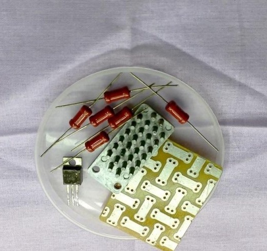
The output current control unit is built on a VT1 composite transistor. The maximum value of the output charge current is limited by the low-resistance resistor R7 (with the ratings of the parts indicated on the diagram and the corresponding power supply unit, the maximum charge current of the Li-ion battery reaches 1.2 A). In the absence of a resistor, the necessary resistance and power, it can be assembled from several cheap and common resistors. For example, in the above design, the three-watt resistor R7 with a resistance of 3.4 Ohms is assembled from two series-connected groups, three parallel resistors MLT-1 with a resistance of 5.1 Ohms.
On the transistor VT2 and resistors R5, R6, a stabilizer and a charge current regulator are implemented. The variable resistor R6 is connected in parallel with the limit resistor R7 and is a current sensor. The current through resistor R6 is proportional to the current through resistor R7, but due to the ratio of resistances it is much smaller, which allows you to control the output current using an alternating resistor and a low power transistor.
Under load, a voltage drop appears in the current sensor proportional to the passing current. When the charging current changes, for various reasons, the voltage drop across R6 and, accordingly, the control voltage based on the VT2 transistor changes proportionally.
With increasing voltage on the basis of VT2, the current K-E of the transistor VT2 increases, reducing the voltage on the basis of VT1. In this case, the power transistor VT1 begins to close, reducing the charging current of the battery. Conversely, with a decrease in voltage based on VT2, the charging current increases. Thus, automatic correction of the current in the load is carried out - stabilization of the charge current.
By changing the resistance of the resistor R6, we can set the required battery charge current. After adjustment, similar processes of stabilization of the newly set current occur.
The node for setting the limit voltage is made on an adjustable voltage regulator DA1 (TL431). Selecting the resistance of resistors R3 and R4, we select the optimal voltage control range. Using a variable resistor R4, we set the output voltage limit (before connecting the battery to the charger).
When you connect a discharged battery to the charger, the output voltage decreases. The current set by resistor R6 begins to flow through the battery. As the charge and increase the voltage on the battery, the potential at the control electrode of the zener diode DA1 approaches 2.5 volts, the zener diode TL431 begins to open. At the same time, the voltage based on VT1 gradually decreases, the power transistor closes, and the charging current flowing through it gradually decreases to almost zero.
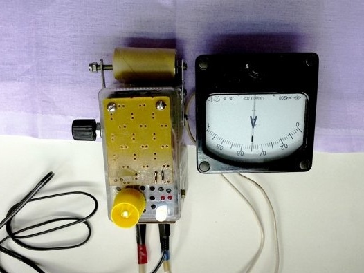
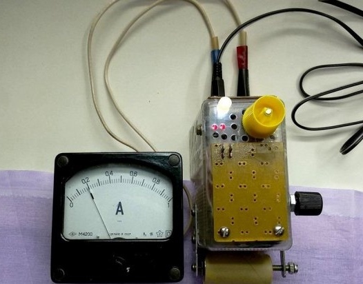
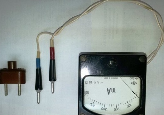
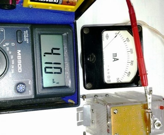
An ammeter (multimeter) is included in connector X2 for setting and monitoring the charging current; when charging elements of the same type, a jumper is installed instead.
X3 connector is used to install a Li-ion battery from a mobile phone. It is possible to install cylindrical batteries of various lengths with a voltage of 1.2 ... 1.4 volts in connector X4. Diodes VD1 and VD2 are included in the X4 connector circuit to lower the battery charge voltage to 1.3 ... 1.8 volts and to prevent battery discharge when the charger is turned off. Using remote probes with a clip, you can connect a non-standard battery with an operating voltage of up to 6 ... 9 volts for charging.
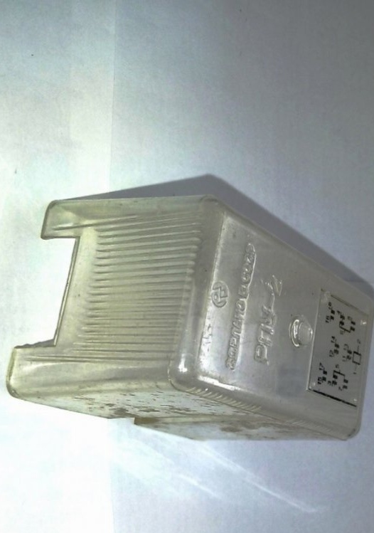
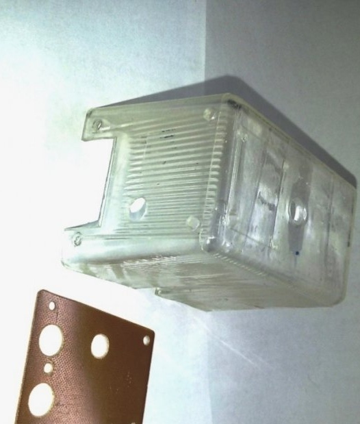
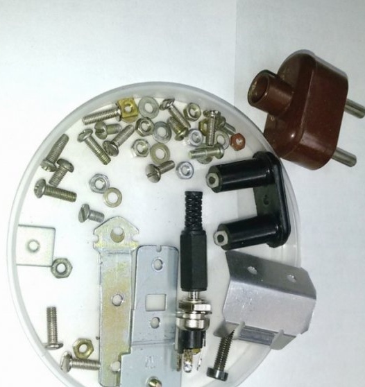
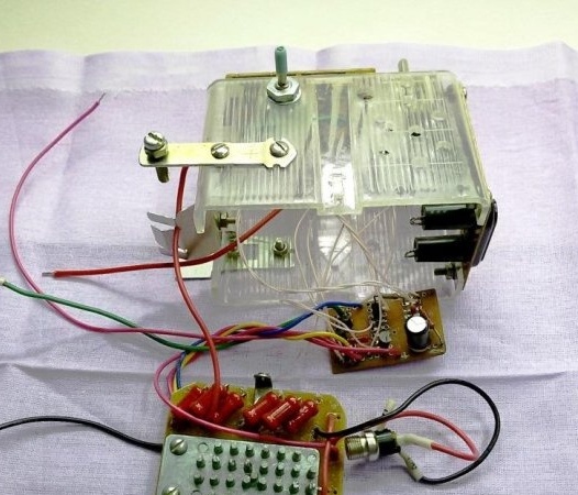
5. Making the charger housing
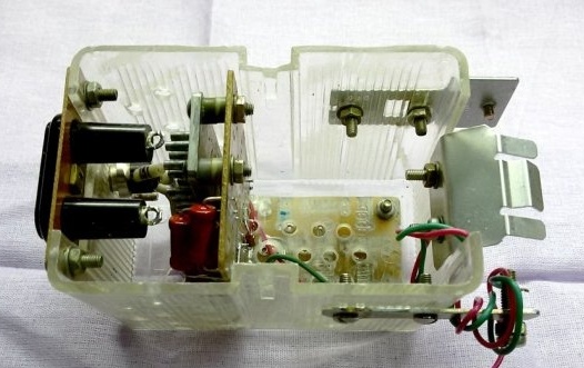
For the housing of the memory we use a plastic cover from an old relay, measuring 90 x 60 x 65 mm. We reinforce the case with a PCB panel for installing connectors. We drill the required mounting holes.
6. We complete the case with connectors and manufacture non-standard elements.
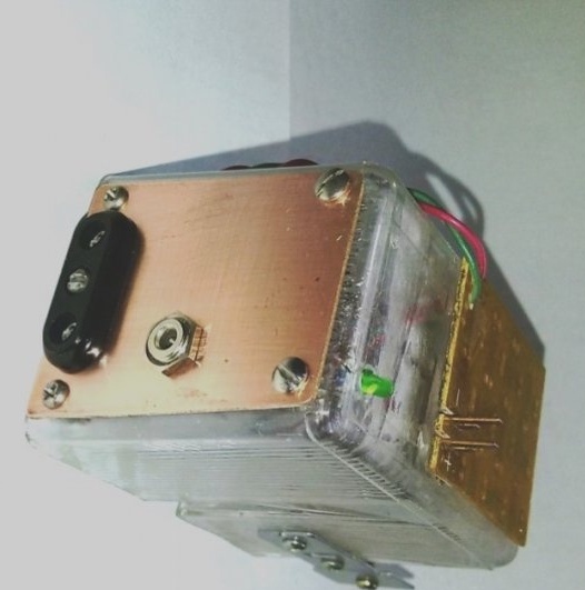
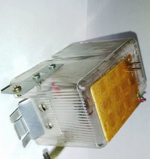
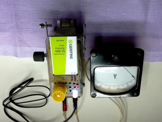
7. We assemble the case with hinged elements. On the rear panel there are connectors - control X2 (bottom) and input X1 for connecting to the charger power adapter. At the top of the case is a panel for installing a Li-ion battery.
8. The lodgement is fixed on the front side of the memory and contacts for installing cylindrical batteries.
9. We complete the memory with parts in accordance with the above diagram.
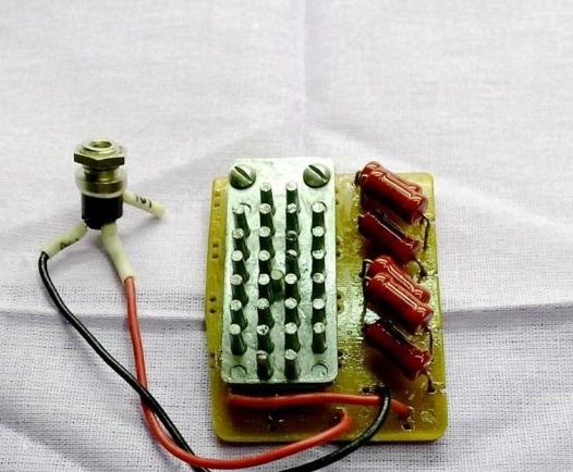
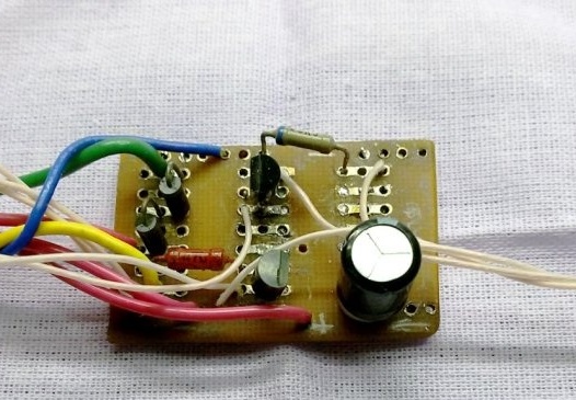
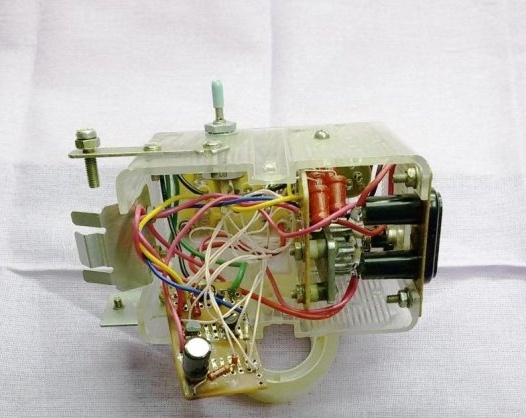
We postpone parts that have a lot of heat. In this case, it is a power transistor VT1 on a radiator and a assembled resistor R7, composed of six resistors of lower power. To improve the temperature regime, we collect these parts on a separate board. The remaining parts are installed and soldered on the second board.
The dimensions of the boards are determined by the internal dimensions of the case and their location in the volume of the case. Having decided on the location of the boards, we drill holes in the case for variable resistance and ventilation holes for heat dissipation.
10. Assembly of memory
According to the memory scheme, we collect the power and control boards together, we check the operation of the circuit.
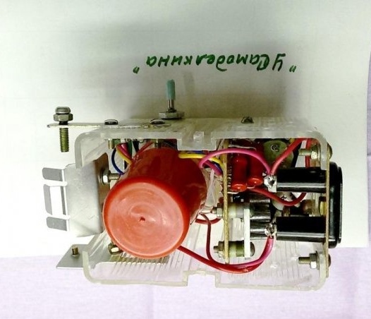
We install and fix all the accessories in the housing. To exclude possible electrical contact, we isolate the control board from the environment with a plastic cap.
We assemble the design of the memory as a whole and check the operation of the device.
11. The work of the charger.
Before connecting the Li-ion battery to the charger, using the variable resistor R4 (voltage regulation), we set the charge limit on the output terminals for this battery.
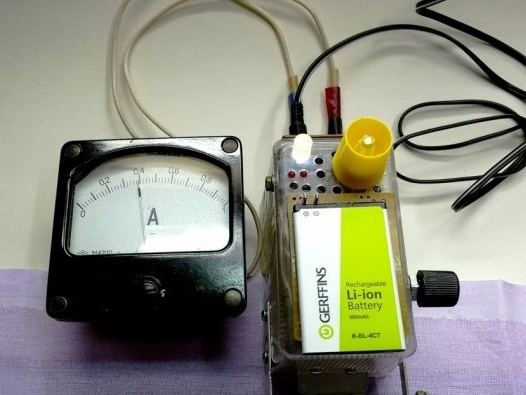
We connect the battery, the output voltage decreases to the residual voltage on the battery. By adjusting the resistance of the resistor R6 (current adjustment), we set the required charging current.
When installing a cylindrical battery cell, the process of selecting modes is similar.
When the charger is turned on, before installing the battery, the voltage stabilizer DA1 opens (the voltage at the zener diode control electrode is higher than 2.5 volts) and LED2 (red indicator, left) lights up.
We connect the battery, the output voltage decreases. Charging starts with the set stable current. LED2 goes out. Depending on the set current, some illumination of the LED3 (red indicator, right) is possible.
When the set voltage is reached, the charge continues at this voltage, but with a decreasing charge current. The brightness of LED3 increases, LED2 turns on. The maximum brightness of LEDs LED2 and LED3 indicates the minimum charging current inherent to the end of battery charging.