Good afternoon, today I took up the idea of creating a device for copying electronic keys such as Touch memory or ibuttom. Also known as “pills.” Such keys, although already quite outdated, were replaced by contactless Rfid, but are still often used for intercoms or burglar alarms. The basis of our device will serve Arduino Uno. You can use any other Arduino compatible board. To be able to use our device autonomously, without a computer, you need a power supply from 6 to 12 volts. To indicate the status of the device, we will use the WG12864B graphic screen. We also need a case, in this case the box from the Sega cartridge is perfect.
To implement this idea you will need:
- Arduino UNO (Or Arduino compatible board)
- WG12864B graphic screen
- Resistor 100 Ohm 0.25 W
- Power supply 6 - 12 V
- Resistor 2.2 KOhm 0.25 W
- Resistor 10 KOhm 0.25 W
- Box from the cartridge of the SEGA console
- electrical tape
- connecting wires
- Button
- A small piece of stainless steel
- metal scissors
- Stationery knife
- soldering iron
- Solder, rosin
- Double sided tape
Step 1 A bit about the Ibuttom keys themselves.
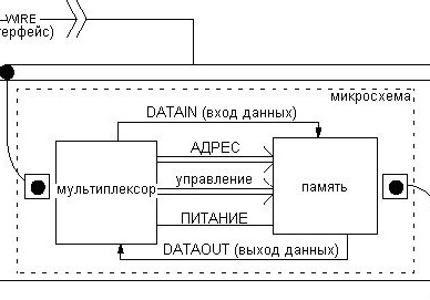
To make it clear iButton is just a chip crammed into a round stainless steel case. Case diameter 16.3 mm. The stainless steel case is resistant to shock, dirt and moisture. The housing standard is called the iButton MicroCan. Available in two standard thicknesses: 3.1 mm (version F3) and 5.9 mm (version F5). The microcircuit receives power from the data line of the master device. The diameter of the cover is the same for all versions. Therefore, the same reading cup is suitable for everyone. Block diagram of our keys:
Keys are rewritable and not. To make a duplicate, you will need, respectively, rewritable. There are 3 versions of tags: RW1990, TM08v2 and TM-08 VZT F. They differ in the microcircuit inside. The most common RW1990. They can be bought at aliexpress or a fire alarm retail store.
Step 2 Screen.
We will use a liquid crystal display, a resolution of 128 by 64 pixels. Most of them work on ks0107 / ks0108 chips, so there should not be a compatibility problem. All these screens can be divided into 4 types. Different connection:
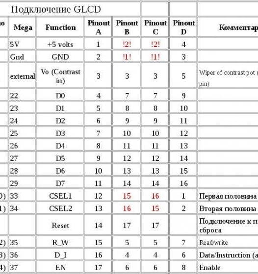
It is best to take WG12864B3 V2.0, it can be easily found in both Chinese and Russian stores. There may be several types of backlighting, but this does not affect the functionality in any way.There are also two connection options: parallel and serial. When choosing a parallel type, we need 13 free Arduino pins. Choose sequential. Only 3 conclusions are involved here. And do not forget about nutrition:
WG12864B - Arduino UNO
1 (GND) - GND
2 (VCC) - + 5V
4 (RS) - 10
5 (R / W) - 11
6 (E) - 13
15 (PSB) - GND
19 (BLA) - via a 100 Ohm resistor - + 5V
20 (BLK) - GND
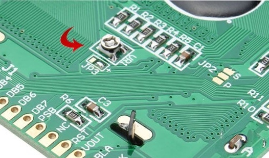
The brightness of the screen is regulated by a potentiometer located on the board with the screen. If it is - the ability to adjust the brightness is absent, but this rarely happens:
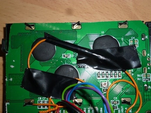
A resistance of 100 ohms is used to reduce the voltage for screen backlighting. We insert it into the section of the wire that feeds the backlight:
Step 3 Housing and reading cup.
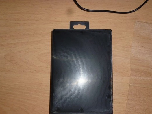
So that we do not have a "dzhigurdy", and everything looks normal, we will begin manufacturing the case. Any plastic box that fits the Arduino Uno and the screen is perfect. The best solution is a cartridge box.
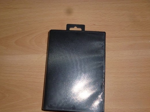
Cut the loop box and remove the film:
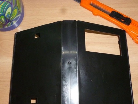
We pick up a clerical knife and begin to cut out the slots. First, cut out the largest one at the top of the box, size 37x69. It is needed for the screen.
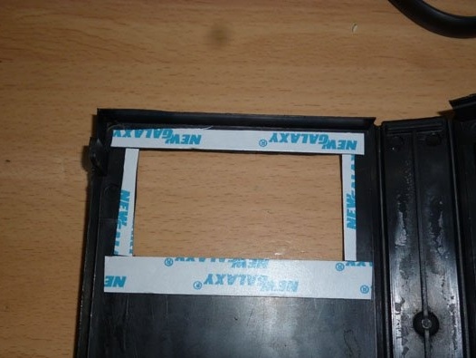
Glue double-sided adhesive tape inside the box:
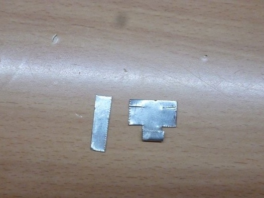
Now we are puzzled by a readable cup. You can buy and use the finished one. This is the easiest option. I'll show you how to make this cup myself. We cut out two rectangles from a stainless steel: 20x20 mm and 20x8 mm:
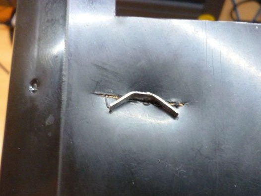
We make a small slot at the bottom of the screen and insert a bigger rectangle there:

And bend the edges:
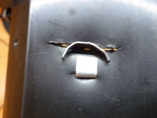
And on the reverse side, we also do to fix the negative contact plate:
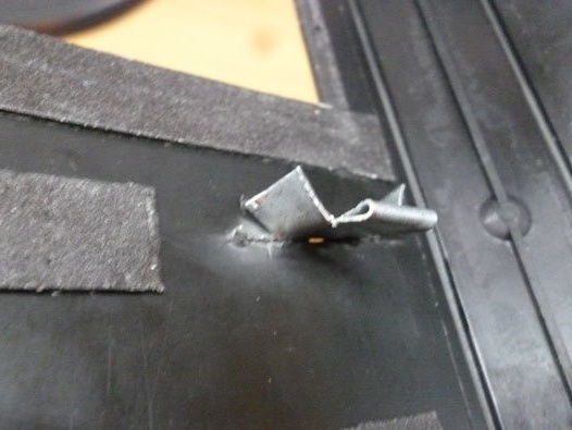
For plus, we also make a slot and insert a positive contact into it:
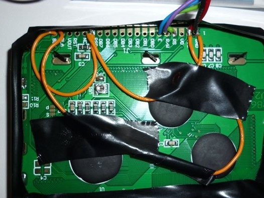
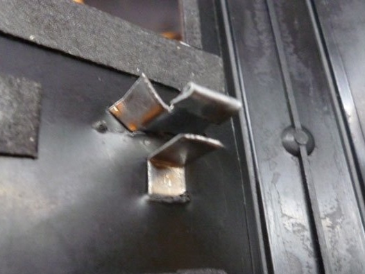
From the inside, the contacts look like this:
On the previously pasted tape we fasten the screen:
Outside it should be like this:
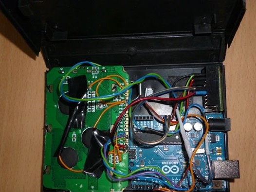
Inside the box, below the screen, we place the Arduino:
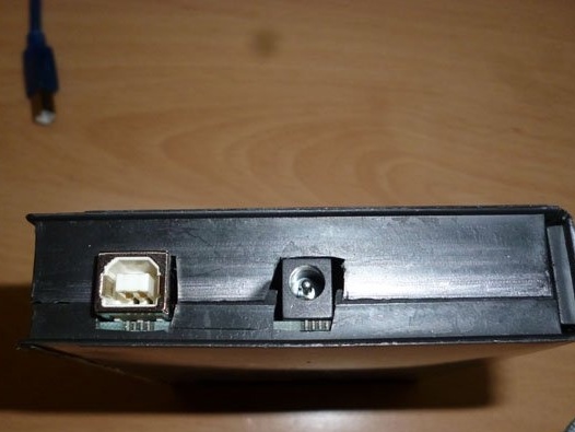
Remember to make slots for the USB and power jacks:
To switch modes between reading and writing, output the button:
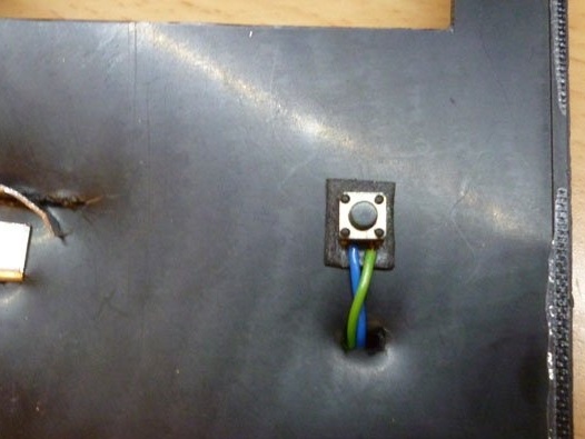
Step 4 Solve the issue of nutrition.
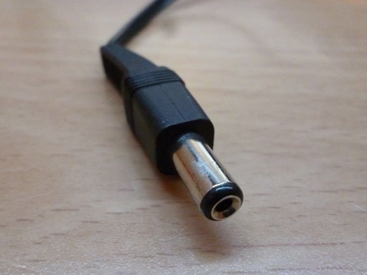
In order for our device to work, we will provide it with power. For this we need a power supply. The voltage should be between 6 volts and 12. The plug at the end should fit into the Arduino socket:
You can do without a power supply. You can power the device from a USB computer. If you want, you can take a compartment for 4 AAA size batteries and stuff it in. Then the pin output must be connected to the Vin of the Arduino board.
Step 5 Putting it all together.
The reading bowl is connected according to the scheme:
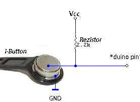
We connect the positive contact of the bowl to pin 7, pulling it through the 2.2K resistor to VCC. We connect the button to pin 6, pulling a 10K resistor to GND.
Step 6 Software part.
Download and install Arduino IDE with
To work with Touch memory, the One Wire library is used. It also needs to be downloaded and installed in the Arduino IDE:
Launch the screen using the U8glib library:
Without libraries, compiling a sketch and uploading it to Arduino will fail. We act in the following ways: unzip the downloaded archives and move these files to a folder named “libraries”. It can be found by installing the programming environment.
Download the archive with the sketch:
Unpack the archive, open the sketch in Arduino Ide and fill it in Arduino.
Step 7 The process of copying keys.
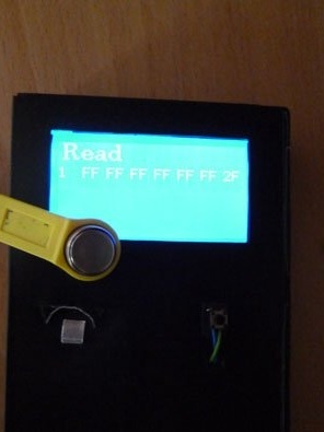
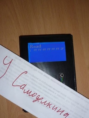
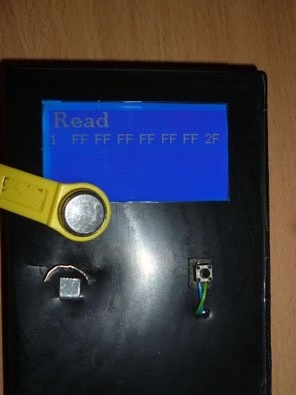
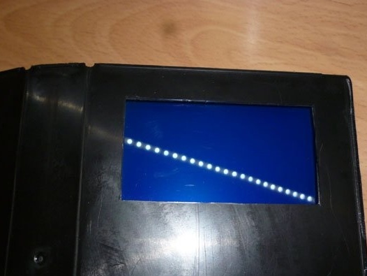
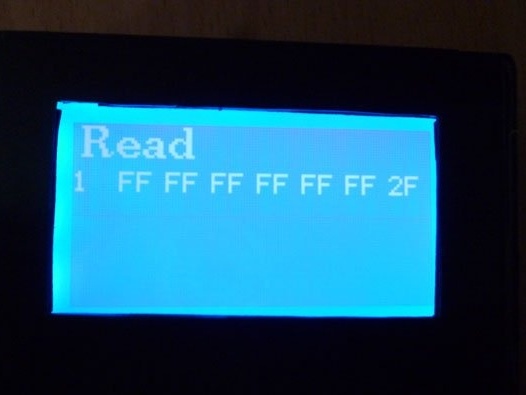
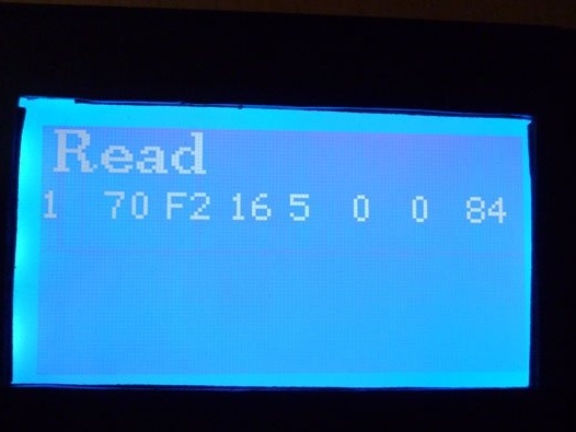
When you turn on our device, the screen will read "Read" and the universal key. This key is written in the sketch. I found him on the Internet. Personally, I did not check how universal it is. If this happens, our device is ready for use:
We apply the key to be copied. This key should be displayed on the screen. For example, I took one of those that I have:
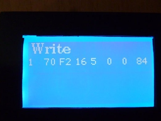
Now presses the button, the inscription on the screen should change to "Write". The key will also be displayed, which will be recorded:
We put a tablet on which we will write a blank, and wait until the text on the screen changes again to “Read”. If this happened - the recording was successful. To check, attach the blank again, the device should read it and display the key.
If you want to record a universal key, just press the button at the very beginning, when the inscription is changed to “Write”, attach a blank.
The device also sends information about the keys and the processes of reading and copying through the serial port.You can open the Arduino Ide terminal or any other terminal program and monitor the copying process in it.
The universal key recorded in the sketch can be changed. To do this, open the sketch and edit the line:
byte ReadID [8] = {0x01, 0xFF, 0xFF, 0xFF, 0xFF, 0xFF, 0xFF, 0x2F};But this is not so simple. The last byte is the key checksum or Cyclic Redundancy Check (CRC). In this case, it is 2F. Without this amount, readers do not accept the key. CRC is calculated by a special algorithm. You can find and calculate this algorithm yourself, but please use our device. The first byte is family code, it must always be 01. Next, it writes the bytes in the string that we want to write as a universal key. Fill the sketch. We write this key on the disc and try to read it back, while opening the terminal window. In the terminal, we will see our key at the end of the CRC. This is the desired checksum. Now edit the sketch again. Instead of the last byte in the same line, write the byte received during reading after the CRC. Again, fill in the sketch and write a new key on the disc. Open the terminal window, try to read our key. The last byte of the key must match the byte written after the CRC.