


The author’s only source of inspiration homemade there was a table lamp and the desire to make the best holder for dremel when using a flexible shaft. He built his first articulated pivot tool stand about 8 months ago, and it worked well. But there was a feeling that he could build it even better, since there was a whole bunch of maple floorboards from the gym. The author decided to update his stand, as there is an ideal opportunity to do this.
If you want to build your own stand, you do not have to use waste. However, a lot of wood is not required for this project, so why not use the waste?
Necessary materials and tools:
materials:
- for this design, the author used two maple floorings 60 cm long, cut into square slats, with a side of 19 mm, plus a bit of additional flooring for the hinge and the hook holder;
- a square piece of plywood with a side of 19 mm;
- 8 bolts 6x 76 mm;
- 8 6 mm nuts;
- 1 carriage bolt 9x10 mm (a regular bolt will do);
- 2 9 mm washers;
- 1 9 mm wing nut;
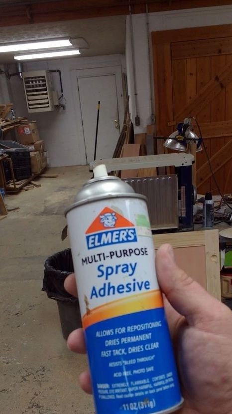
- glue for wood;
- 4 screws 12 mm;
- 5 screw eyes bent into a ring;
- 6 mm steel rod 15 cm long;
- mini gum;
Instruments:
- table saw;
- Jointer;
- hammer;
- Drilling machine;
- Hand drill;
- Hand saw;
- band-saw;
- knife;
- marker;
- scissors;
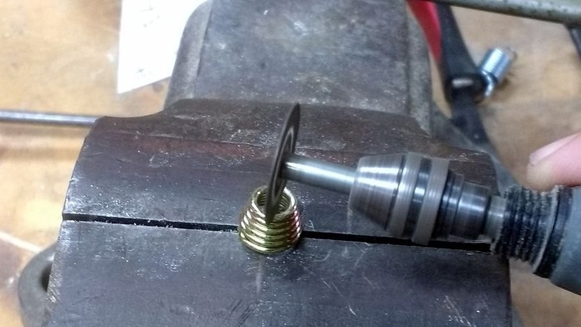
- Dremel with a cutting disc;
Step One: Inspiration and Design
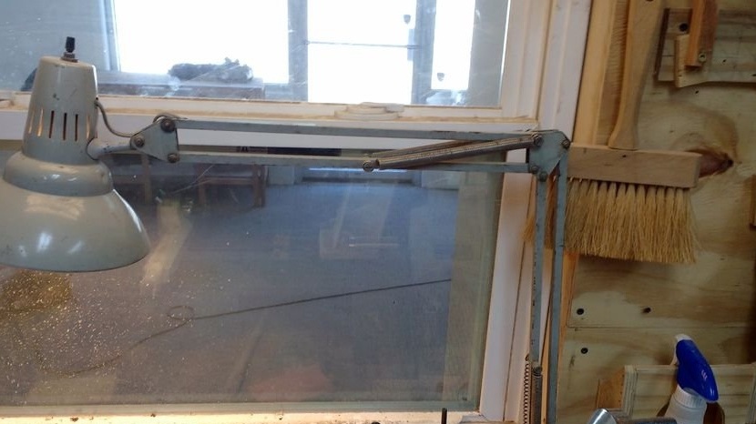
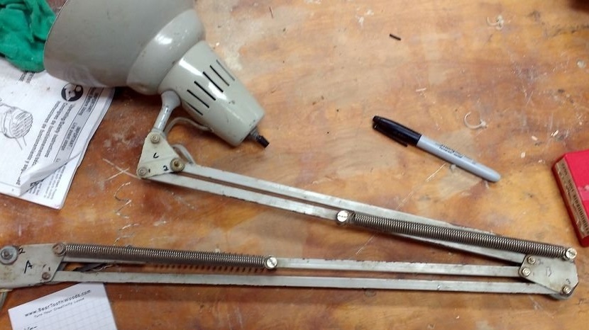
As already mentioned, the author came from the contemplation of a table lamp. A couple of photographs are available.
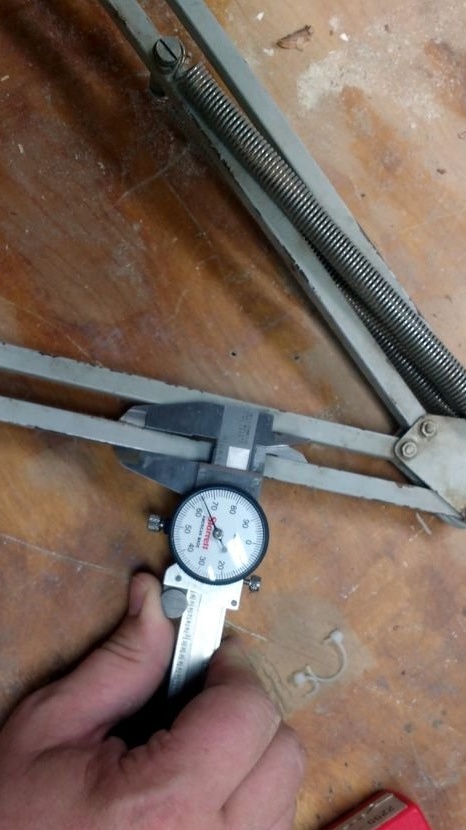
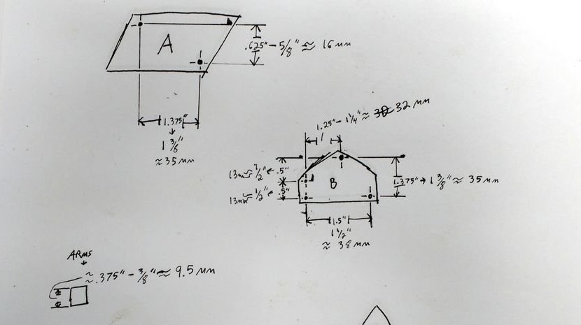
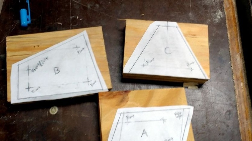
He assumed that he could simply measure all turning points, as well as the length of the rod, divide all these numbers by the thickness of the knees, and get a ratio with which you can smooth everything out!
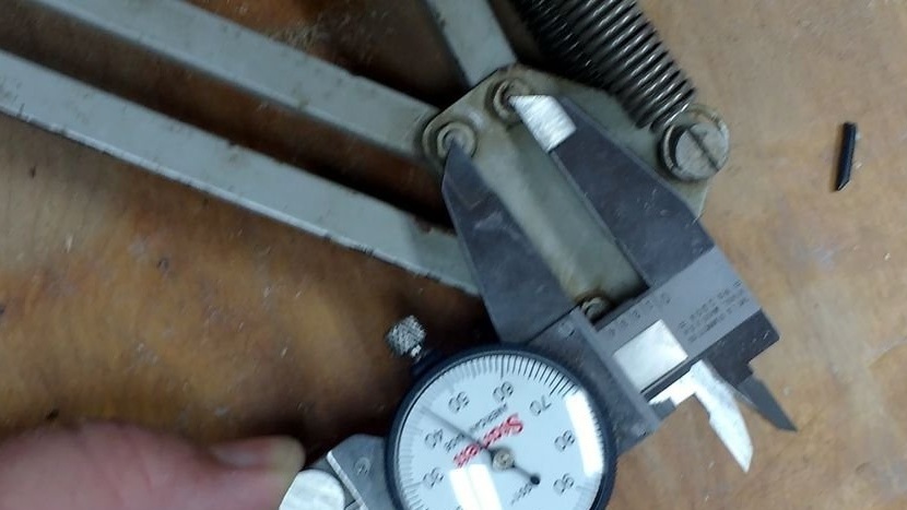
This did not work, but he received the measurements. The upper limb was 35 cm, the lower limb was 45 cm, and the limb thickness was 9 mm. It was planned to add 19 mm to the proportion and use the result, but the lower knee ended in length 91 cm. The author gave up all this work, and did the upper and lower knees 60 cm.
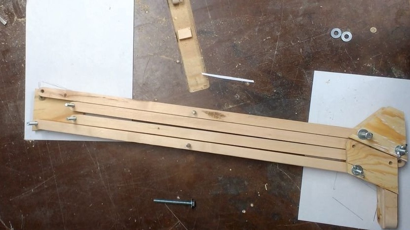
Step Two: Knee Preparation and Cutting
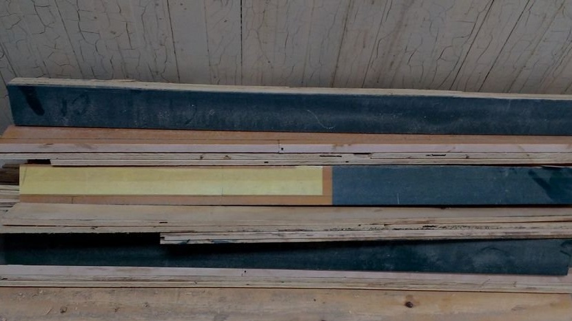
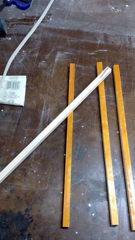
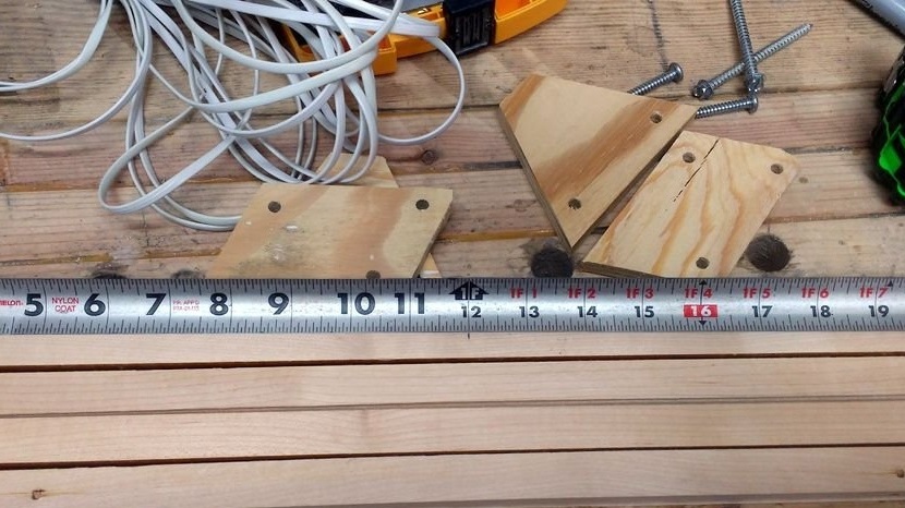
Super easy step, all you need to do is take a board and cut 4 wooden pieces 60 cm long and 19 * 19 mm in size.
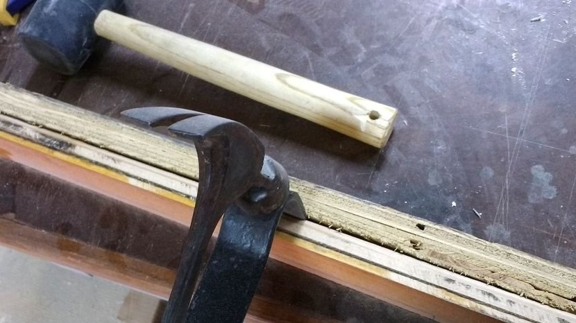
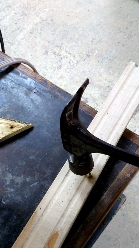
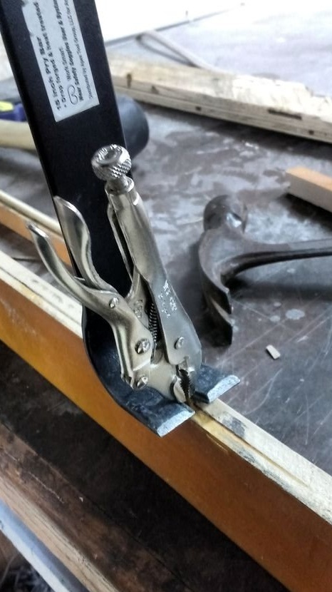
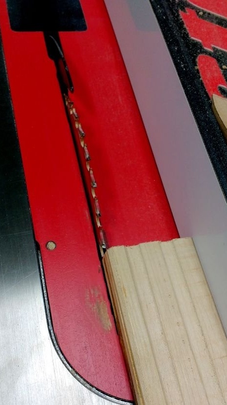
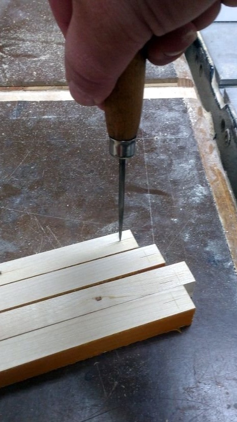
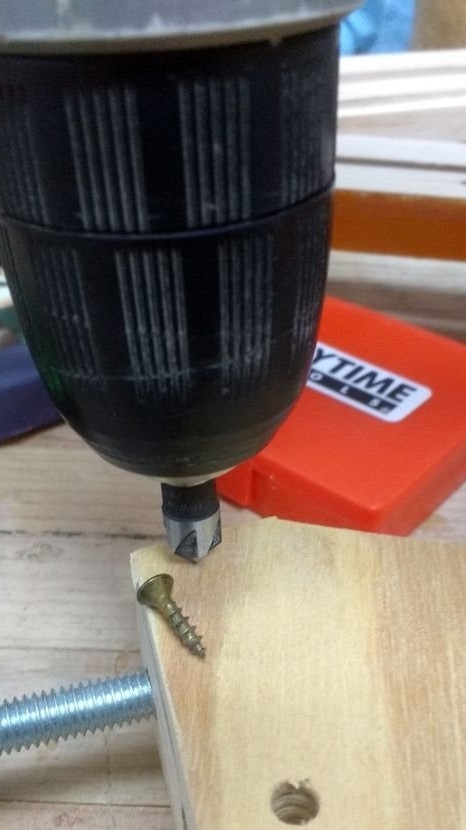
Since the author works with the old floor from the gym, there are nails in it. He pulled out nails and removed the plywood litter.He has his own tricky trick for pulling out nails. See images.
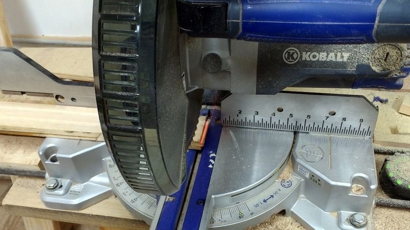
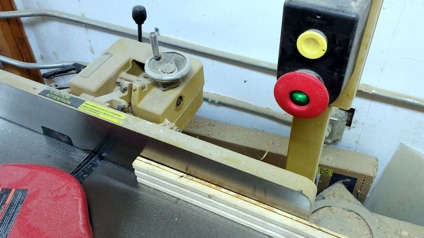
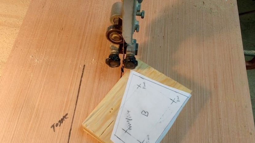
Having pulled out the nails, a saw went to use to cut off the ends of the boards, because the spike and groove interfere.
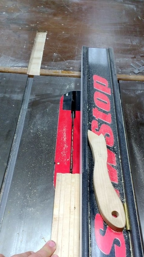
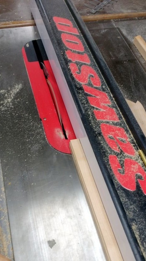
After trimming the ends, he connected the side of the board with the groove, since it was the least damaged, as a result of a previous collision with someone else's saw. After joining, he tore off a rough edge, cut a board up to 60 cm long and cut a square rail with a side of 19 mm. It turned out two slats with such dimensions.
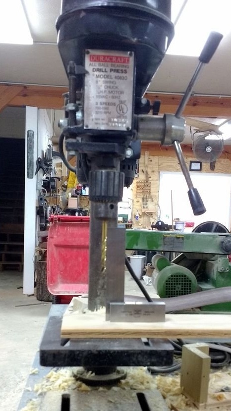
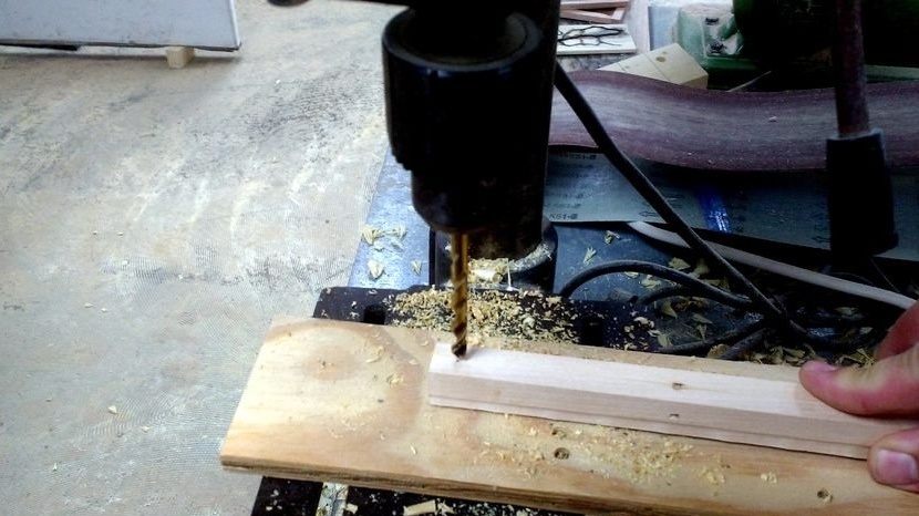
Step Three: Marking and trimming joints, as well as drilling the hinge holes
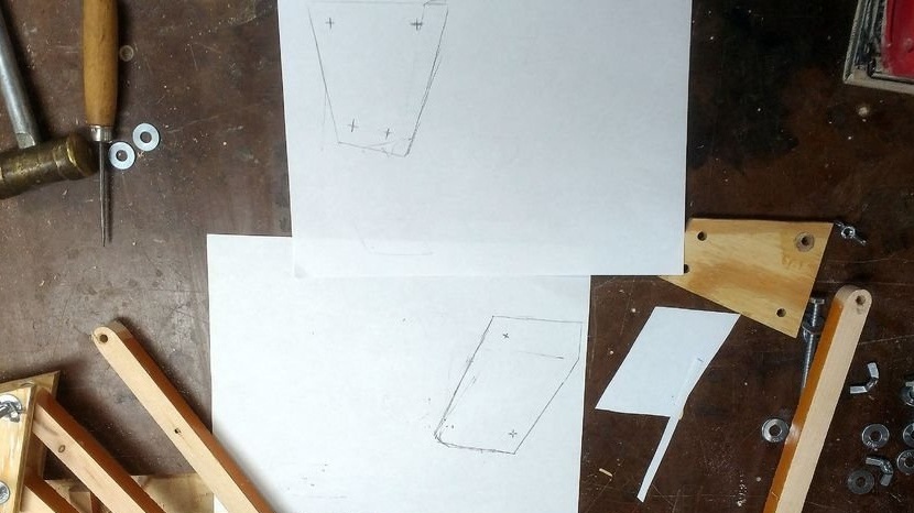
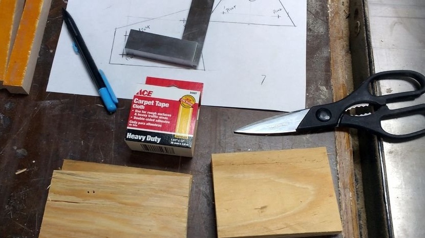
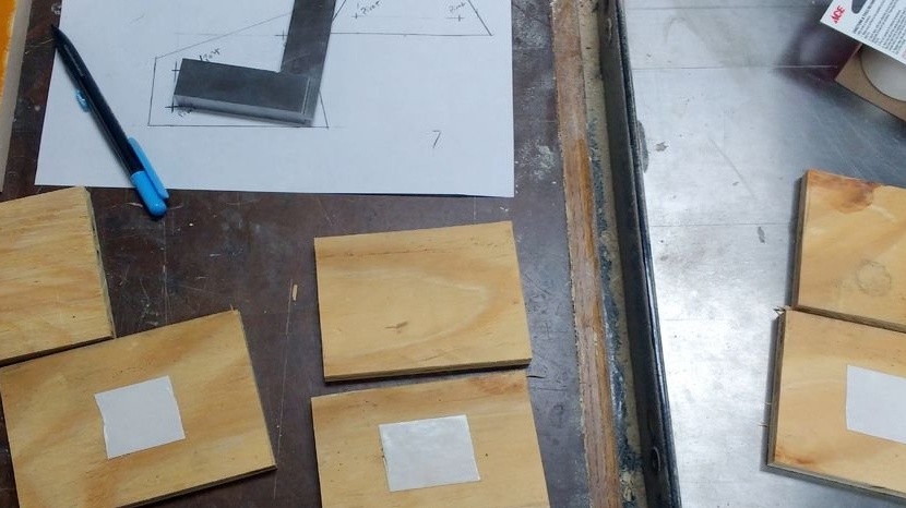
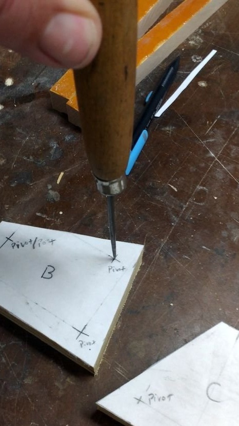
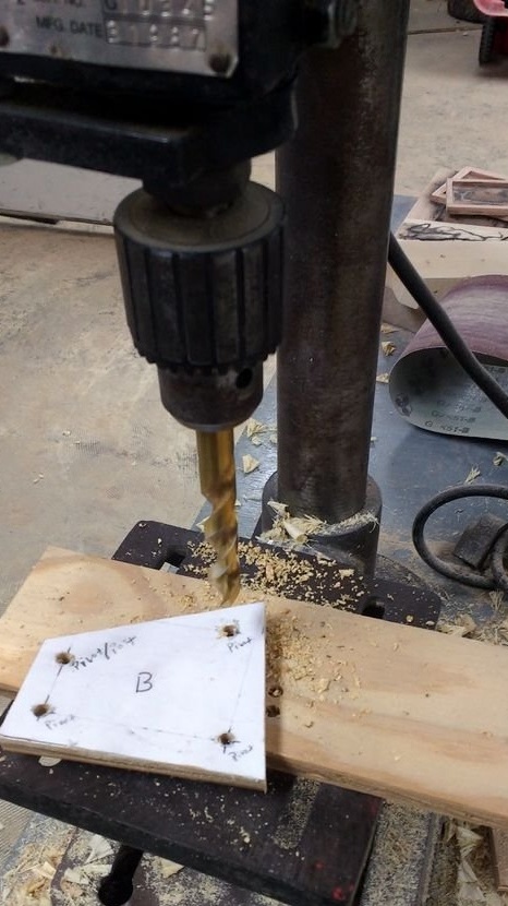
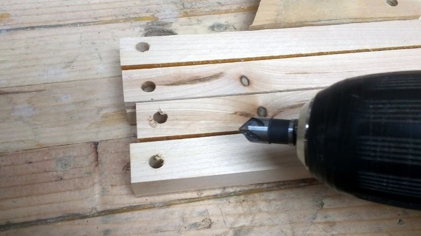
The first set of compounds that the author made using his system of ratios, he could not use, since they were not entirely correct.
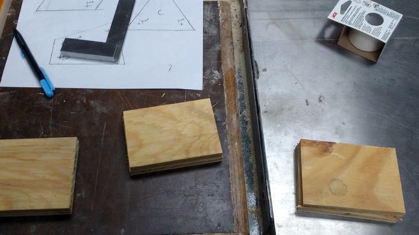
The reason they had to be redone was because the “knees” did not tighten very tightly. After redesigning, they still didn’t lie, but were already close enough to each other.
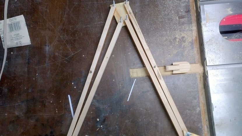
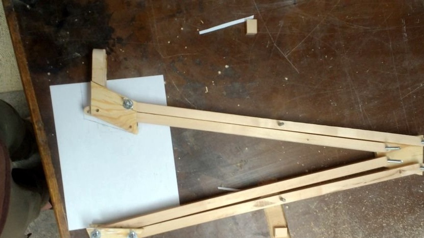
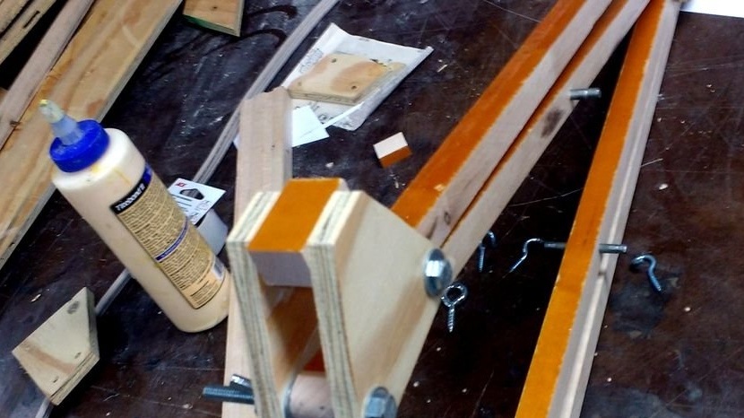
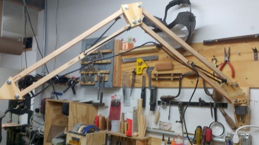
Step Four: Rack Assembly
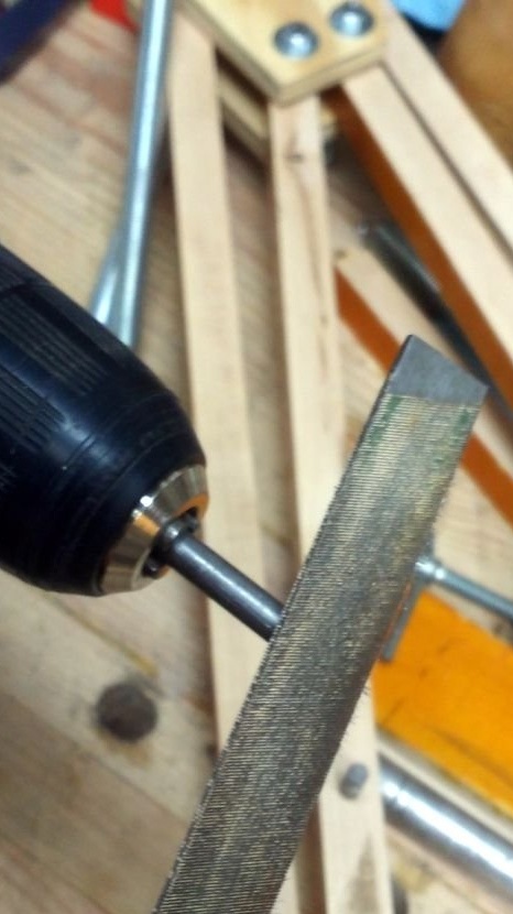
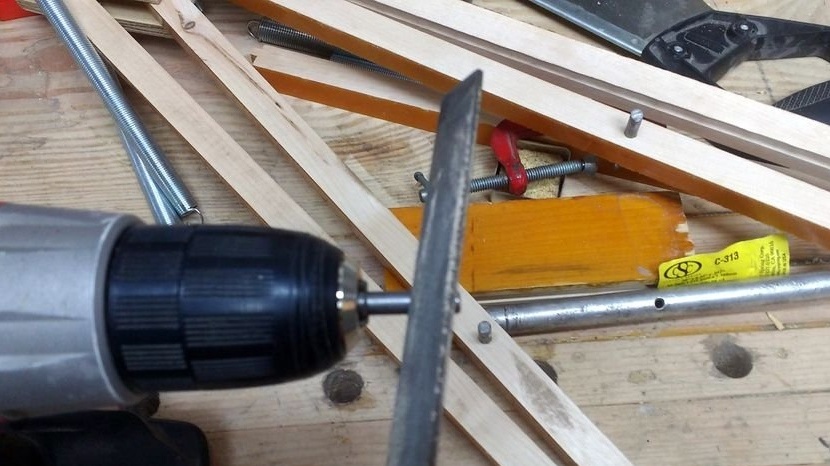
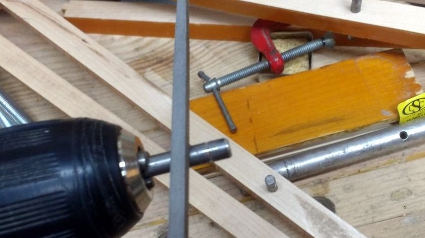
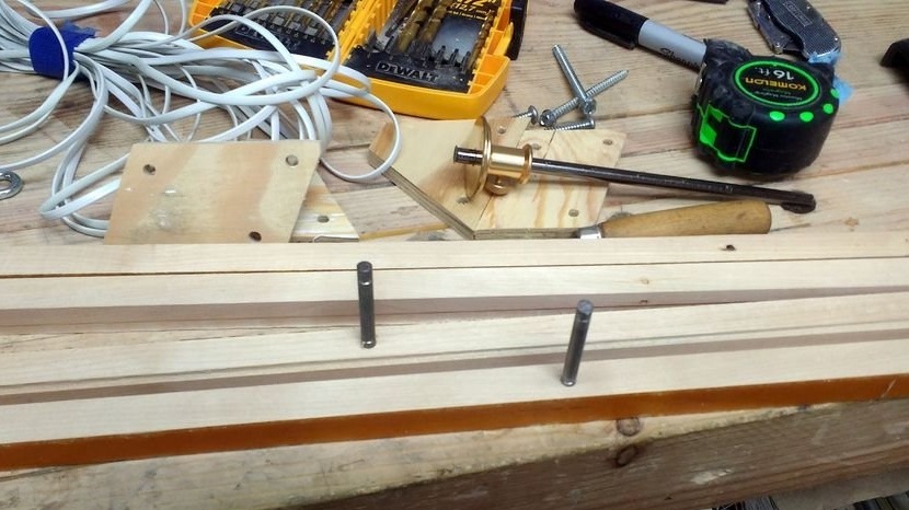
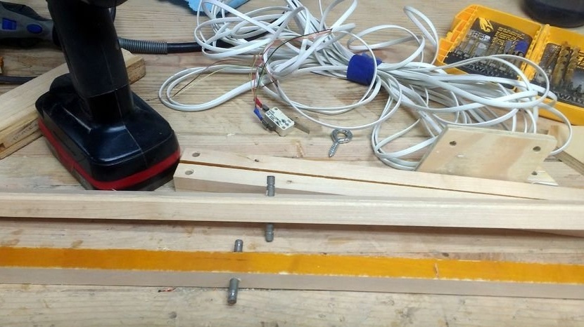
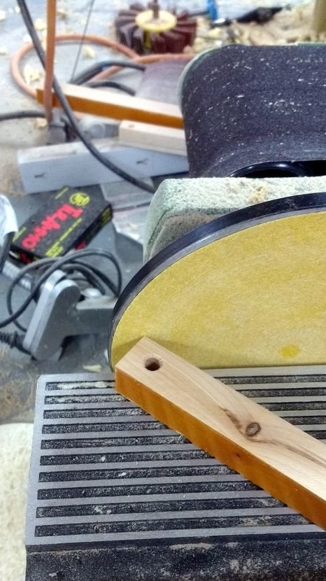
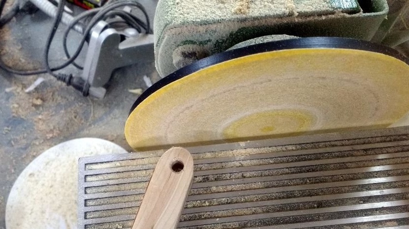
4 parts were cut from a 6 mm mild steel rod. 2 parts - 25 mm and 2 parts 50 mm. Then the ends of the studs were rounded with a file and a drill.
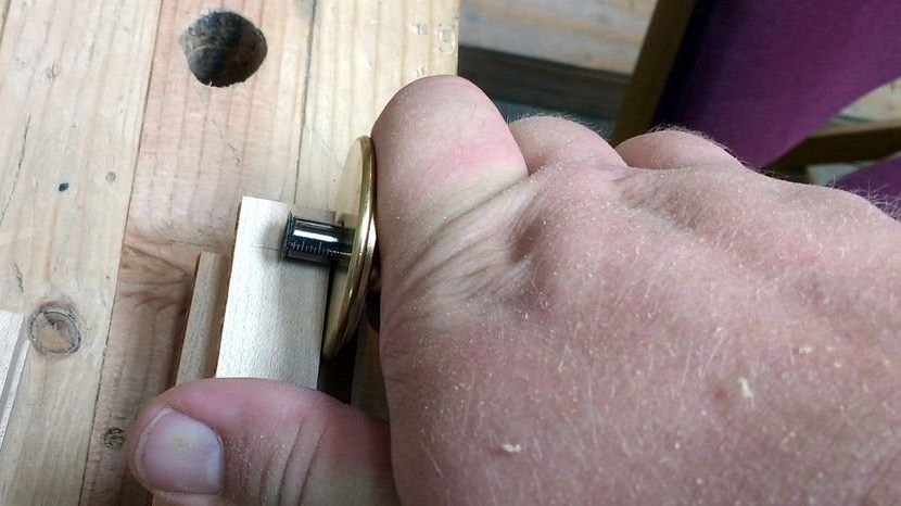
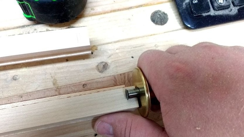
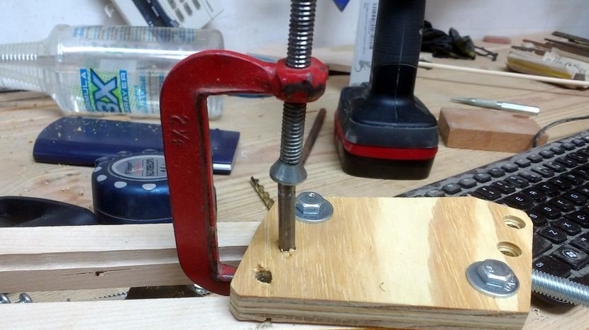
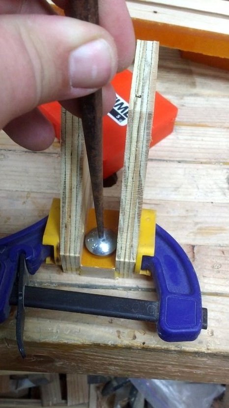
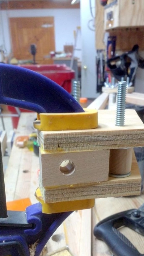
50 mm studs were inserted into the “knees” with holes in the middle, and 25 mm studs were inserted into the base of the axle. When installing the studs in place, a small clamp was used to firmly press the parts to each other on a rotary base.
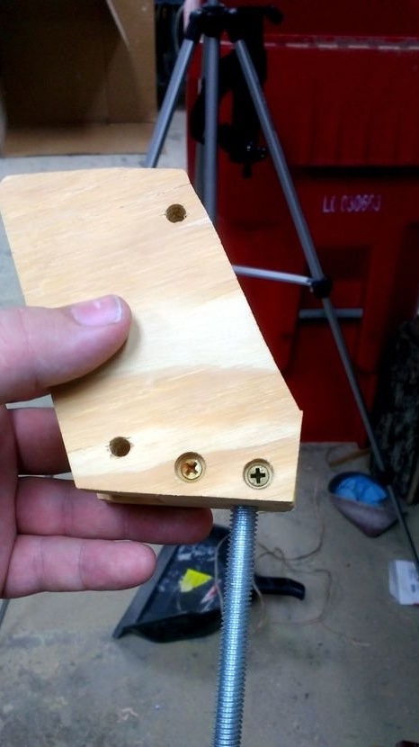
Two small wooden blocks were also made, sized so that they fit between the end of the triangle and the base of the hinge. The bars were glued into place. At the base of the hinge, the bars were reinforced with screws. 9 mm were also drilled. Hinge axis holes.
Step Five: Elastic Rubber Return
First, metal springs were tested as a return mechanism. But the author could not get them to work. Therefore, twenty mini gum was bought.
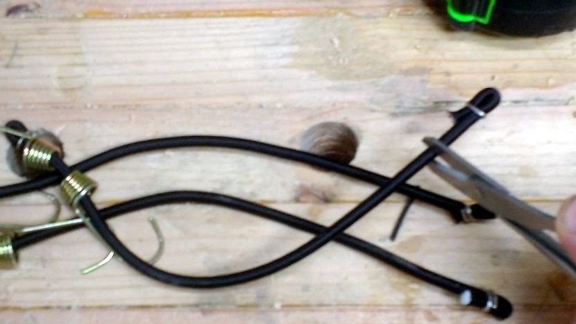
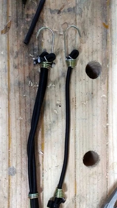
As a result of the experiments, it was found out that 3 gum on each side is required for the lower “knees”. However, the gum had to be shortened by about 25 mm. Otherwise they would fall.
To make the appearance of the structure more neat, the author changed the location of the landing hooks so that it was possible to pass three elastic bands through one hook and hold everything in place with stretched elastic bands.
On the upper "knee" it was required only 2 elastic bands on each side, and they did not need to be shortened. Therefore, one hook was used, two elastic bands for each side.
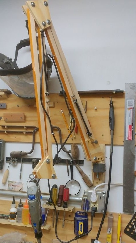
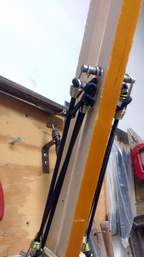
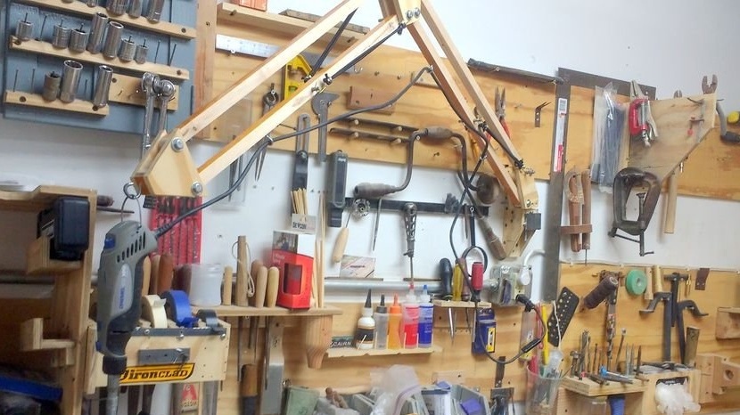
As a result, holes were drilled in the “knees”, into which several hooks were screwed. A power cord was pulled through these hooks.
The rack mount to the wall from the author was already available.