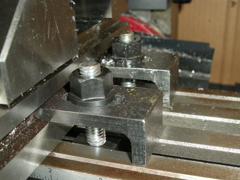
This is a guide to creating simple clamps to hold the milling vice on the milling table.
The milling vice shown in the photo above is a purchase option that the author of these clamps uses in his work. This small vise is a screwless tool with clamping grooves, which are sold by many online stores.
Step 1: Design
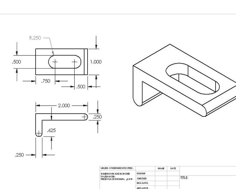
The lower surface of the clamping groove of the vise is approximately 14 mm above the table, and the upper surface of the clamping groove is approximately 7 mm above the lower surface.
The author makes clamps - a vice, like most masters, from some kind of scrap metal. Stock thickness 6 mm. Each side is about 50 mm in length (from the outer corner to the edge of the “foot”).
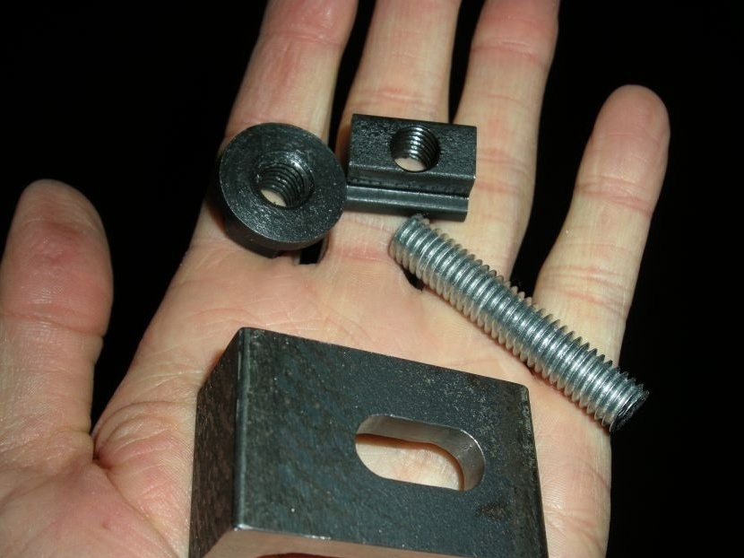
Additional materials that will be required in the manufacture of clamps are a T-nut, flange nut and stud, about 50 mm long with a 9 mm thread.
Attachments:
iron clamp bracket
Step 2: Rough Iron
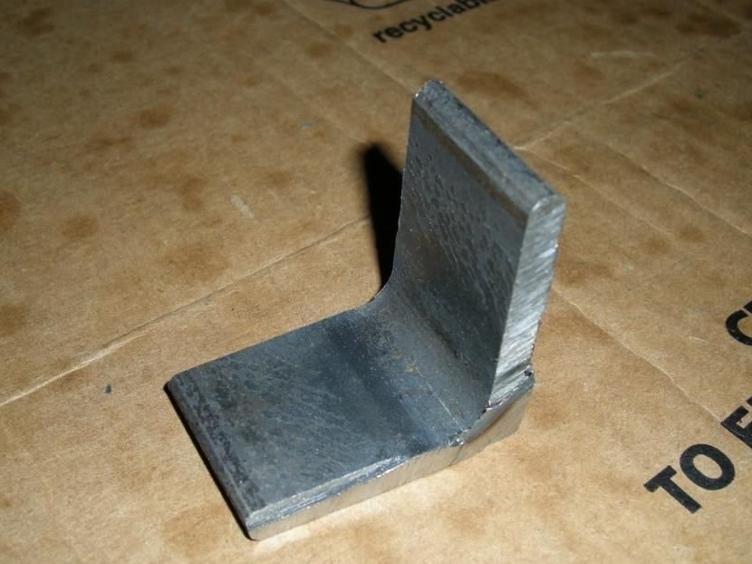
Using an abrasive cutting wheel on an angle grinder, the author cut off a corner of the right size. He cut himself well, but heated very much and therefore melted the plastic part of the table ...
In any case, the author managed to cut a piece about 25 mm wide from the iron corner. The exact size is not very important.
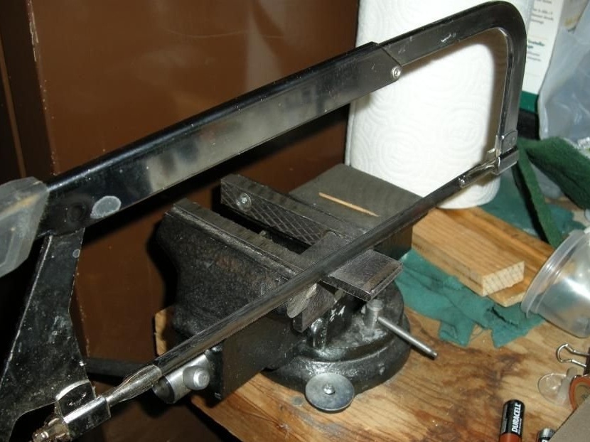
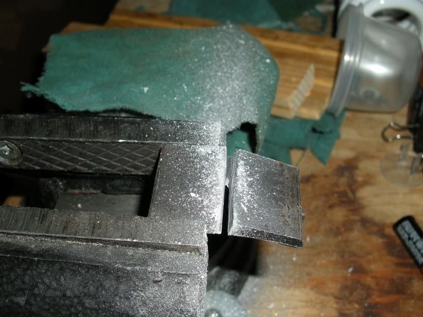
Then he cut off a small part of one long “leg” of this corner. A clamp will be made from the resulting corner. The author learned a lesson with a grinder and a plastic table and made this cut with a hacksaw for metal.
Step 3: Clean Long Edges
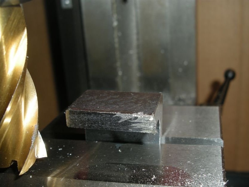
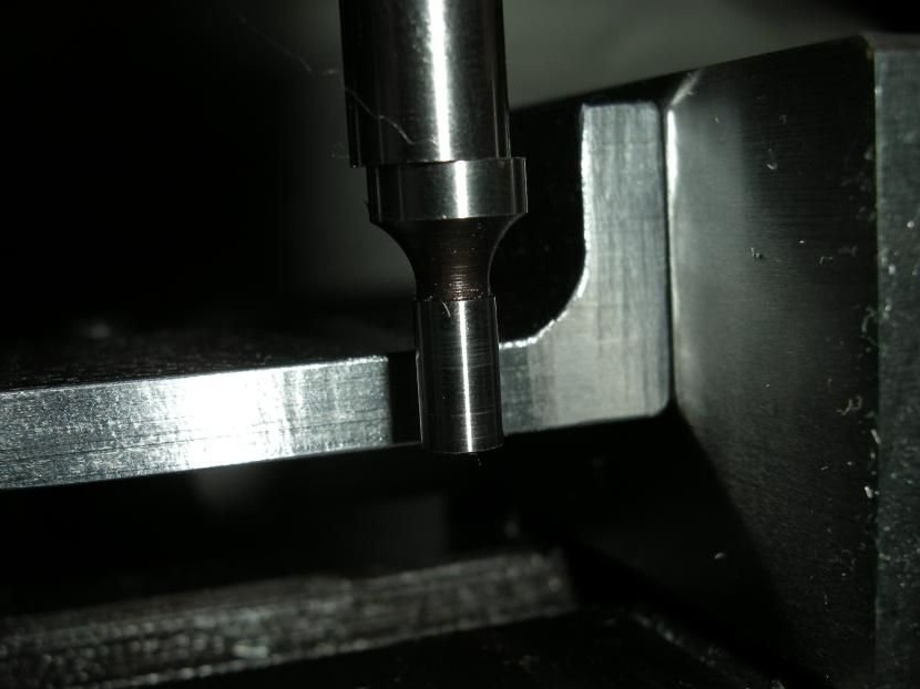
The author installed an iron corner in a milling vice and milled smooth edges along the entire length, neatly and evenly (and even a little in size, although this measurement is not very important).
The figures show the installation of a vice for milling two ends of a corner. The rounded long end of the corner fits into the horizontal V-groove in the movable jaw of the vice. The edge that he mills sticks out 6 mm. from the edge of a vise. This installation was quite safe.
Visually evaluating the workpiece in order to find the site on the corner that was most protruding, the author carefully touched the cutter at this point. Then he began to make passages for cutting metal in the Y-axis direction, from front to back, so each pass was performed in the usual milling mode (now he refrains from milling when lifting). Each pass cleared about 0.25 mm. material on any protruding parts of the workpiece. In the end, he cut the entire surface of the workpiece, and then made a 0.125 mm finish cut. At this corner milling was completed.
He used a 19 mm 4-channel milling machine, rotating at a speed of about 800 rpm. The feed rate was probably around 5 or 7 per minute. The depth of cut (each cut) was about 0.25 mm. Sometimes, during cutting, the author sprayed the WD-40 onto the cutter and workpiece.
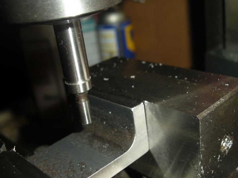
To mill the second long side, the author turned the workpiece upside down (as shown in the second figure). The location of the V-groove in the vise and the length of the short shelf allow this to be done.
Step 4: Mill the end of the short corner shelf
Then the author milled the short part of the future clamp, the part that will rest on the milling table. This operation helped to clean the support part of the corner and thereby set the working height for the clamp. This is perhaps the most important dimension, but even here there is room for some correction.
The author clamped the “long shelf of the corner” of the workpiece in a vise, trying to clamp the straight part of the corner, and not near the corner, where the thickness changes upwards, so the corner is reinforced. He set a corner in the center of the vise to keep the force balanced and to avoid twisting the moving part of the vise.
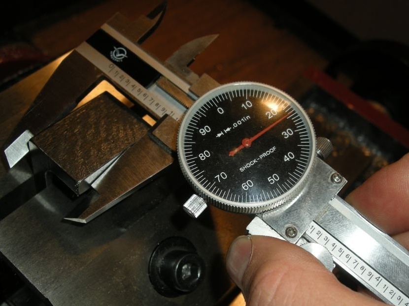
The desired length of the supporting part of the corner (according to the figure) is 21 mm.
First, he aligned the supporting part of the short flange of the corner, removing it with a cutter, in the same way as he aligned the long sides in step 3 (with the exception of the movement of the cutter along the X axis instead of Y).
As soon as the part became flat along the entire base of the supporting part, the author measured the height of the short shelf using a vernier caliper, having previously wiped the supporting surfaces with a rag so that the chips did not change the readings. This measurement showed how much material had to be removed. The author shot material with 0.25 mm sections until he reached approximately 0.5 mm. Then he again measured and made small sections until he reached an accuracy of 0.125 mm. The author stopped on these indicators.
Step 5: The corner part milling is finished
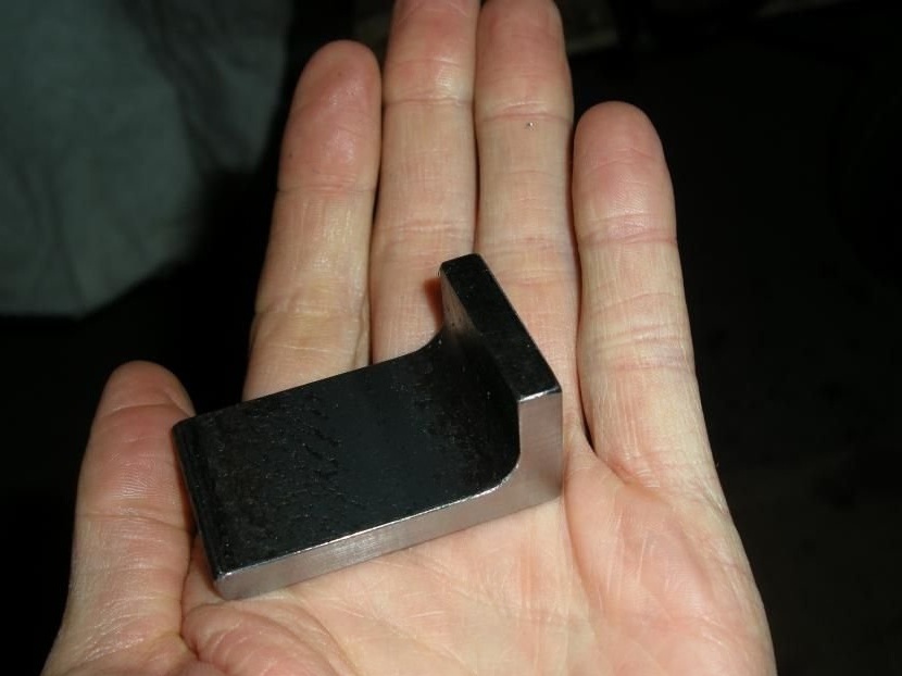
In this photo, all three faces of this part are smoothed and adjusted to the desired size.
Step 6: Setting up and installing a part for making a groove
The author did so.
It is very good when the workpiece is in the vise approximately in the center, because it gives uniform clamping, and not twisting, force on the movable part of the vise.
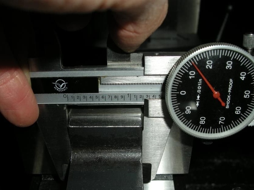
The author wants the cut in this part to be in the middle of the clamp, so he measured the actual width of the clamp, determined the edge and set the spindle in the center of the X axis of the clamp.
Here it is necessary to fix the guide of the X axis, since the movement will occur in the Y and Z axes.
Step 7: Locating the notch
Touch the “inside” of the corner and remember to compensate for the radius of the tool.
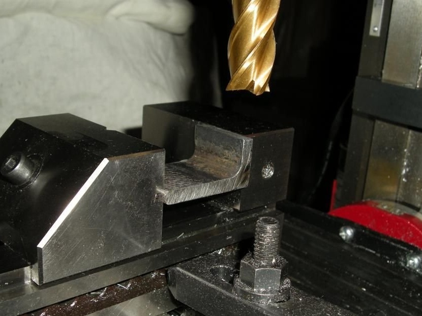
Step 8: Drilling Holes
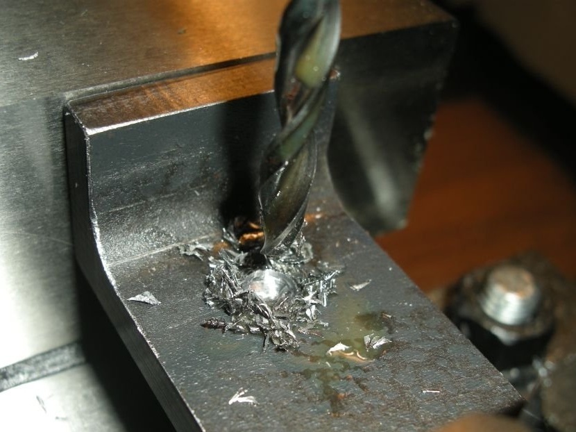
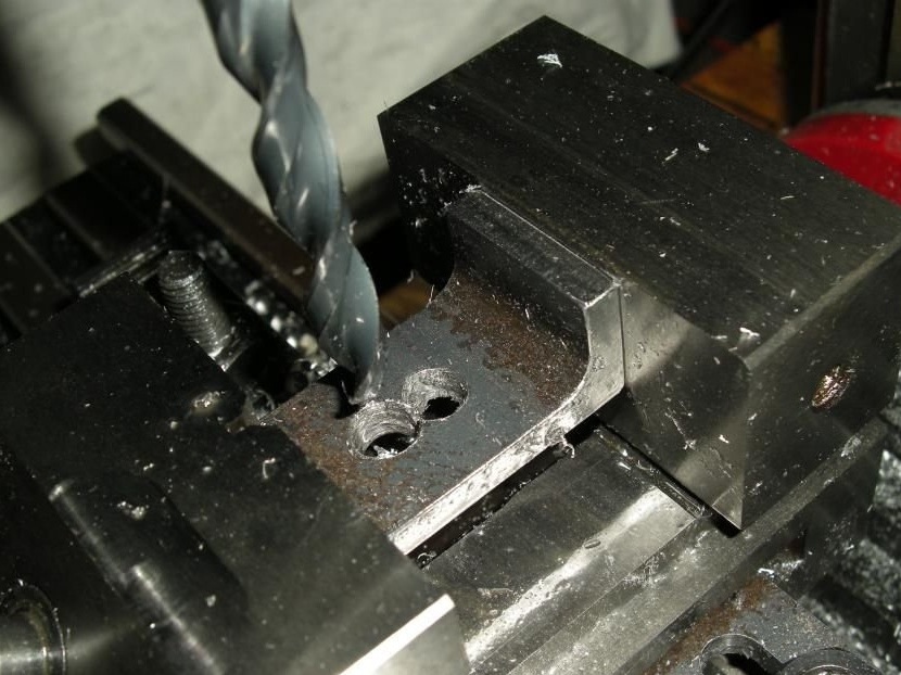
Drills are easier to sharpen than mills, so the author drilled holes to select most of the metal for the future groove. He started with a small drill (about 6 mm) for the initial hole, then increased it to 9 mm.
When the author finished drilling, in the middle of the clamp there were three holes with a diameter of 9 mm, the sides of which simply touched each other.
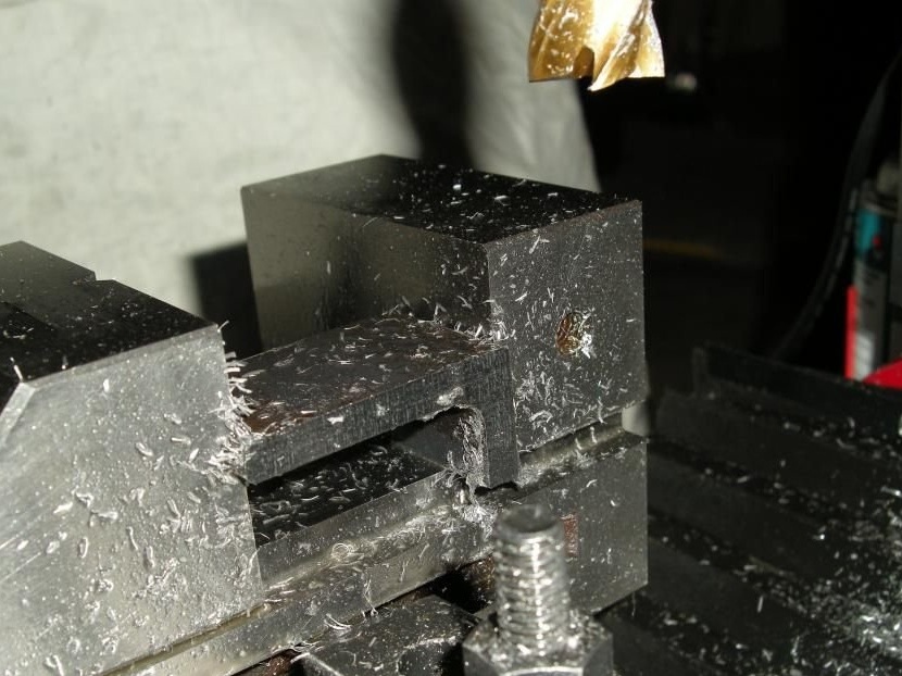
Step 9: Finish Groove Making
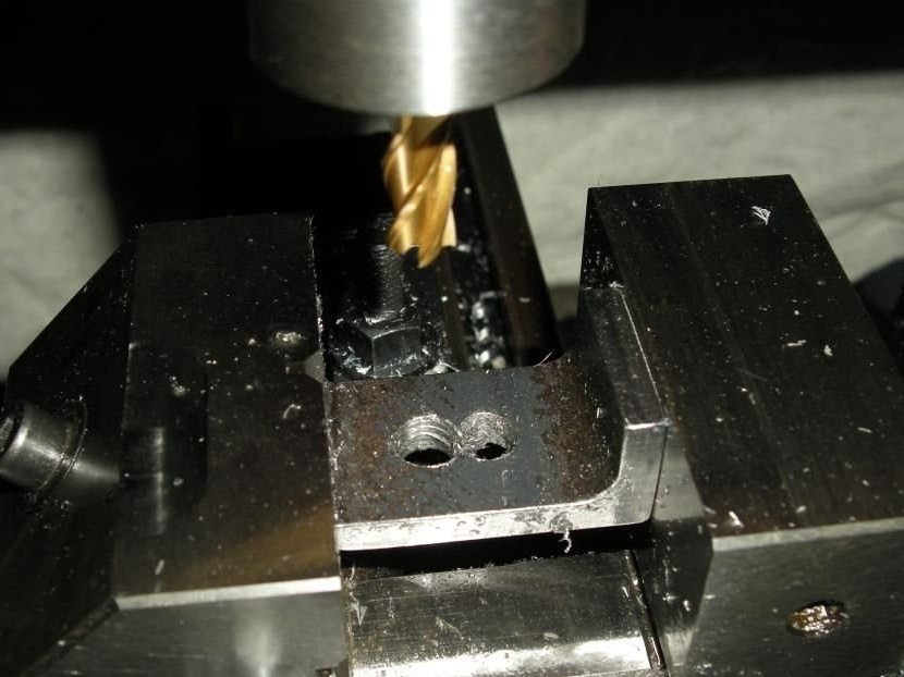
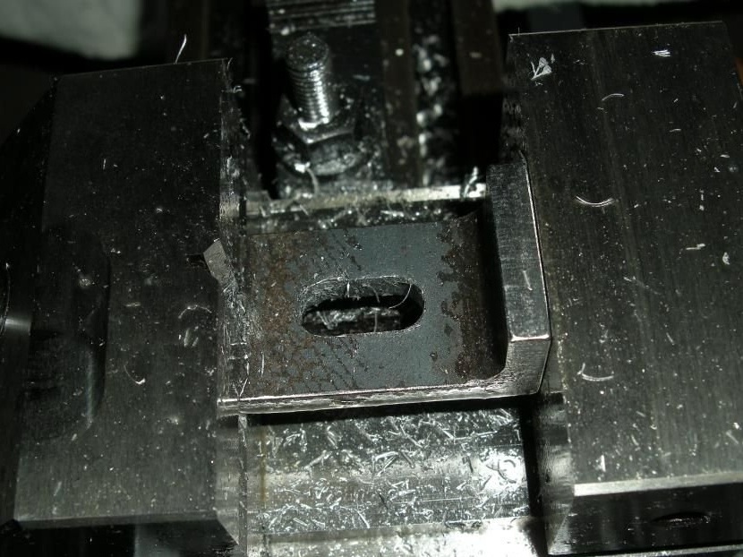
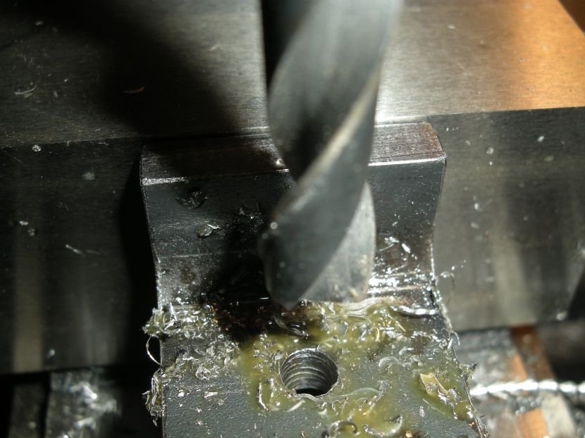
Then the author used a cutter with a diameter of 9 mm. To turn a series of holes into a real groove. Starting the spindle, he lowered the cutter (for cutting in the center) into the existing hole at one end of the groove, then moved it to the hole at the other end. He moved the milling cutter back and forth in the groove, going down about 1.250 mm or so for each pass, until he went all the way.
Then he expanded the slot by about 1,250 mm or so, moving the cutter in a spiral, cutting the entire wall of the slot with a cutting depth of about 0.25 mm.He cut the spiral clockwise to make routine milling.
(Note: in the photographs at this step, the author shows the corner where he tried to make a shorter groove with two holes pre-drilled. It works fine, although a longer groove is preferable.)
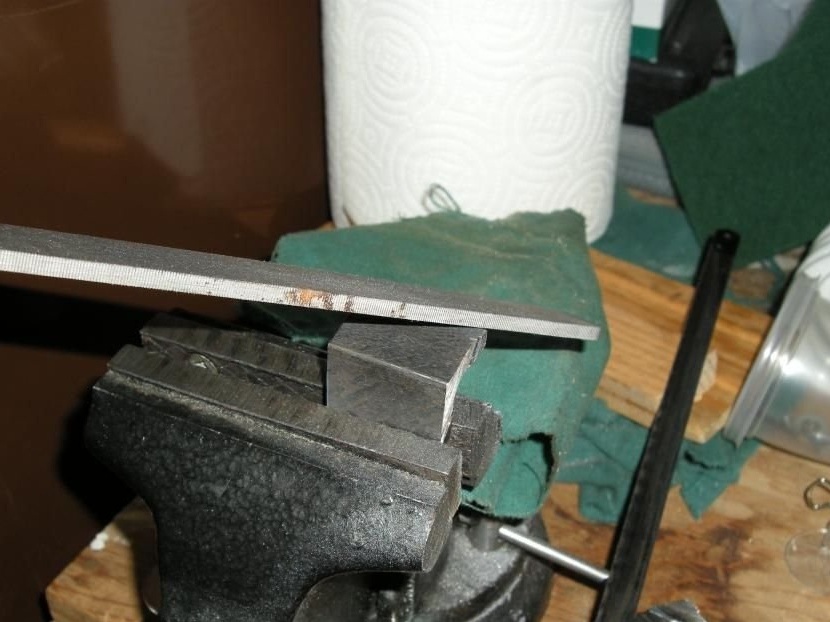
Step 10: Stud Preparation
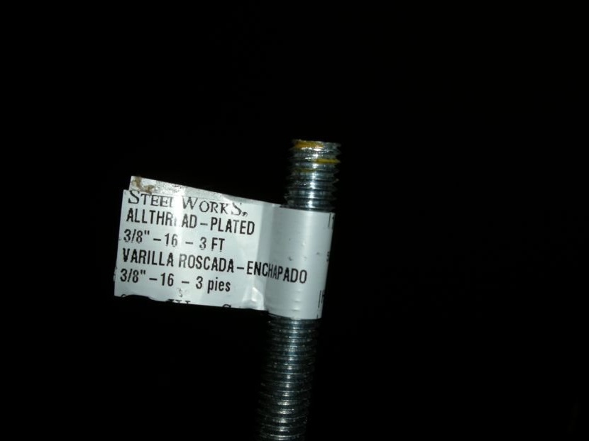
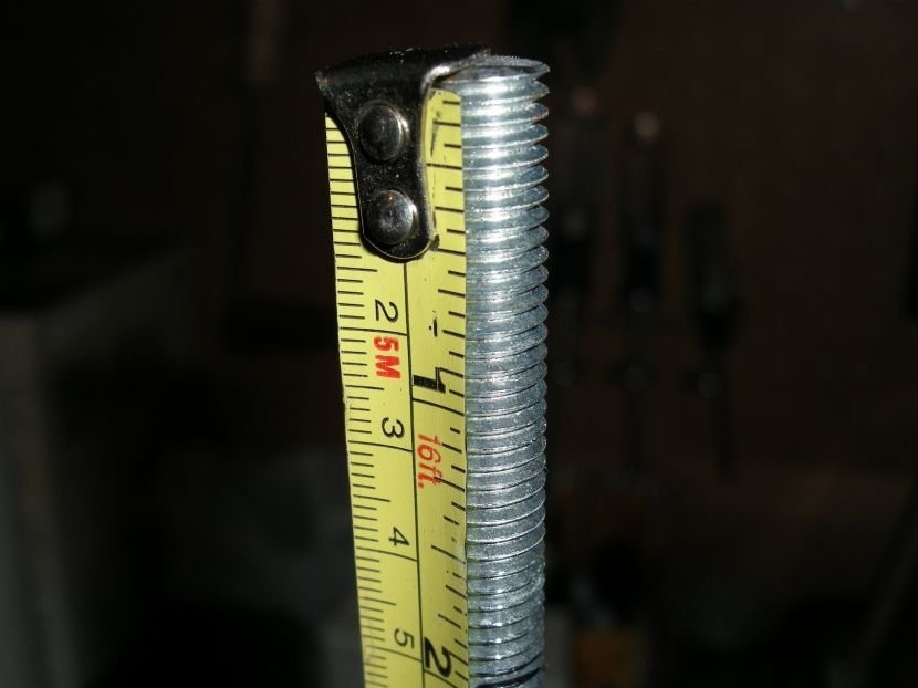
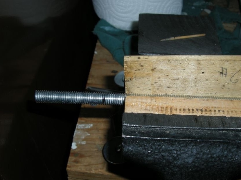
The author bought a stud with a thread of 9 mm.
He cut a piece of the required length from a hairpin with a hacksaw and cleaned the edges with a file.
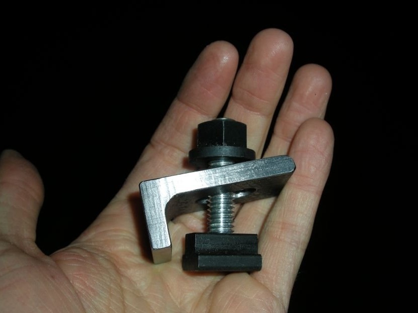
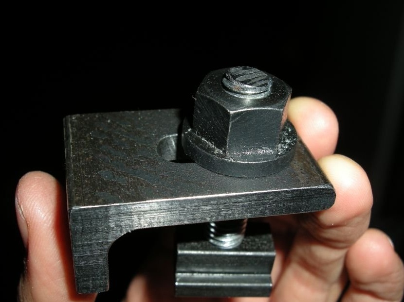
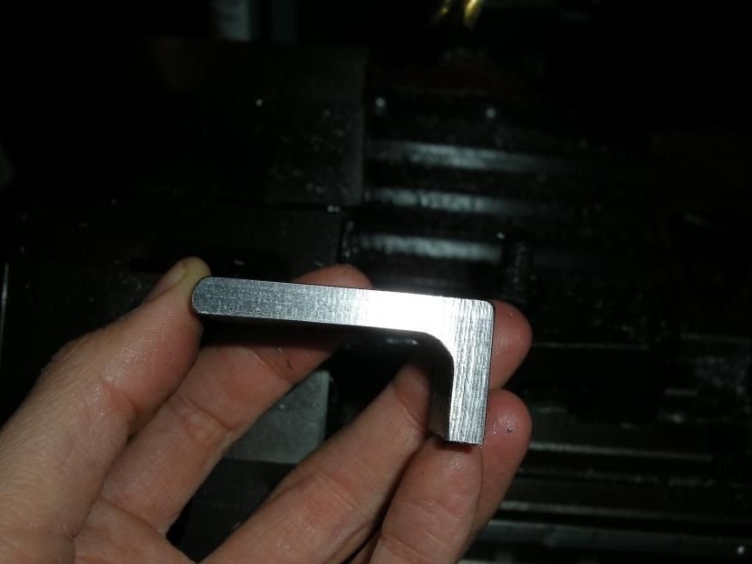
Step 11: the clamp is ready