
It's late at night, the author of this homemade worked on the project and found that the battery was running out in his electric multimeter.
He looked around everywhere, but never found where he could “get hold of” a 9 V. battery until morning. Deciding not to give up, he made the decision to make a quick and easy tester to check the integrity of the circuits.
Step One: Materials
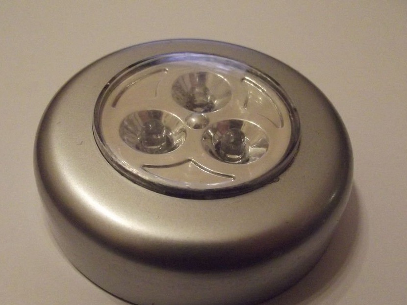
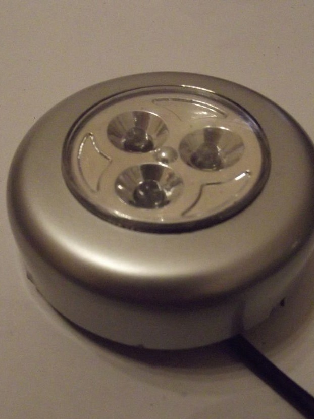
This homemade product is based on a compact battery-powered LED luminaire. This light comes with double-sided tape to mount it in a cabinet or under the stairs for extra light, but this light can also be adapted to other needs.
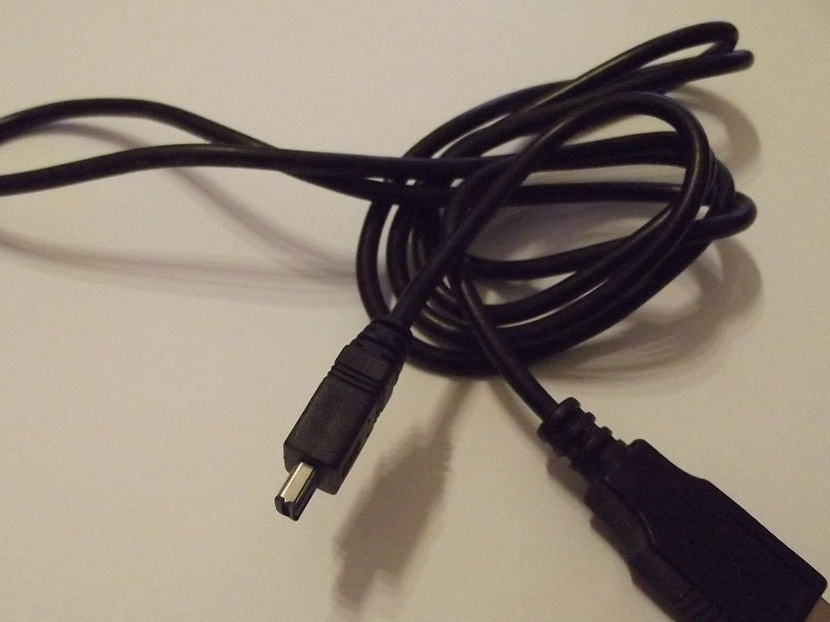
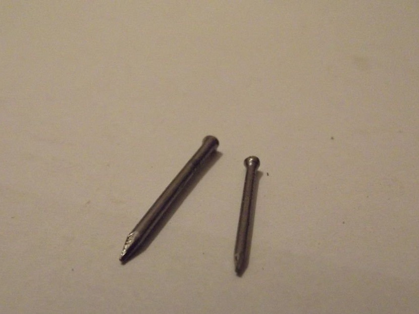
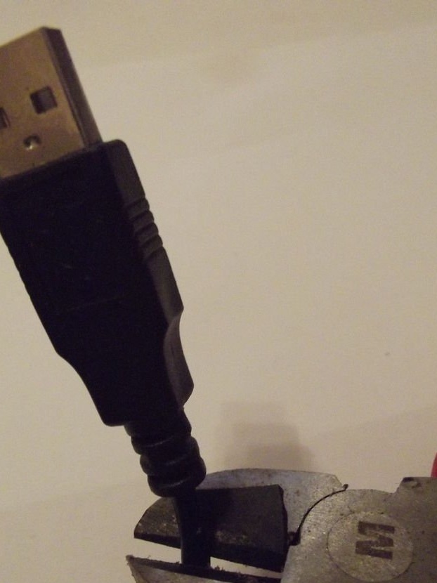
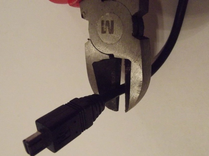
You will also need an old cable, for example from a charger for an old phone or the USB cable shown here. A USB cable may be the best option, as the wires inside the USB cable are individually insulated. The last thing you need is something instead of a probe to accurately place on the terminals that you need to check. All the author could find was 2 small pins that worked pretty well, but big nails would work just as well.
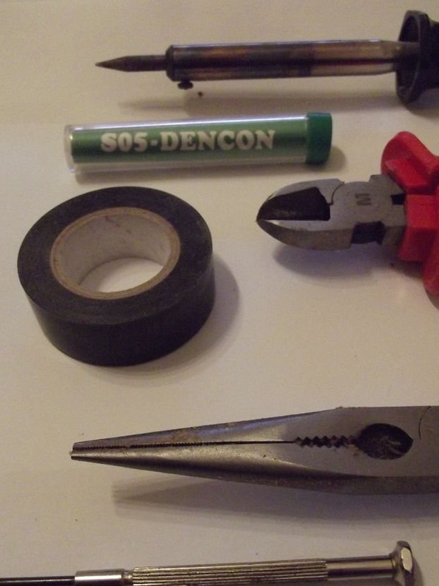
Tools that you will need for homemade:
- Small flat head screwdriver;
- Pliers with a long nose;
- Nippers;
- Electrical insulation tape;
- Solder;
- Soldering iron;
- Soldering flux;
Step Two: Disassembly
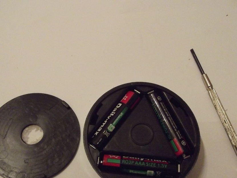
Using a flat-head screwdriver, remove the battery cover and remove the batteries.
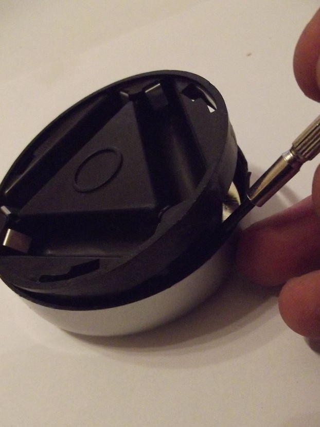
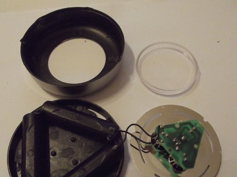
After the batteries are removed, a flat-head screwdriver must be clamped between the battery case and the outer case. With this position of the screwdriver, the case is quite easily disconnected, which exposes the circuit board with LEDs, as well as the wires connecting the battery case.
These wires connecting the battery case with the printed circuit board will be considered in the next step.
Step Three: Prepare
Now you should connect the soldering iron and let it warm up. In the meantime, it is heated, it is necessary to prepare the wires.
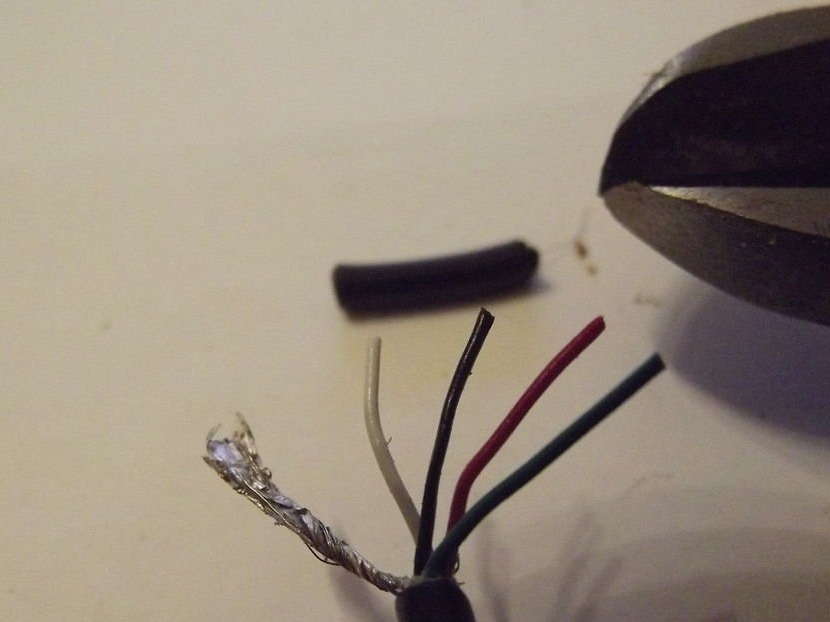
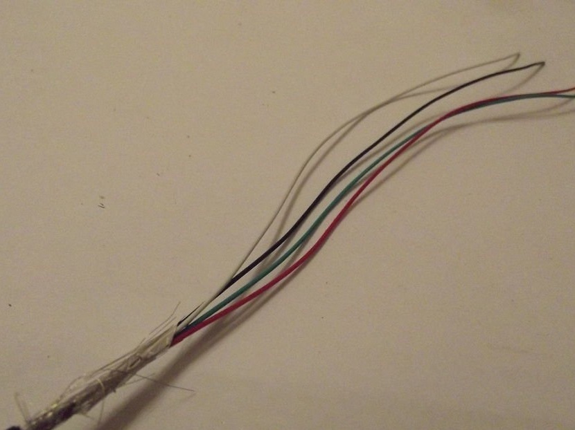
Use a pair of wire cutters to cut off the end of the charger of the telephone or USB cable, etc. This will expose a series of wires. In the USB cable you will find 4 insulated wires with different colors of insulation, covered with a metal screen. You will need to use only two wires. The author in this case chose red and green. The wires you use must be stripped with wire cutters to expose the copper wire.The remaining wires can be cut or simply bent.
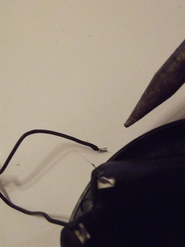
After the cable is prepared, the soldering iron should be heated to operating temperature. Now you need to hold the soldering iron on one of the wires soldered to one of the battery terminals until the solder melts and it becomes possible to remove the wire.
Step Four: Soldering the Cable
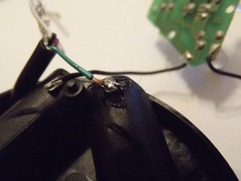
Now we can begin to solder the stripped wires into the circuit. This LED fixture had openings in the back, so the author first went through the prepared end of the cable. You may need to drill a hole in your fixture if you want to carefully close it.
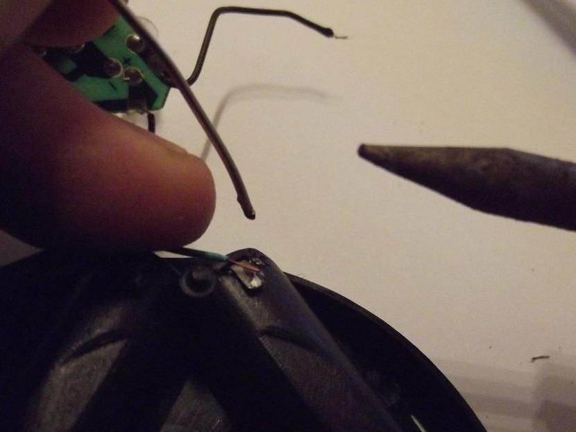
The author soldered the first wire to the battery terminal, from which the original wire was removed. At this stage, there may be a need for an “extra hand”. The author got out of this position by putting pliers on the cable to make it heavier and hold in place while he was soldering.
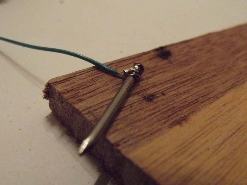
Connecting another wire would be a lot easier if there was a cable connector. The author used a piece of wood to solder a second stripped cable and a cable that was soldered from the battery terminal.
When the solder cools down, you can wrap the exposed cable slightly with insulating tape and reassemble the lamp housing.
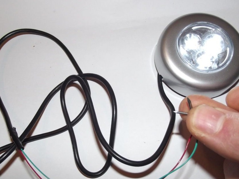
Step Five: Attaching Electrodes
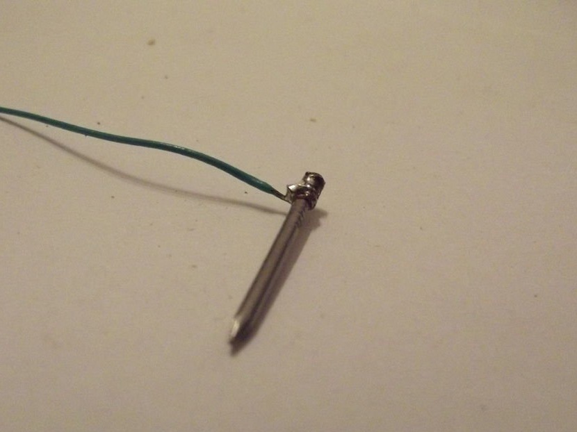
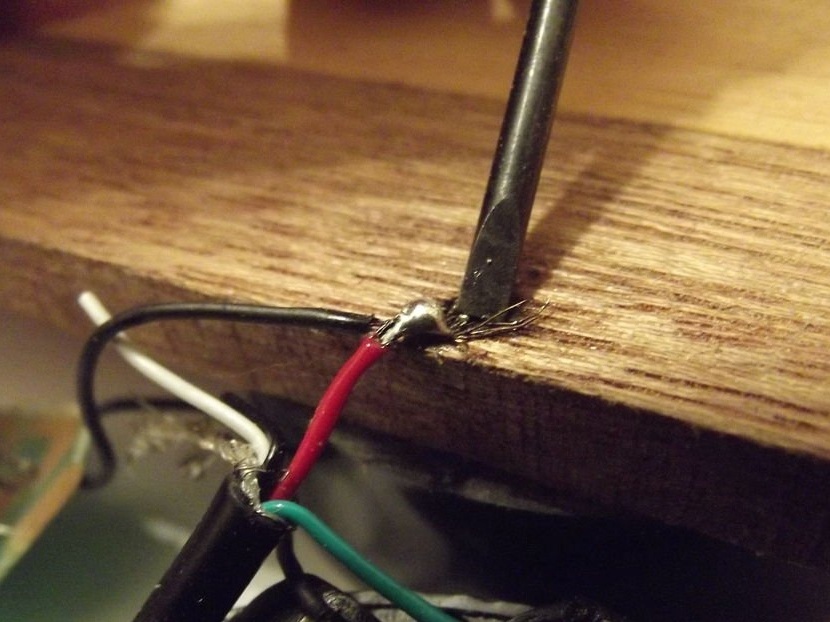
Cut the other end of the cable and strip the wires again. The second end requires the removal of a much larger part of the outer shell. The author used pliers to remove the general insulation after notching it. Since he used red and green wires, he could cut off the other two.
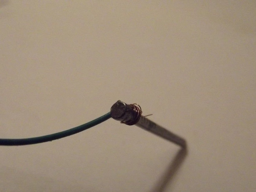
Soldering a future probe to the ends of the cable will be more difficult than soldering them to the battery terminals. Indeed, in order for the solder to solder 2 materials to be connected, their temperature must be the same. To keep the wire in place while the nail heats up, the author wrapped it several times around the nail head. This process was repeated for another wire.
Step Six: Everything Is Ready
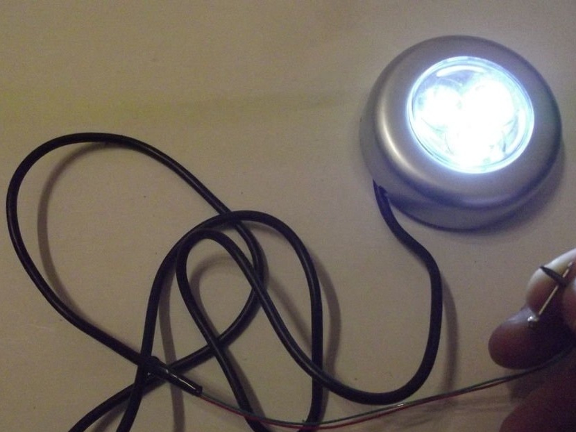
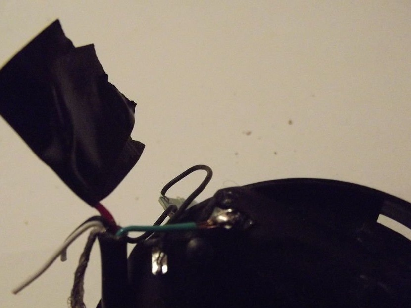
The last thing the author did was wrap an insulating tape around the end of the outer insulation.
This is a very simple and quick solution during the urgent need for a measuring device. Therefore, this homemade tool will be stored on a shelf, as the author is confident that it will come in handy again.