
This article is devoted to the creation of a test bench for the safe verification of the performance and characteristics of almost any pulse transformers for bridge and semi-bridge network switching power supplies.
This article is likely to be interesting for a narrow circle of ham enthusiasts, and for beginners who, after a successful start of their first flasher, want to assemble something complicated, such as a network switching power supply, the author strongly recommends not to repeat what you saw and in general, try not to work with the network energized, any mistake can cost you your life. The author of this homemade product is AKA KASYAN (YouTube channel "AKA KASYAN").

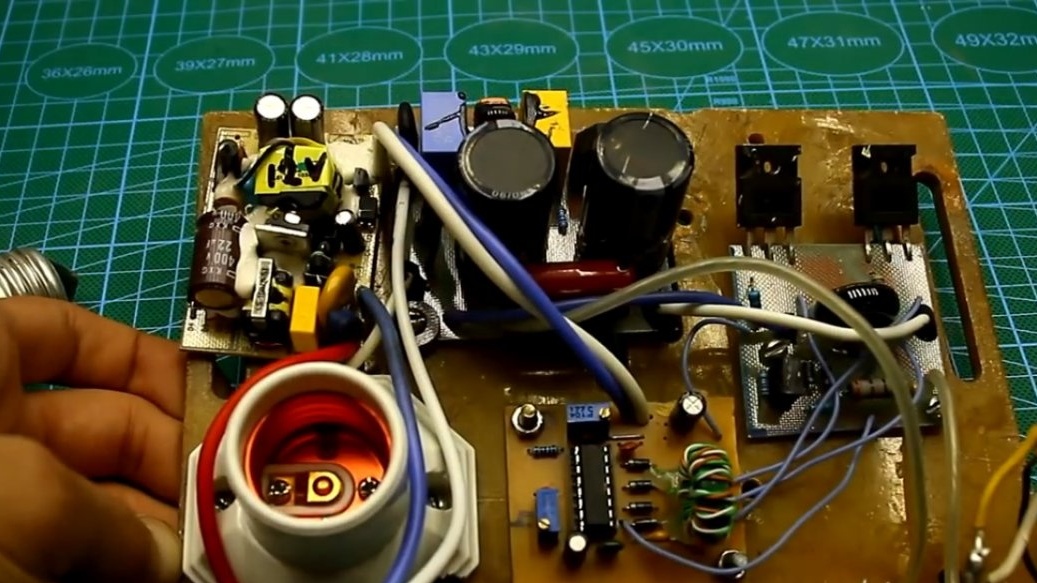
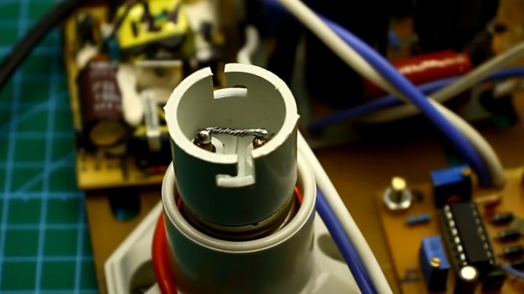
The test bench was made in haste, literally in a day or two. In fact, it is a power supply. There is the possibility of adjusting the operating frequency of the generator in the range of somewhere from 13 kHz to 205 kHz, and adjusting the duty cycle of the pulses, and therefore the power. The stand is quite safe, there is an adjustable system of protection against short circuits at the output of the transformer under test. At the input of the power source there is a cartridge for installing standard incandescent lamps with an e27 base to limit the input current of the source. This is an additional protection in case of an apocalypse or, if the main defense does not work.
For power testing, the lamp can be excluded from the circuit by screwing a short-circuited socle from the lamp into the cartridge.
Of course, it would be possible to put a conventional switch that would supply power to the circuit, bypassing the lamp, but the switch can accidentally be left on and result in broads. And so we 100% see what is installed in the base, lamp or jumper.
The low-voltage control circuit is galvanically completely isolated from the network part due to the fact that a separate low-power power supply is used to power the control circuit.
The base of the stand is thick fiberglass.
It provides very reliable insulation. Exclusively all wires that are used for installation have high-voltage heat-resistant silicone insulation. Firstly, it is safe, and secondly, during commissioning, the insulation of the wire will not suffer from accidental contact with a soldering iron.
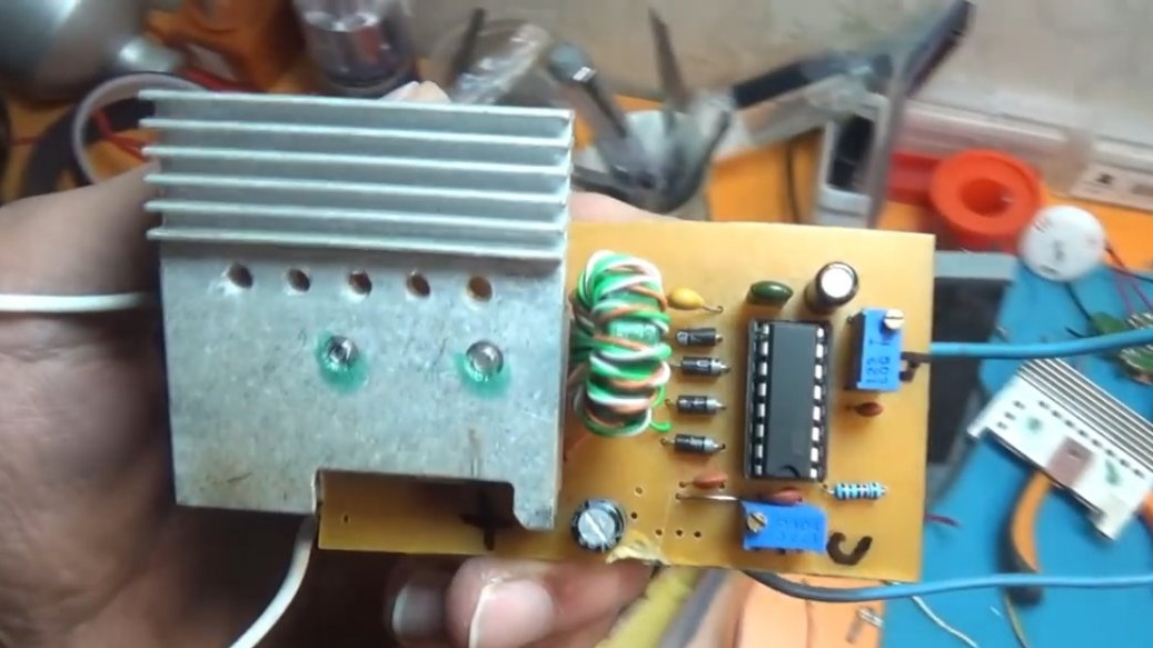
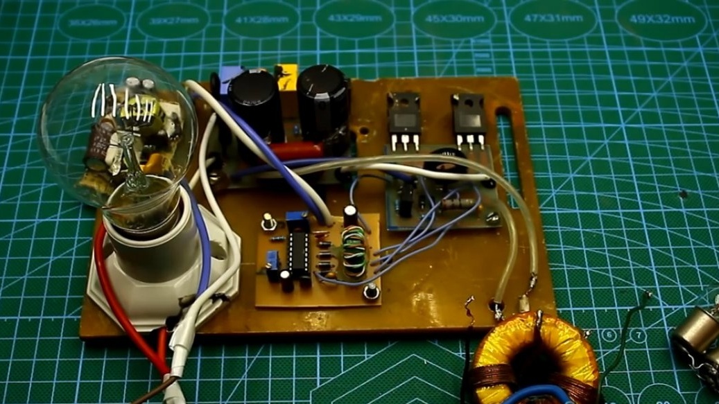
The stand consists of 4 main blocks:
1) surge protector with rectifier and half-bridge capacities;
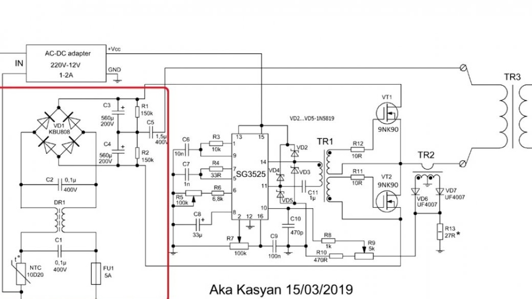
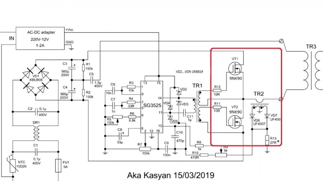
2) a power unit with transistors and a protection unit;
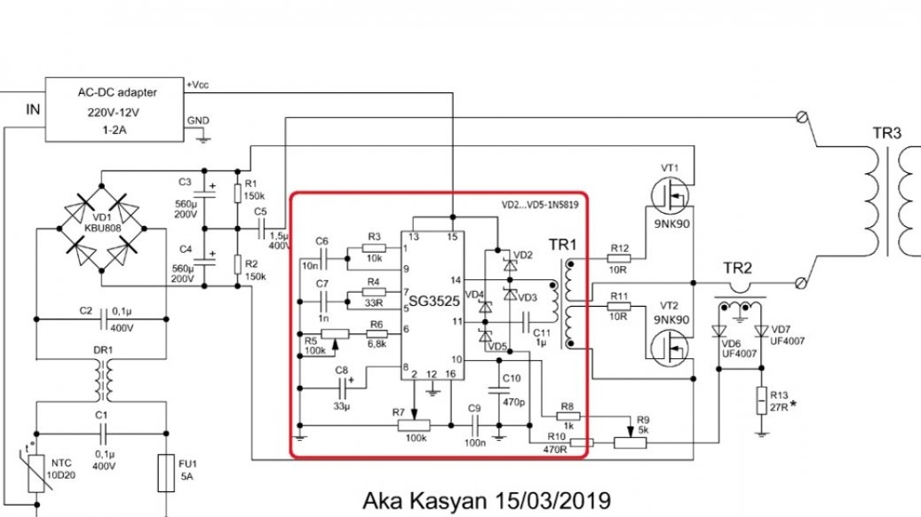
3) control scheme;
4) a separate power supply for powering the control circuit.
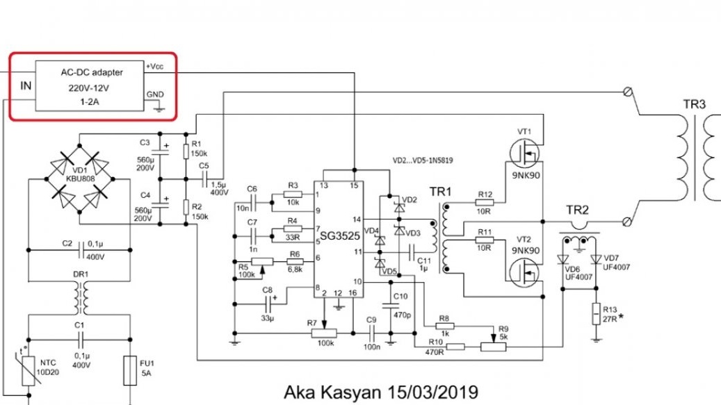
The stand is powered by a galvanic isolation system, so everything is extremely safe. The basis for this design was the generator board for a half-bridge induction heater.
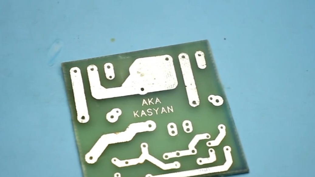
The boards themselves can be downloaded along with the general one.
With the connection of blocks of problems should not arise. If anything, then determine this photo:
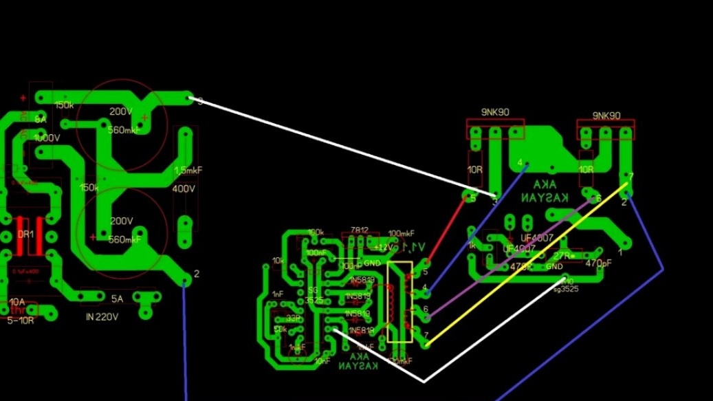
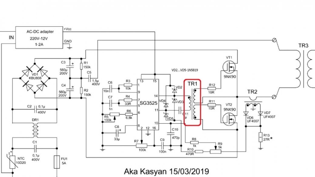
The control circuit includes a PWM controller and a matching transformer, which controls the power transistors and provides complete galvanic isolation of the control circuit from the high-voltage part.
And this is the complete circuit of the test bench for pulse transformers, the topology of the half-bridge circuit.

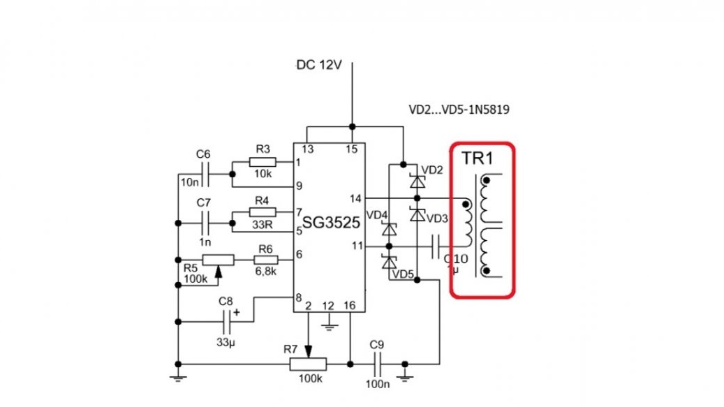
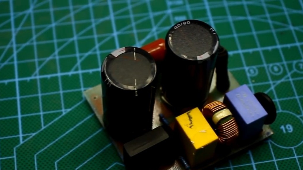
The power supply for the low-power 12-volt control circuit provides a current of 1.5-2A.
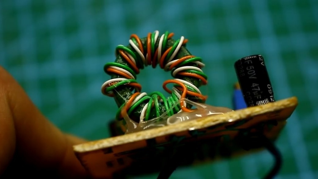
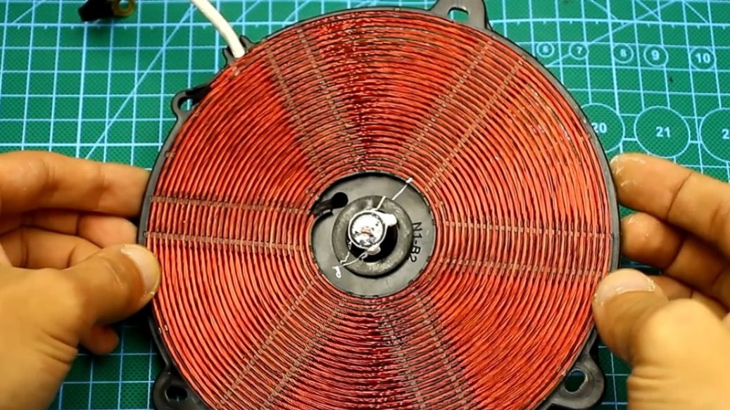
An external power supply will allow for a complete galvanic isolation of the control circuit from the networks, as mentioned at the beginning. Galvanic isolation transformer or TGR, wound on a ferrite ring. The author took the ring from a non-working computer power supply.
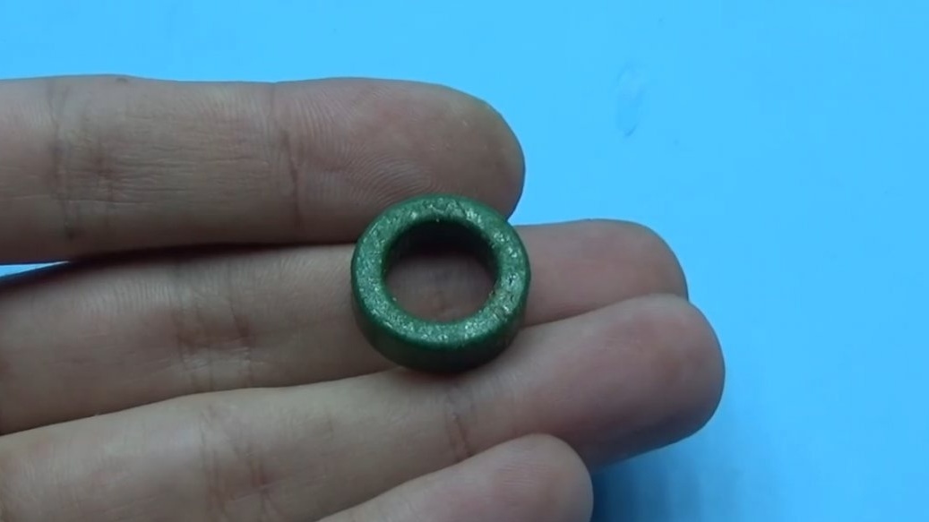
An input choke is wound on such rings. The yellow-white and other rings that stand at the exit as a group stabilization inductor will not work, the material is different, but we need ferrite with a magnetic permeability of 1500 to 3000, the dimensions of the core used by the author are now in front of you:

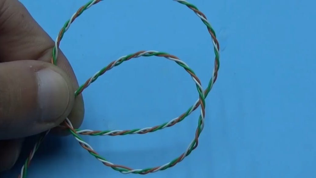
The transformer consists of 3 windings. The primary and two secondary windings are wound at once. The wire for winding all the windings is the same, can have a diameter of 0.3 to 0.5 mm. The primary winding consists of 20 turns, the secondary of 15 turns.
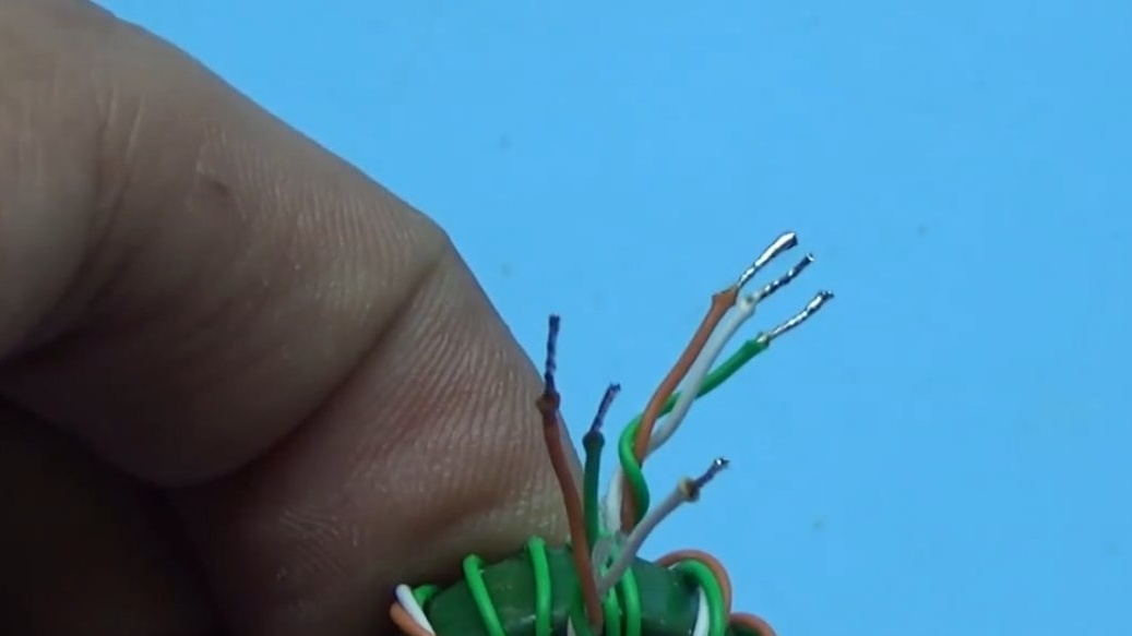
It is important when connecting to observe the beginning of all windings, they are indicated by dots both on the circuit and on the board. If you mix up the beginning and end of the windings, the circuit will not work.
The line filter, rectifier and half-bridge capacities are located on a separate board.
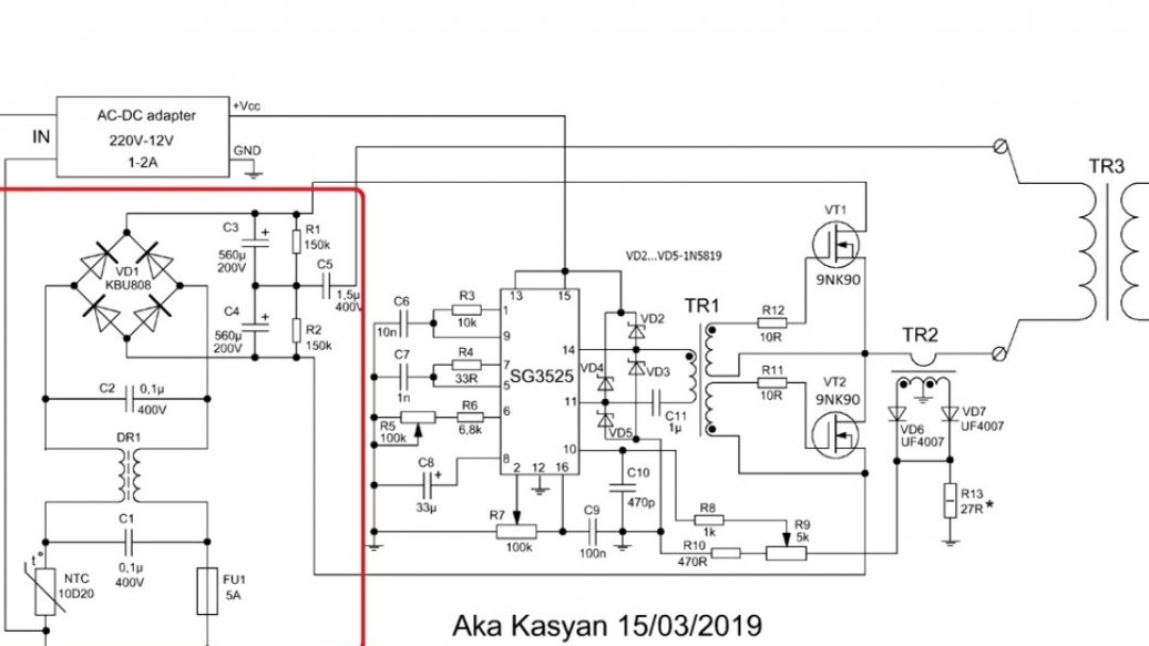
There is nothing special here, a pair of 200V 560 uF electrolytes, an 8A bridge and a fuse for every fireman. All this can be found in old computer power supplies.
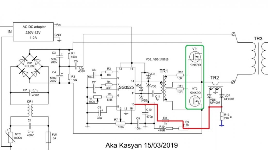
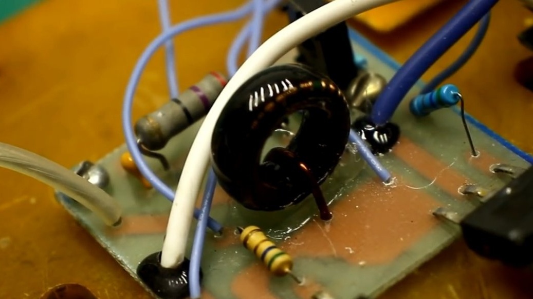
On the third board are power transistors with a short circuit protection system. The protection here is based on a current transformer and works as follows: the transformer has two windings, the primary is only 1 turn of a thick wire, which is connected in series with the primary winding of the test or power transformer, and the secondary winding is 100-120 turns with a tap from the middle.
The voltage from the secondary winding of the current transformer is rectified, then supplied to the load resistor. When we accidentally close the output of the transformer under test, a voltage drop forms on the same coil. This leads to an increase in voltage on the secondary winding of the current transformer, and, consequently, the voltage drop across the load resistor increases. If this drop is greater than somewhere around 2.5V, then the microcircuit is blocked, since this voltage is supplied directly to the input of the microcircuit protection. Then the keys of the internal driver are closed and, as a result, the power transistors of the power source are turned off.
A few words about the current transformer. First, the secondary winding is wound, it consists of two equal shoulders of 60 turns. The windings must be phased, connecting the beginning of the first with the end of the other, in the diagram the beginning is indicated by a dot. The wire for this winding must be taken with a diameter of 0.15 to 0.25 mm, it makes no more sense.
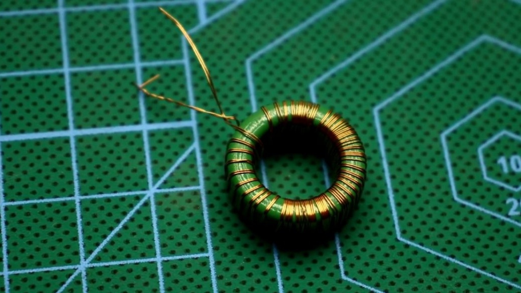
Windings, or rather shoulders, are wound at once to minimize the dispersion of their characteristics. The turns must be stretched along the entire ring. Try to wind gently without overlaps.
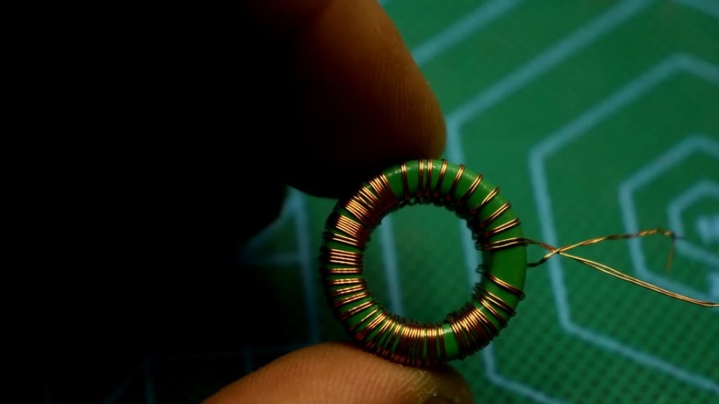
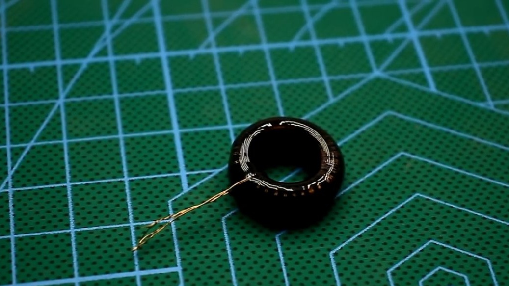
After winding, the winding is isolated with adhesive tape, electrical tape or something else, and it is best to pour with resin, beautifully and extremely reliably.
With the help of such a stand, you can find the optimal and maximum operating frequency of the core. If necessary, an incandescent lamp at the input can be excluded and load the transformer at full for thermal measurements and assessing the overall power of the cores.
The stand makes it possible to adjust the oscillatory circuits of induction heating systems and much more.
With the help of additional lotions, the device can be used as a powerful source of high-frequency alternating current with the ability to adjust power and frequency.
Thank you for attention. See you soon!
Video: