
Today we take a step one step higher in electronics, namely, we will assemble a synchronous rectifier. The device is not new, but not yet very popular.
The author of this homemade product is Roman (author of the YouTube channel "Open Frime TV").
As you know, in any power supply the output is a rectifier diode. Recently, Schottky diodes are widely used, since they have a lower voltage drop and, therefore, they heat less. But there is still heating, and at high powers it is impressive.
If you put an ultrafast diode, then the situation is even worse, since the voltage drop is larger, and from here one of the most important problems arises - these are radiators.
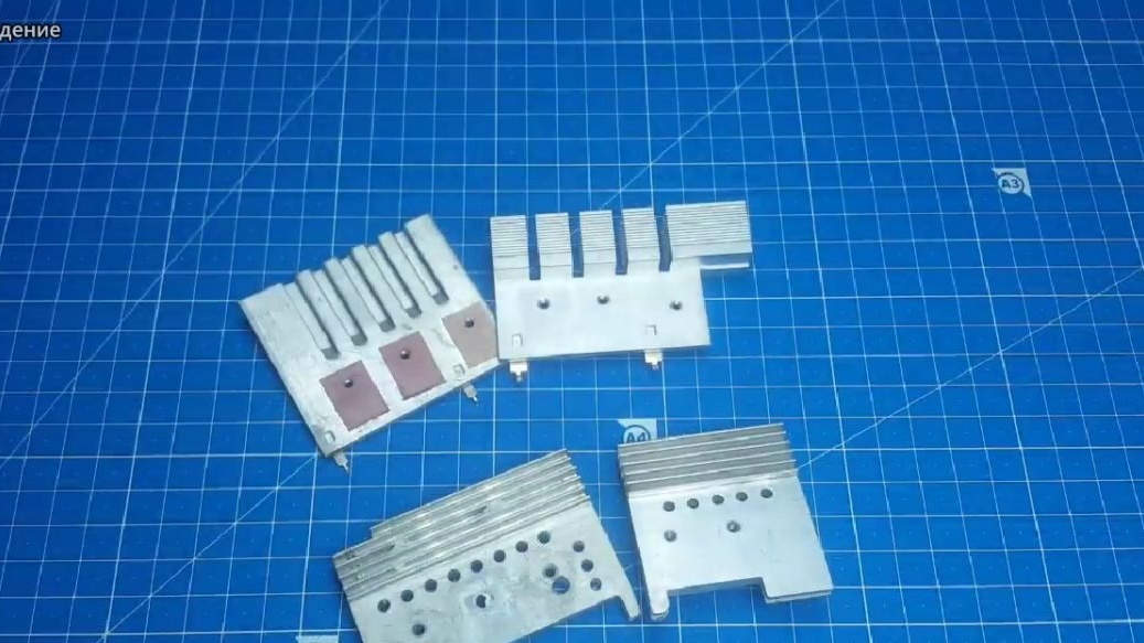
In a good way, you can’t set the high side and low side on one radiator, since a breakdown can occur and high voltage will get to the output. So you need to separate the hot and cold side on different radiators. But not everyone has the right amount of radiators to cool everything. And at high capacities one can not do without forced cooling.
Smart people began to think about this problem and found a simple way out - to use field-effect transistors instead of diodes.

Their open channel resistance is very small and, therefore, the current flowing through them will produce less heat. At first glance, everything is simple, but no. For correct operation, transistors need proper control. Here, smart people also worked and created microcircuits for controlling transistors in a synchronous rectifier.
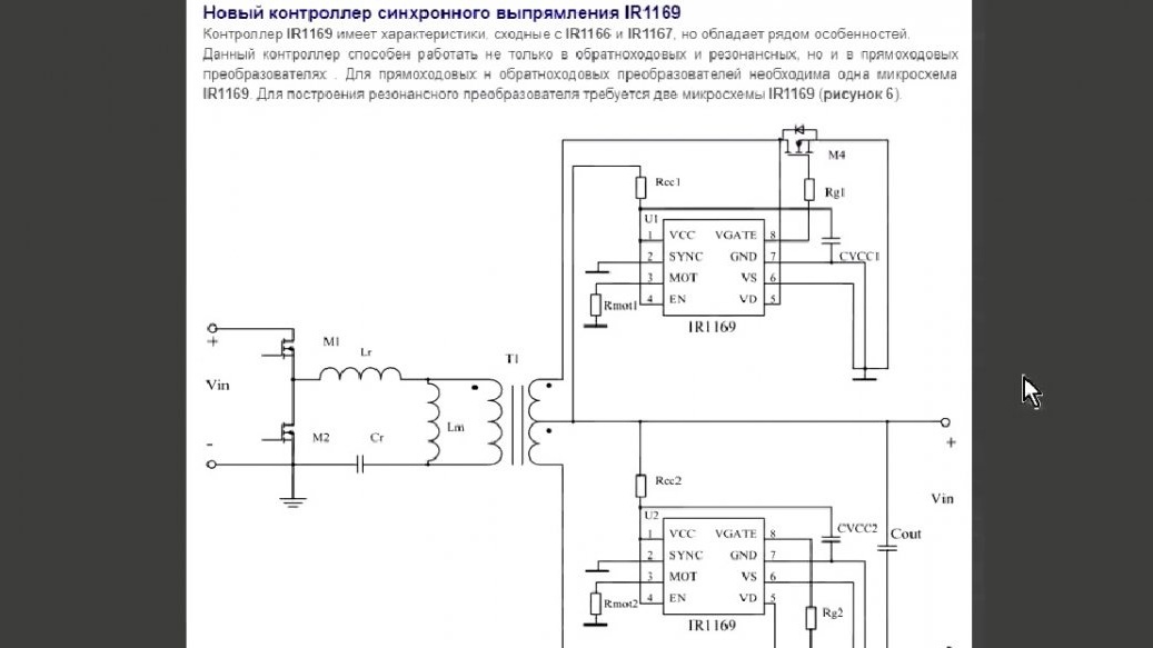
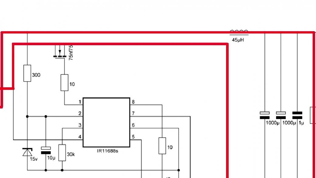
We just have to assemble the circuit and figure out how it works. The scheme itself is in front of you:
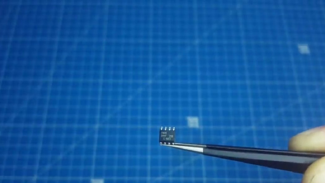
As you can see, there is nothing at all here. The rectifier chip is only in the smd package.
From this it turns out that the control scheme will not take up much space, and the efficiency will increase significantly. So, let's try to figure out how it works. The first thing that catches your eye is that the middle point will be a plus, and the side points will be a minus.
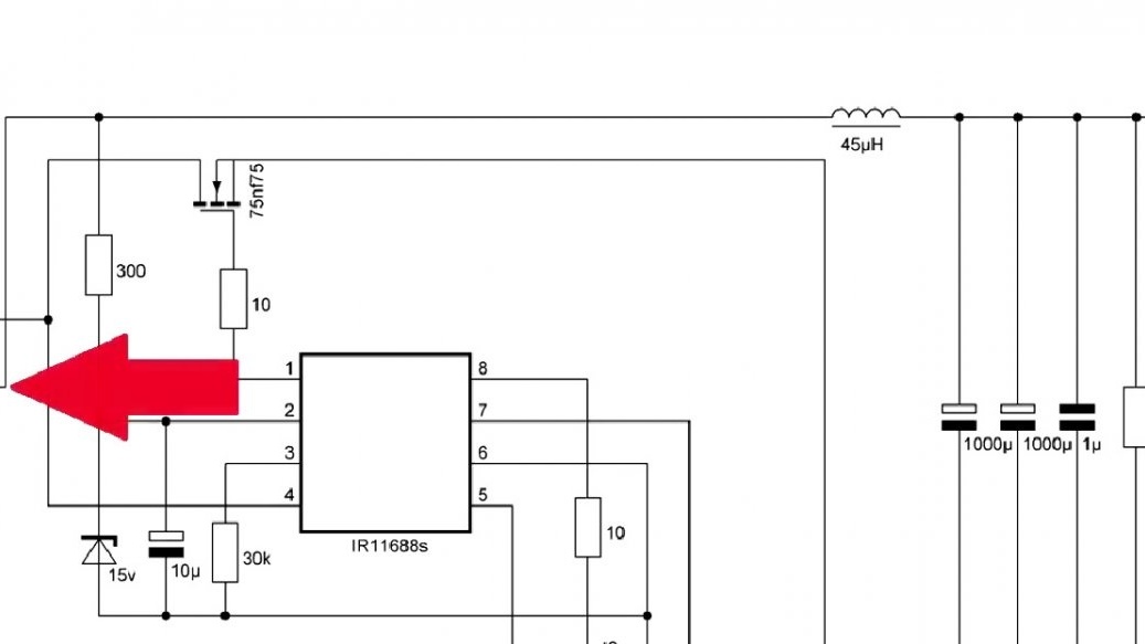
That's because transistors turn on in the opposite direction.
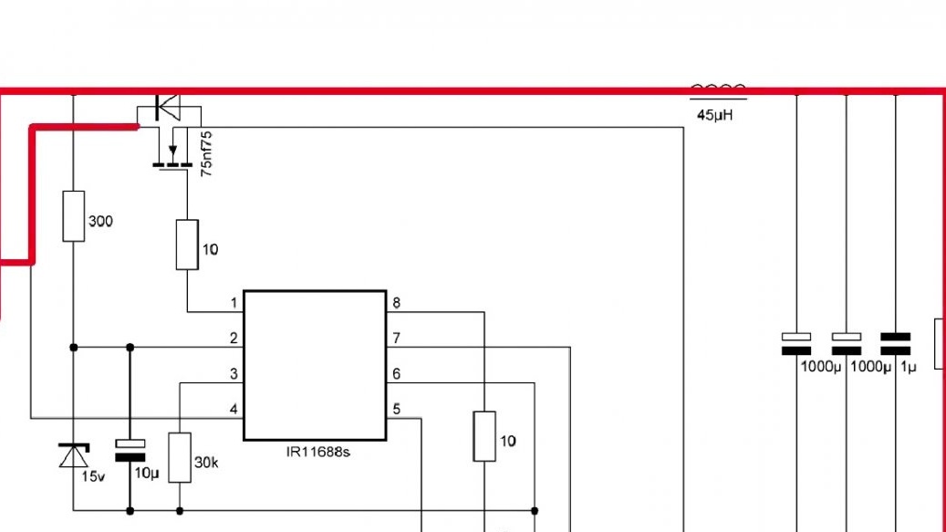
The rectifier works in this way: for example, during the first pulse we have such signs on the windings.

This chip monitors and opens the lower transistor.
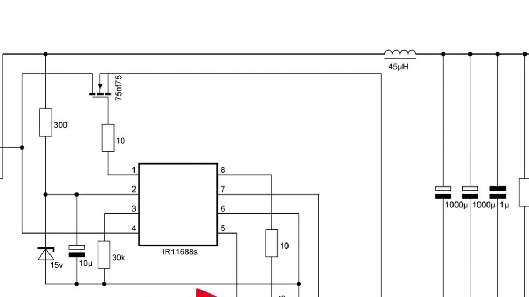
Current at this time flows along this circuit:
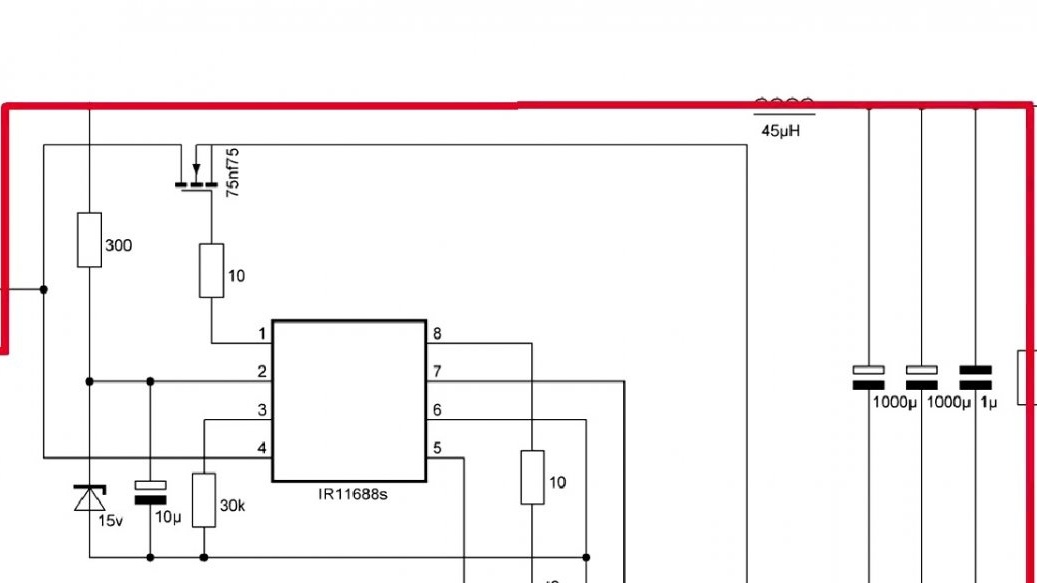
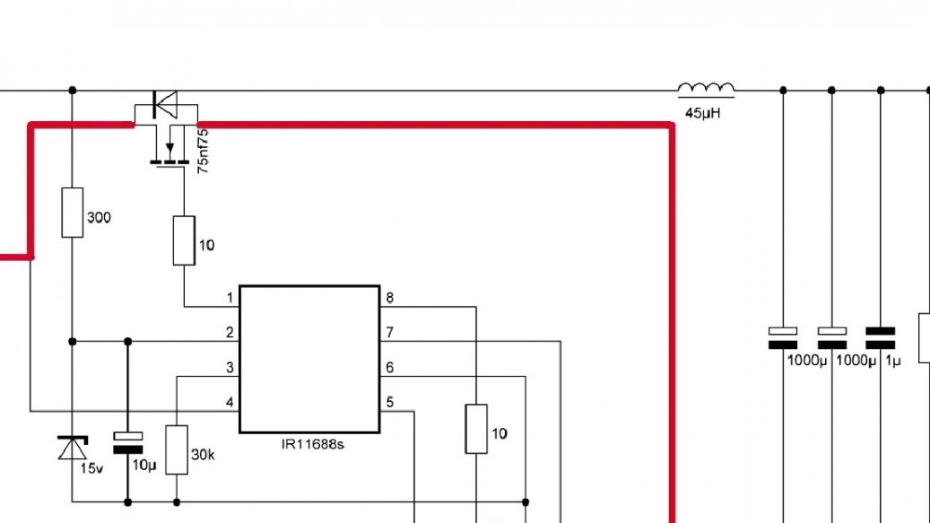
This is followed by a second impulse.
Now the upper transistor opens and passes current to the load.
Experienced electronics engineers will immediately remember the internal diode in the transistor, but if you look at the voltage signs again, it becomes clear why the transistor is turned on in the opposite direction.
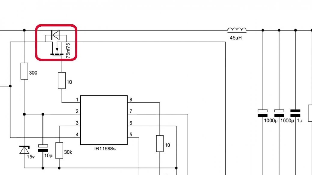
While one transistor is open, the second is supported by a high voltage and the diode a priori cannot pass current.
But each action has consequences, in our case this is manifested in the fact that two voltage amplitudes are applied to the transistor. As you understand it is bad. We learn more about this in real calculation.
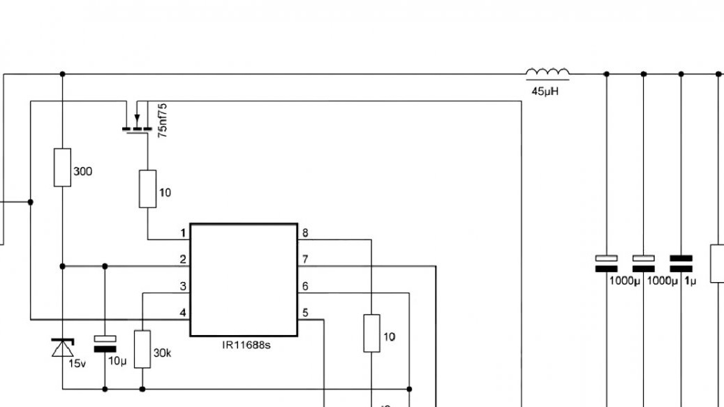
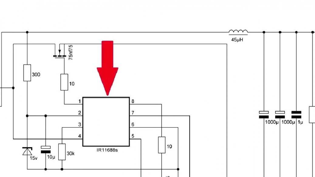
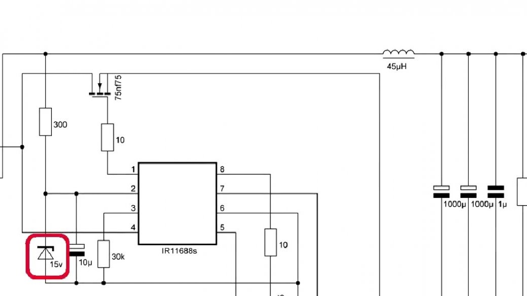
Now, as for the remaining elements of the circuit. A zener diode is needed to limit the power supply of the microcircuit, since it should not exceed 20V.
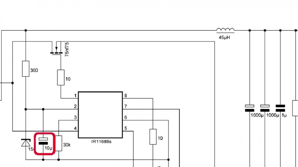
The capacitor smoothes the supply voltage of the chip.
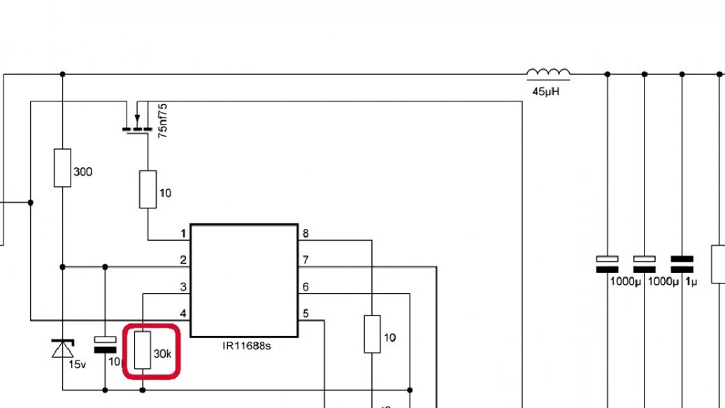
The resistor going to the ground can be selected in the range from 25 to 150 kOhm, it affects the speed of the opening of the transistor. The author chose a 30 kOhm resistor, which is enough.
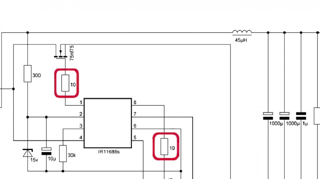
Also, the gate resistor affects the opening speed, its rating can be from 10 to 30 Ohms, you can expand the limit more, this is up to you.
To test the operability of this circuit, I had to draw a signet. This is a pure synchronous rectifier board. You can download the circuit and signet HERE.
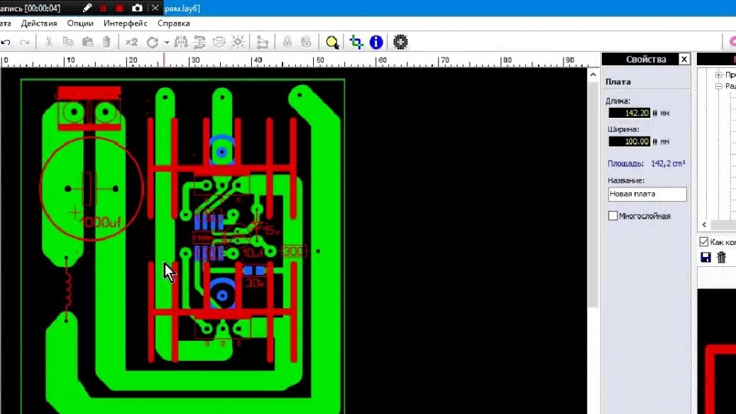
It can be built into any half-bridge power supply and forget about overheating of the output part. As you can see the signet turned out to be compact. The width of the power tracks is small, but as mentioned earlier, this is the layout.
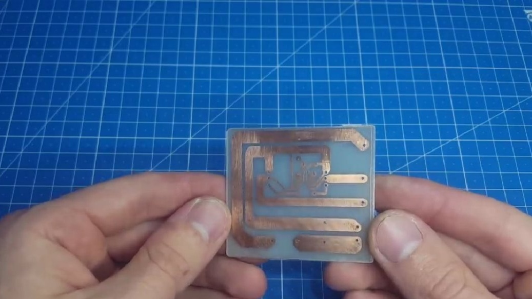
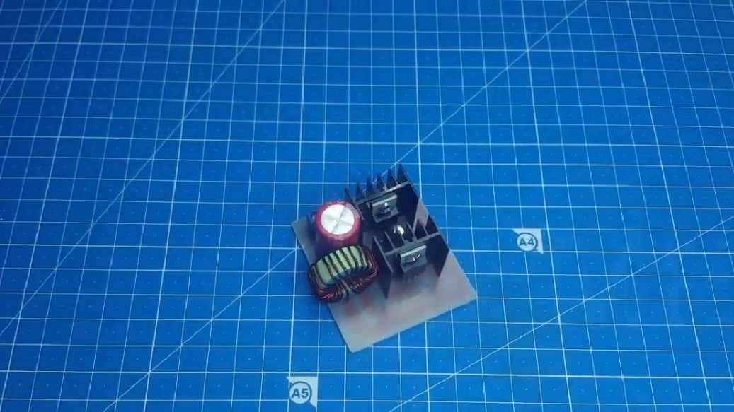
When the board has been etched, solder it. Difficulties can arise only with the microcircuit, but if you try, then everything will work out. As a result, we get such a beautiful device:
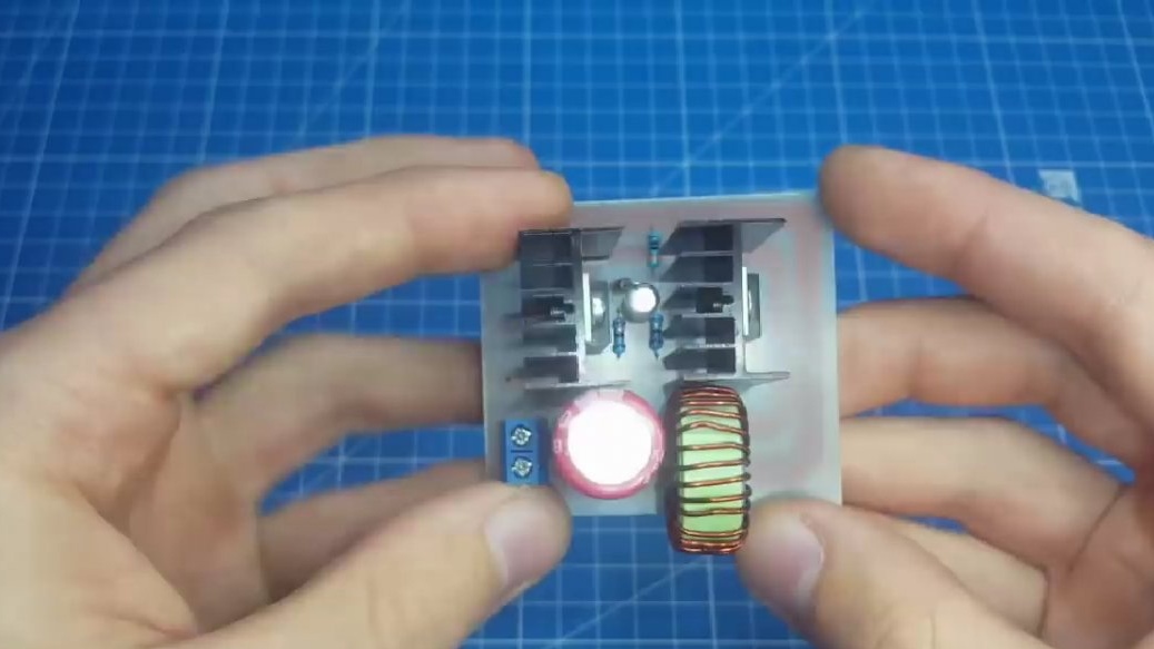
Now let's talk in more detail about the calculation. Since this is a trial version of the author, and he is not equipped with a master part, we will use an external transformer from some old project to start it. The main part here is IR2153. The output should receive about 24V.
The calculations of this block in front of you:
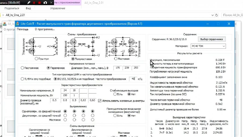
We are interested in such a parameter as the amplitude value of the secondary voltage, we have 28V. And now we multiply this value by 2, why, as mentioned above. And on the received voltage we need to choose a transistor. We go into the catalog of transistors of the radio market and begin to look at what is available.
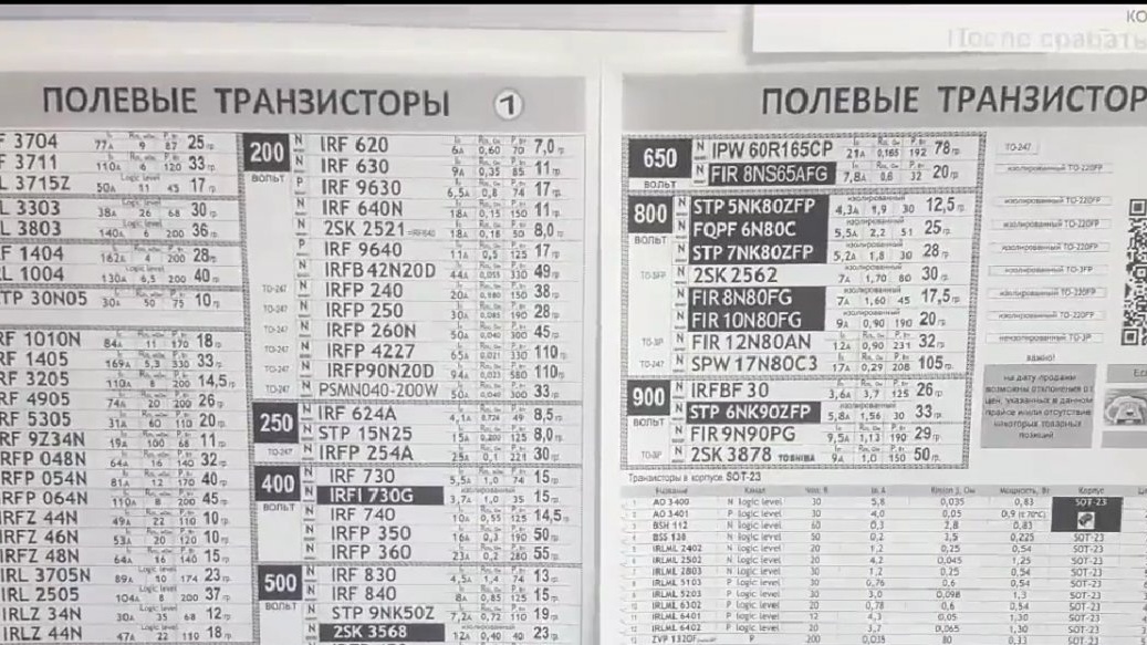
And here the minuses of a synchronous rectifier come up, they appear in the ratio of price, transistor voltage and open channel resistance.

As you can see, the higher the voltage, the greater the resistance, and if the resistance is low, then the price of this transistor is quite high. But then everyone will decide whether he needs such a rectifier or not.
In order to optimally choose a transistor, we need to understand how much power it will dissipate. Grandma Ohm’s law will help us with this.
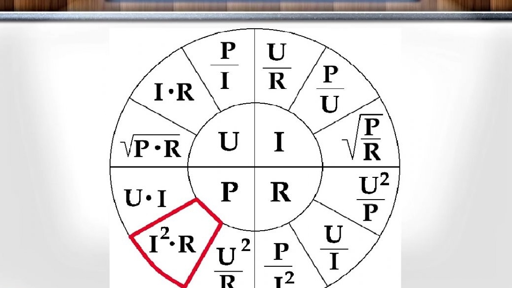
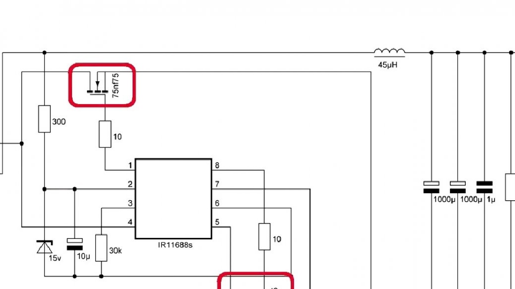
Select the transistor in double amplitude. The price-to-resistance ratio of the channel, the choice fell on 75nf75.
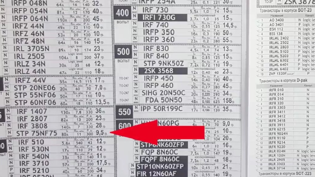
After calculating for a current of 10A, we obtain a power output of 1.1W. Now compare the synchronous rectifier with a schottky diode. With the same 10A we get 4W. The result is obvious.
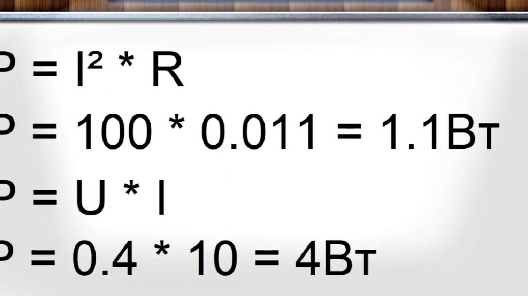
In general, the meaning of such a rectifier is as follows, at low voltages it is several times better than a diode, but with an increase in voltage the picture already becomes not so beautiful.
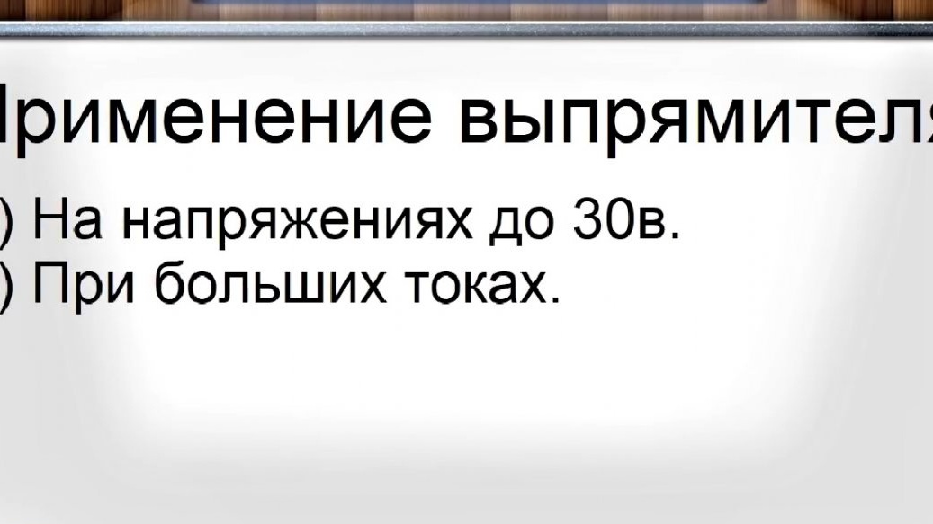
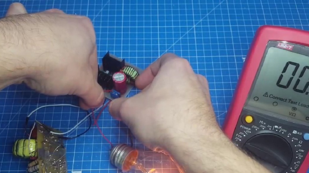
The price of components is high, and the efficiency is a couple of percent higher. Let's see how the device works. We connect the secondary circuit with wires directly to the board and watch the output voltage, it is about 24V, which corresponds to the previously calculated.
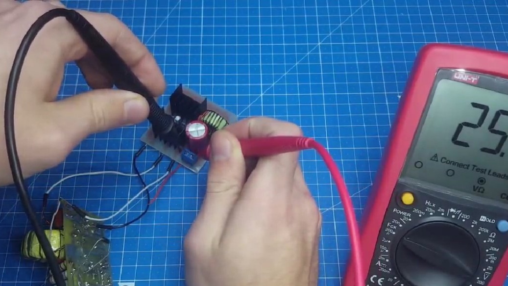
This means that the board is operating normally. It is not advisable to conduct a heating test since the driver is weak. Now we are only checking performance.
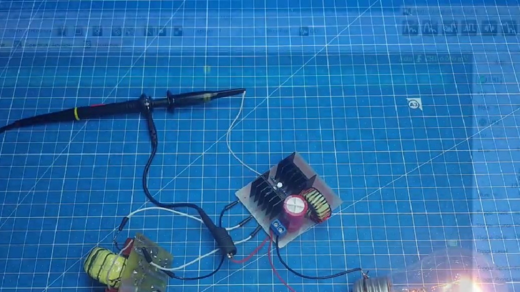
Now, to demonstrate the work, we can stand the oscilloscope probe on the gate of the transistor and see how it opens.
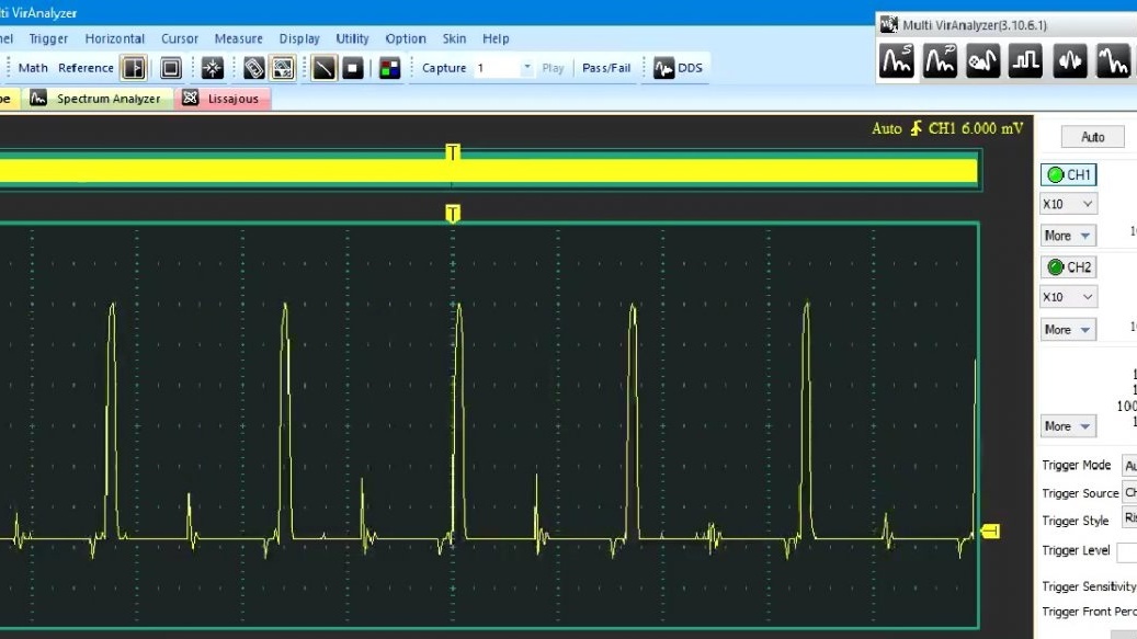
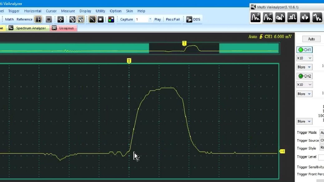
As you can see, the momentum is a bit overwhelmed. This means that switching losses will be added to the heating, but they are not so significant.
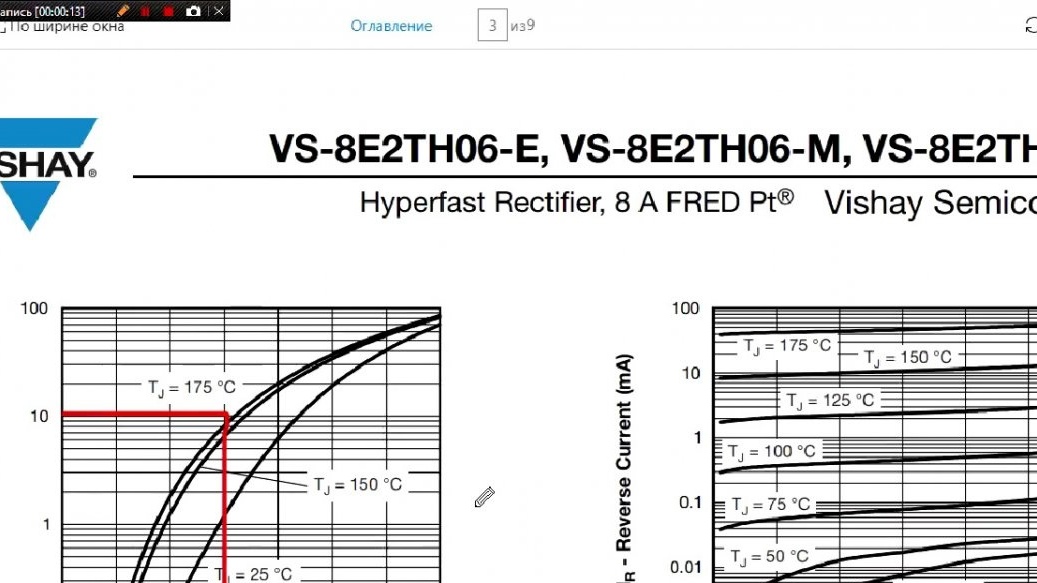
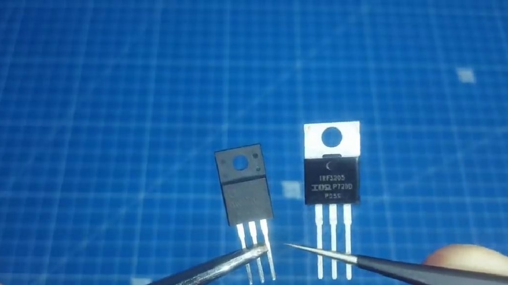
Yes, and yet, during the construction of this rectifier, you can easily step on the rake. They appear in the form of non-original transistors, in which the open channel resistance is much more stated in the datasheet. This is now a very relevant topic.
Well, this is the time to end. Thank you for attention. See you soon!