
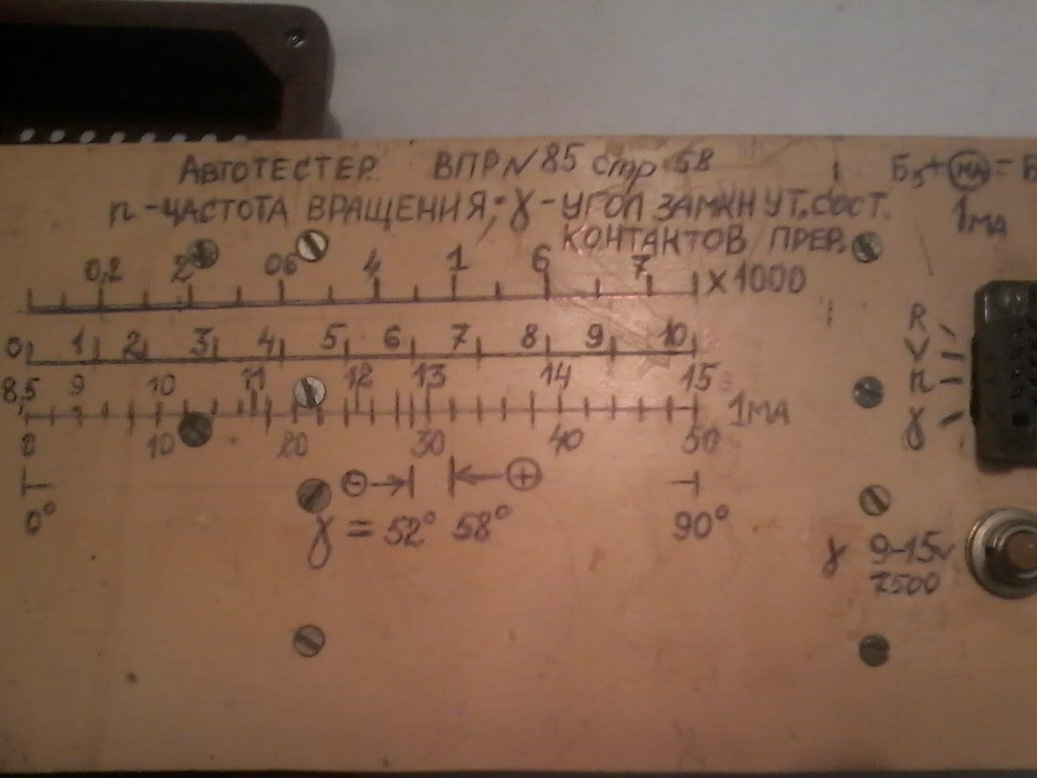
Hello!!! In 2010, I did homemade, which improves the maintenance of your car. With this device, you can measure the resistance of automobile circuits, the engine speed -n, and the closed angle of the breaker contacts - j. This is a car tester.
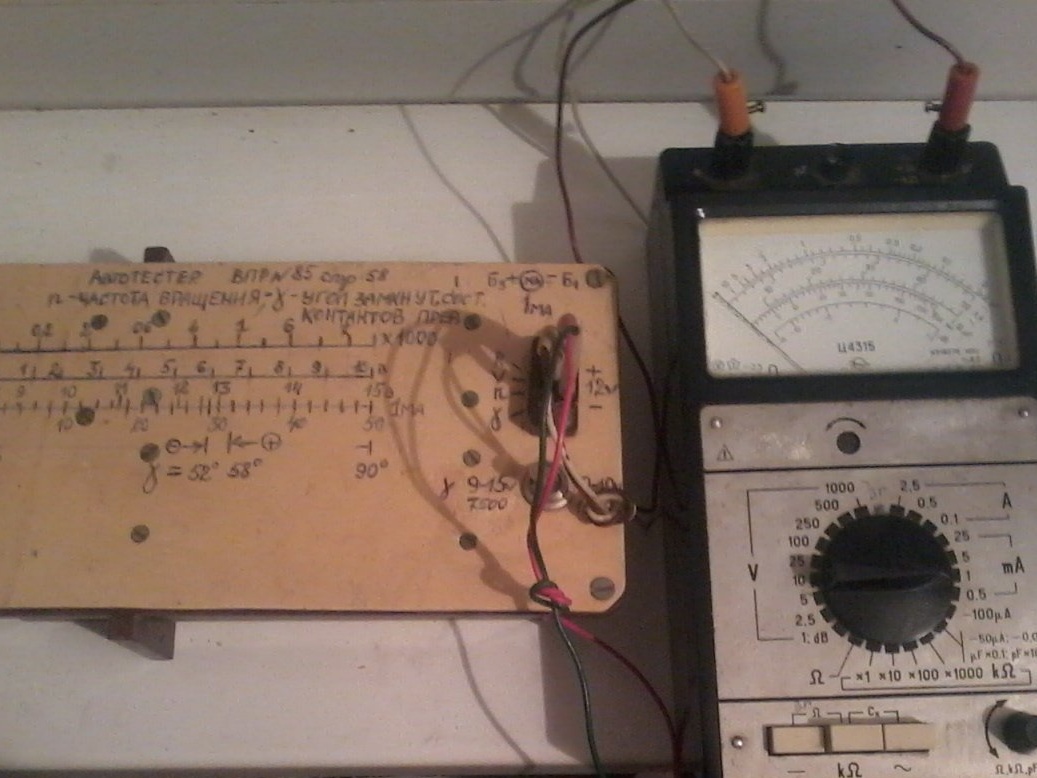
Some of you will say why such a device, if almost all drivers drive injection cars? But in my region, a third of drivers still have the usual "Lada" with a contact ignition system. But for them this device can come in handy. The tester circuit is shown in the photo.
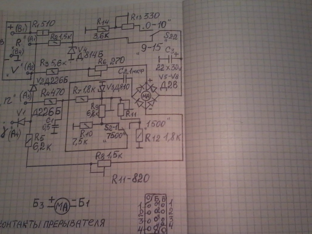
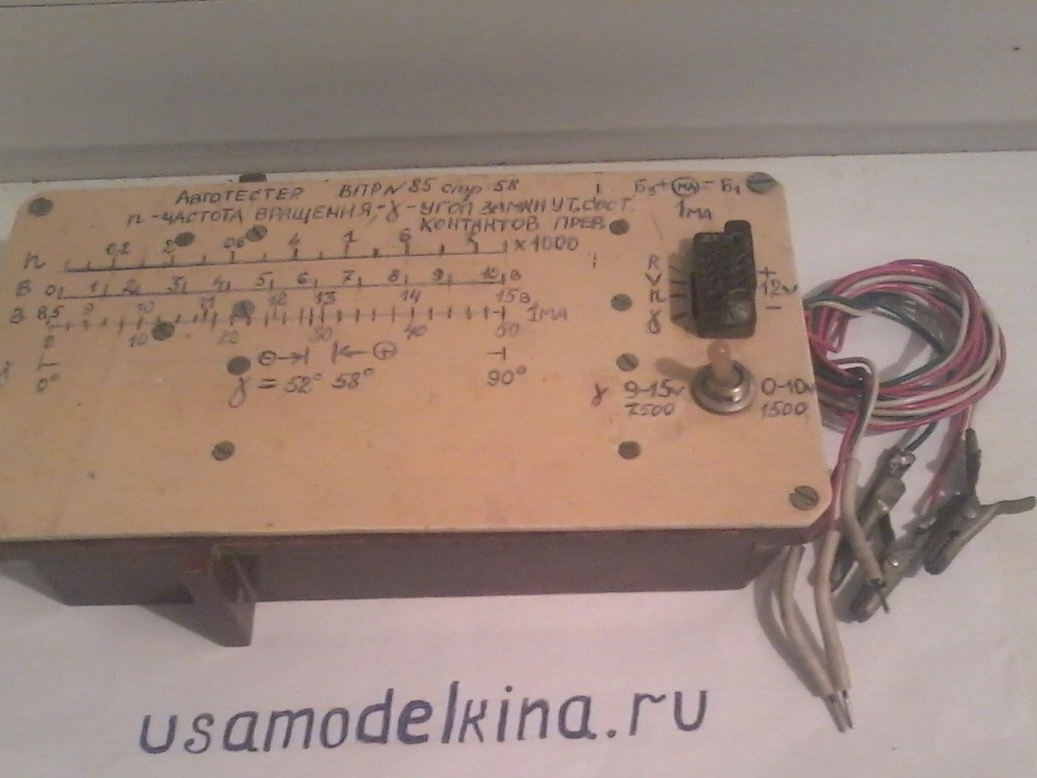
I took the circuit from the magazine "To help the radio amateur" No. 85. At the input of the circuit there is a 13-pin military connector of the Mama type. This simplified the design of the device. Its pin numbering is shown in the diagram. Instead of the 1mA device used by the author, I used the usual Ts-4315 tester, set to the same measurement limit.
How does this device work? It is connected with the “+” and “minus” terminals to the plus and minus of the car battery, and the car breaker contact is connected to the “K” terminal. With electronic ignition in car terminal "K" is connected to the output electronic unit, which is connected to the primary winding of the ignition coil - this is when measuring the parameter of the shaft speed -n. Three wires connecting the device to the car are made of different colors and equipped with crocodile lugs on the one hand, and on the other with plugs that fit tightly into the connector. When measuring the parameter - n, the + terminal is not connected to the vehicle. When measuring the crankshaft rotation speed, the device has two measurement limits - 0-7500 rpm and 0-1500 rpm, which are switched by the S2 toggle switch. The same switch is used to measure voltage in two limits of 9-15V, 0-10V and resistance measurement.
The entire scale of the angle j is uniform, and corresponds to parameters from 0 to 90 degrees. The permissible angle of the closed state of the contacts for the "Lada" is 52-58 degrees. If the readings of the device are located to the left of the label 52, it is necessary to reduce the gap between the contact breaker, and if to the right of the label 58 degrees, it is necessary to increase the gap between the contacts.In order to assemble this device, we need such radio components and tools.
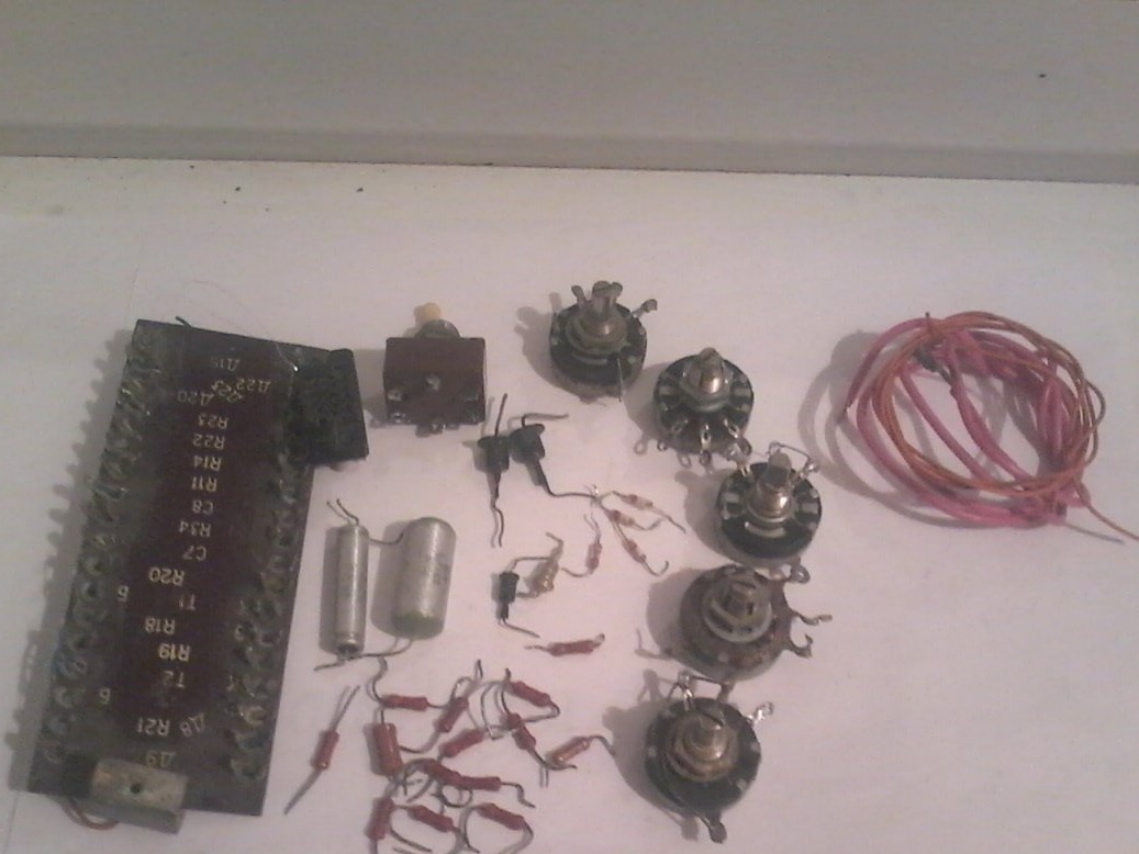
1 - toggle switch TP -1 / 2; circuit boards, mounting wires; Resistors SP -1A -270 ohm; 1.5 com; 6.8 com; 1 room; 2.2 com; fixed resistors MLT -1 W 510 ohms; at 0.25 watts - 1.5 com; 5.6 com; 470 ohm; 6, 2 com; 1.8 Kom - two; 7.5 com; 3.6 com; 0.5 microfarad MBM capacitor; and 1 microfarad; electrolytic capacitor 22mkf at 30 v; D2V diodes –4 pcs; crocodile clips - three pcs; 13 pin connector; Zener diodes D814B; and D810; D226B diodes - two pcs.
2 - soldering accessories.
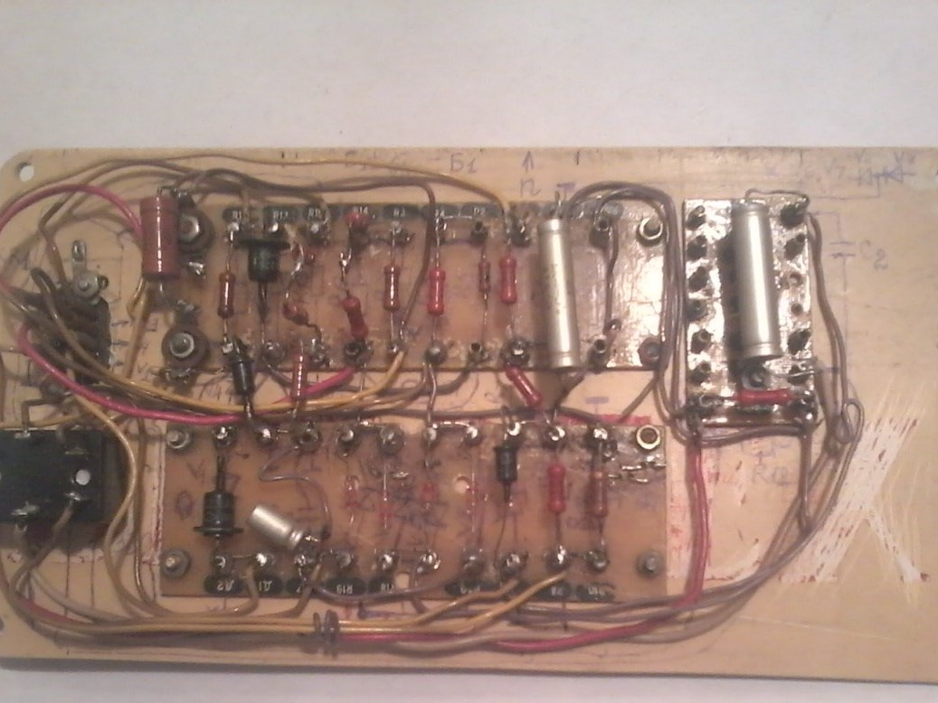
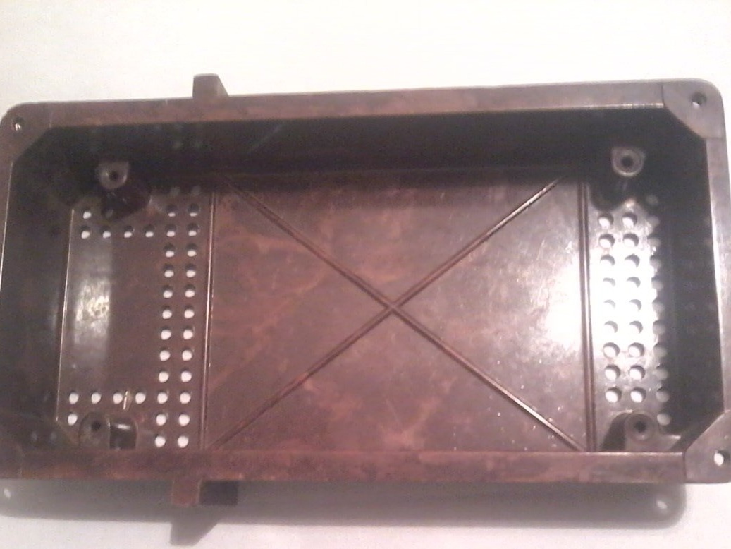
Step 1. Assembling is carried out with known-good radio components. All these checks were shown by me in previous homemade products. For the existing case, make the top cover. Next, I place on it a connector, a toggle switch, circuit boards.
Step 2. On this cover, solder the entire circuit of the device.
Then we set up the device in the following sequence. Why do we apply “B1” plus to the terminals of the connector, and minus 15v from the power supply to “B4”?
We put the S2 switch in the 9-15v position, connect the Ts-4315 device to the terminals of the B3 connector - plus, B1 - minus the device. The measurement limit of the Ts-4315 is set to 1mA. We achieve the installation of the arrow of the device in the extreme right position using resistor R6. After that, reducing the input voltage after 1V, mark the marks on the scale. Then we put the S2 toggle switch in a different position and do the same manipulations as before, only change the input voltage to 10 volts, using the resistor R13. Then, to measure the angle j - the toggle switch S2 we put in position "9-15v", close the terminals "K" and "minus" with each other, using resistor R8 we achieve the maximum deviation of the arrow of the device. To check the resistances, we supply a voltage of 10 V to the input of the tester, connect a resistance shop between the terminals “K” and “minus”, and calibrate the scale of the device. When setting "n", the S2 toggle switch is in the "1500 rpm" position, we supply an alternating voltage of 12V to the "K" and "minus" terminals. Resistor R11 set the arrow of the device to the last division of the scale. By switching the toggle switch S2 to another position with the resistor R9, we set the arrow of the device by dividing 0.2 of the entire scale. After that, we replace all variable resistors with constant, measuring their values before that. Establishment is completed. Then I collect everything in the case, put the scale on the top cover of the device.
That's all the device is assembled and configured.