All modern cars they have the “Daytime Running Lights” (DRL) mode, on old foreign cars and domestic cars there is no such “wealth”, each is blown out in its own way. In this article I describe my "torment" of invention. I have an old Opel Vectra B 1996
The idea to develop an economical and automatic inclusion of daylight using foglights was born to me a long time ago (I would not lie in 2011-12). First I tried on all sorts of Chinese LED bulbs, headlights. All this required changes either in the headlight, or hanging / gluing to the bumper, etc. This did not suit me, besides, I saw on other cars how LED lamps begin to blink or do not shine evenly. The option with the inclusion of foglights led to the fact that the battery would sit faster during close trips around the city, especially in winter. I also dismissed the included dimensions instead of the DRL, due to stealth in the daytime and due to the fact that they can accidentally be left turned on in the parking lot. And if you forget to turn them on, then you could run into a fine.
And so, the task: automatically turn on foglights sparingly, turn it off when the dimensions, dipped beam are turned on or when the ignition is turned off.
The first circuit was born on relay logic.
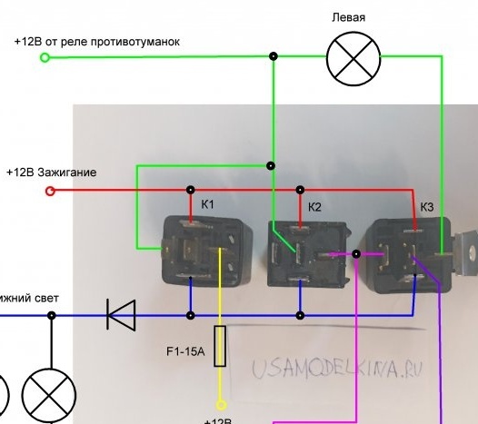
Connection option in the photo:
When the ignition is turned on and the dipped beam is off, the DRL mode is automatically turned on. Fog lights are connected in series to + 12V, respectively, consume less.
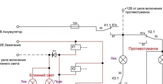
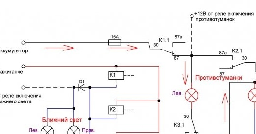
Description of the circuit: when the ignition is turned on (low beam off), the current flows through the parallel connected relay coils K1, K2, K3, then through the direct transition of the open diode D1, and through the low beam to ground. The resistance of the filament of the low-beam lamps is small, compared with the resistance of the relay windings, so almost the entire supply voltage will be present on the windings. The relays turn on, contact K1.1 supplies 12V, and contacts K2.1 and K3.1 change the connection of the fog lamps from parallel to in series.
When you turn on the low beam on the minus terminals of the relay windings, the mass disappears, the relays are disconnected and the DRL is turned off. Diode D1 in the circuit is needed to prevent the relay from turning on when the ignition is off and the dipped beam is on. On the Opel Vectra B, the dipped beam is turned on regardless of the ignition.
Description Explanation:
With the pluses: after all, automation, additional heating of the fog lamps with half voltage, the price of 3 relays and additional wires, a fat minus: cut the standard wires, stretch the wires to each fog and the low brightness of the fog lamps in daylight mode.
I decided to make the next development for the implementation of the task from what I have at hand electronically without major changes in wiring.
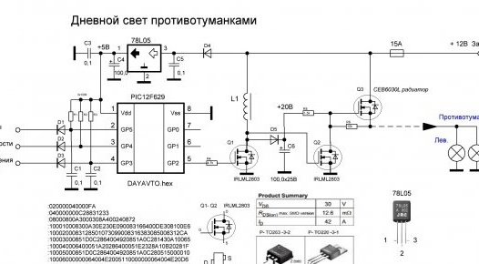
Task: Automation + PWM fog control, connection to standard wiring in the car. Implemented the circuit on an inexpensive microcontroller PIC12F629. The program was written in assembler.
Algorithm: when the vehicle is started, when the vehicle starts to move and the dimensions are off, a low voltage is applied to the foglights using a PWM (approximately 9V). Deactivation of the DRL mode occurs when the ignition is turned off, the dimensions / dipped beam / fog lights are turned on. Motion control is constant, if the dimensions in the movement were turned on, and then turned off - DRL mode is turned on.
I did not start disabling DRL on a stopped car in a traffic jam or at a traffic light, because it will prove to my DPS nickname that you automatically turn on the light in traffic, it will become more expensive. In addition, you can turn off the mode by manually turning the dimensions on and off.
The scheme is working, it has been standing on my Opel for about 7 years and, compared with the constantly turned on foglights like DRL, it is noticed that in this mode the battery is discharged less. I did not measure anything, purely analysis. While writing the article, I suddenly realized that during all this time I have NEVER CHANGED THE BULBS in the fog! Although it used to be, there are ordinary domestic ones.
Details that will be needed to repeat:
1. PIC12F629 -1; (Chip-Dip price - 97 rubles, bought at 37 rubles.)
2. -1; (5V voltage regulator)
3. All resistors 0.125W, ratings on the circuit;
4. Diodes D1, D2, D3 - 1N1401. (any low power)
5. Diodes D4, D5 - 1N1404; (more powerful, 1A)
6. Ceramic and electrolytic capacitors are indicated in the diagram.
7. Choke L1 - used a coil from a car relay.
8. IRLML2803 - 2pcs.; MOSFET field-effect transistor (any N-type suitable for a current of 1-5A and a voltage of at least 20V, for example SMD AO3400, bought for 96 rubles - 100 pcs.)
9. -1; MOSFET, a powerful N-type field effect transistor. It did not turn out to be a powerful P-type field effect transistor, but a large number of powerful N-type transistors are present on old motherboards, one of which I use here.
Full opening of the transistor is achieved if the control voltage at the gate is greater than 16V. At 12V, the gate at the gate along with the frequency changed the amplitude at the output of the transistor and, as a result, its strong heating, solved this problem by adding L1, D5, C6, and now the gate PWM with an amplitude of 20V. Frequency 10kHz. A powerful transistor must be installed on the radiator, I have on the ribbed radiator from the computer power supply 6x6cm. I assembled the circuit on a breadboard, and placed the finished device in a block from the alarm.
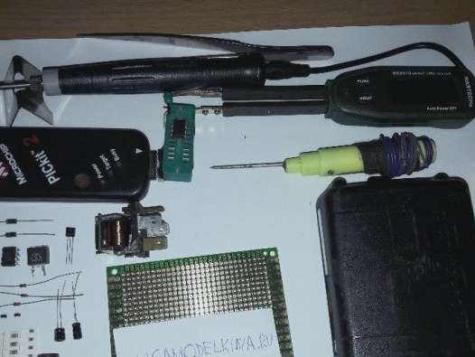
For firmware controller requires a programmer, I programmed using PICKit2.
: 020000040000FA
: 040000000C28831233
: 08000800A3000308A400240872
: 100010008300A30E230E090083166400DE308100E6
: 1000200083128501073099008316383085008312CA
: 10003000851D0C2864004920851A0C281430A10065
: 100040006400051A20286400051E2328A10B20281F
: 10005000851D0C2864004920851A0C280515000010
: 10006000000064004E2005110000000064004E20D6
: 10007000851D0C286400851A0C282E280530A20046
: 100080001430A10064000000A10B4228A20B4028FC
: 100090000800A7016400A70B4A2808001930A70030
: 0600A000A70B5028080028
: 02400E00CC0FD5
: 00000001FF
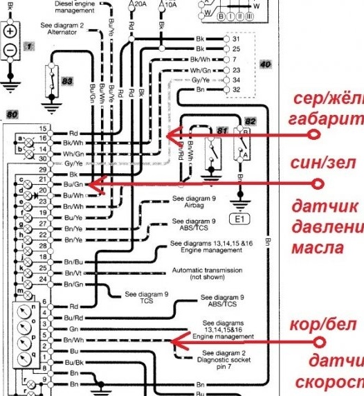
The finished device is not difficult to connect. Signals - dimensions, speed sensor, emergency oil pressure sensor (signal from the generator is not suitable) is on the instrument panel connector on almost all foreign cars until 2005. In domestic there are also new ones. Power + 12V connect through a 15A fuse to the ignition (indicated in the diagrams as terminal 15), or better to ACC (indicated in the diagrams to terminal 75), the output of the device is to fog. If you have questions, I can answer in the comments. I can help in programming the controller or send the programmed one.
Connection diagram in the dashboard Opel Vectra B:


