It is proposed to consider a method of short-term inclusion of an LED strip. After a certain time, after turning on, the lighting is automatically turned off. This allows you to save electricity, which is wasted when the lighting is on or not turned off due to forgetfulness. This inclusion option is advisable if you need a short illumination of the corridor, cabinet, pantry.
In this case, there was a need to turn on the lighting of the interfloor spiral staircase, for the period of passage through it at night. Approaching the stairs, press the button on the railing. The lighting of the stairs installed under the railing of the LED strip for the previously specified period is turned on. After the set time, the staircase lighting is automatically turned off. To move backward, a similar button is installed at the other end of the stair railing. To indicate the buttons in the dark, they are backlit by constantly on single LEDs.
If you need a longer inclusion of lighting, parallel to the buttons you need to connect a switch with fixed positions. In this case, the lighting will be on when the switch is on, and after it is turned off, it will stop after the appointed time.
The current consumption of the circuit breaker in standby mode is 4-5 mA.
An option to automatically turn on the lights when entering the stairs will be the location of the timer buttons below the extreme, slightly spring-loaded steps of the stairs.
Turning on the power of the device, at night, is performed by the toggle switch. To automatically turn off the power during daylight hours, the device can be supplemented with a simple photo relay installed in the same case.
Device Options
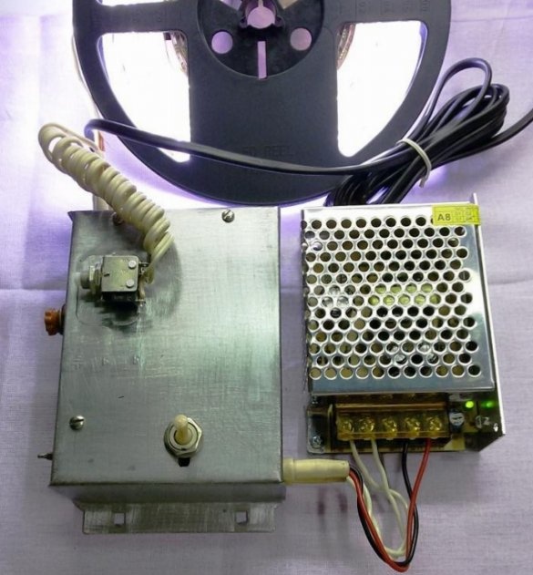
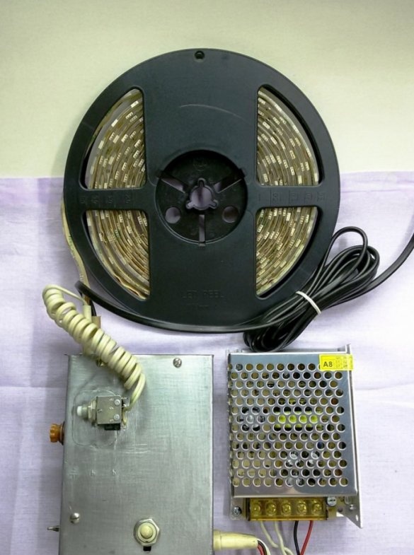
To manufacture a device (timer) that allows you to turn on the LED strip for a certain time, you must purchase:
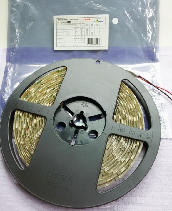
1. LED strip LSW 5050 12V 60led / m CW (daylight, cold white light) 5m 72W IP65.
Dust and moisture protection: 65 IP
LEDs: 5050 mm
Number of LEDs per 1 m: 60 pcs.
Power at 1 m: 14 W
Band Length: 5m
Execution: tight
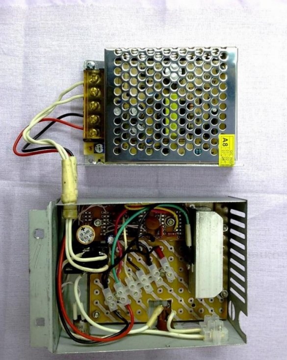
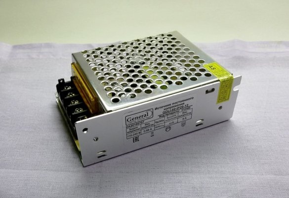
2. LED driver General GDLI-60-IP20-12.
Power 60W, degree of protection IP20, output voltage 12 V.
Designed to convert the input AC voltage of 220 V into a constant stabilized voltage of 12 V, to power LED light sources (tapes, modules), as well as their protection during the service life. The driver has built-in protection against power surges, overheating, overload and short circuit. The total power of the connected tapes is not more than 60 watts. For reliable operation of the power supply, it is necessary to have a power reserve for the load of up to 20%.
Technical Specifications GDLI-60-IP20-12:
Load range: 0-60w
Input voltage: AC 176-264 V
Output voltage: DC 12V
Max. output current: 5A
Indication Type LED
Service Life: 30,000 hours
Dimensions (L * W * H): 85x58x38 mm
Manufacturer "General"
Country of manufacture China
3. A set of radio components according to the following timer circuit.
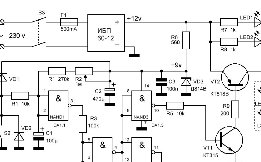
Timer circuit
A device for turning on lighting for a period of 15 seconds to 2 minutes and subsequent automatic shutdown (timer) can be performed according to the scheme:
Timer Description
The device’s power source is a GDLI-60-IP20-12 switching power supply (UPS) connected to a 230-volt alternating current network via an S3 toggle switch. To the UPS output (+ 12V), through the limiting resistors R7 and R8, two indicator LEDs LED1 and LED2 are constantly connected, illuminating buttons S1 and S2 including an LED strip.
Also, a delay unit made on the DA1 K176LA7 chip is constantly connected to the output of the UPS. An equivalent substitute is the K561LA7, K561LE5, K176LE5 microcircuit. The output signal of the delay unit is amplified by the transistor T1 and entering the power transistor T2 turns the LED strip on or off.
The circuit that sets the shutdown delay interval consists of capacitor C1 and resistors R1 (minimum delay time) and variable R2. Resistor R6 reduces the supply voltage of the chip to a nominal voltage of 9 volts. Capacitors C2 and C3 smooth and filter the supply voltage of the chip.
When the timer is in standby mode, capacitor C1 is charged through resistors R1 and R2. The voltage at inputs 1 and 2 of DA1.1 is at the level of logical unit (1).
Due to the inversion of the chip elements, the output 3 of DA1.1 and the inputs of DA1.2 will have a logical zero (0), the output of DA1.2 and the inputs DA1.3 and DA1.4 will be logic one (1). Therefore, at the output 10 of DA1.3, a logic zero (0) is set, the transistors ѴТ1 and ѴТ2 will be closed and the voltage to the LED strip is not supplied.
When you press the button S1 or S2, short-circuited capacitor C1 quickly discharges. At the same time, the voltage at C1 and inputs DA1.1 drops to zero (0), the logic level at output 10 DA1.3 changes to (1), transistors ѴТ1 and ѴТ2 open and the LED strip turns on.
When the button contacts open, the capacitor C1 begins to slowly charge through resistors R1 and R2 with a large resistance. After some time, the voltage on C1 rises to the level of a logical unit (1). At the same time, output 10 DA1.3 sets a logical zero, the lighting turns off, and the timer goes into standby mode. Off delay adjustment is performed by variable resistor R2.
In the process of slowly increasing the voltage on C1, the DA1.1 element, between logical zero and one, may be in an unstable mode. To prevent instability of the circuit, a Schmitt trigger on the elements DA1.2 and DA1.4 has been added to it. Due to the hysteresis during the operation of the Schmitt trigger, only stable values can be set at its output, zero or one.
Making a timer
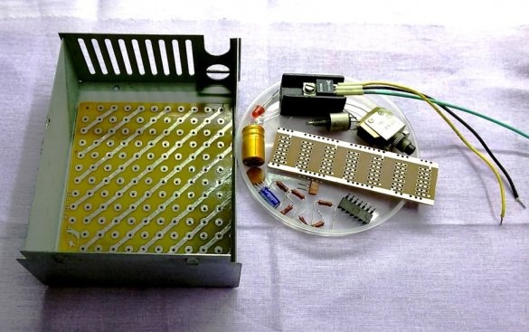
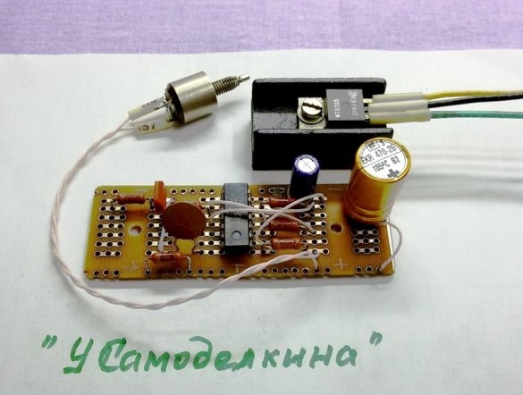
1. We complete the device with radio components according to the timer circuit.
We select or manufacture a timer case from a metal sheet with a thickness of 0.5 ... 0.7 mm. According to the internal dimensions of the case, we cut out a textolite panel to place timer components on it and isolate them from the metal of the case. From a typical circuit board, we cut out the working board for desoldering e schemes.
The low-power control transistor ѴТ1 (КТ315) can be replaced with the BC547.
The power transistor ѴТ2 (КТ818В) can be replaced by domestic or imported, similar in power and voltage. Due to the large flowing current, the transistor T2 must be installed on the radiator.
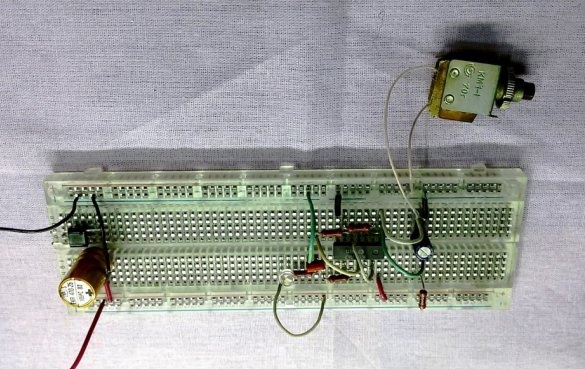
2. Installation and debugging of the delay assembly
We assemble and debug the delay assembly on the universal circuit board on the DA1 K176LA7 chip. We connect the circuit to the laboratory power supply, set the supply voltage to 9 V. To the output of the microcircuit (pin 10), through the resistor R5 (10k) we connect the transistor ѴТ1 (see diagram). Its collector, through a 1k resistor and an LED, is connected to the positive power bus. We press the button and check the operation of the delay node by turning the LED on and off.
The establishment of special difficulties does not cause. Need resistor R2 to set the desired delay off. If the exposure time is short, it may be necessary to increase the capacitance of capacitor C1 or choose the ratings R1 and R2.
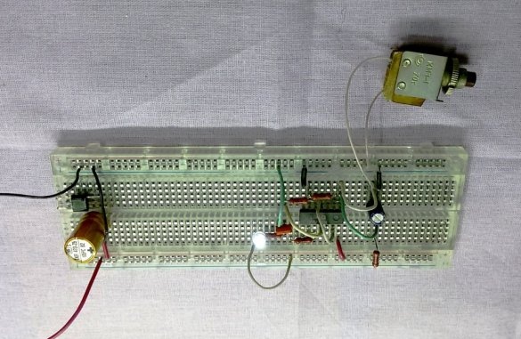
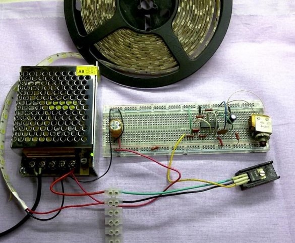
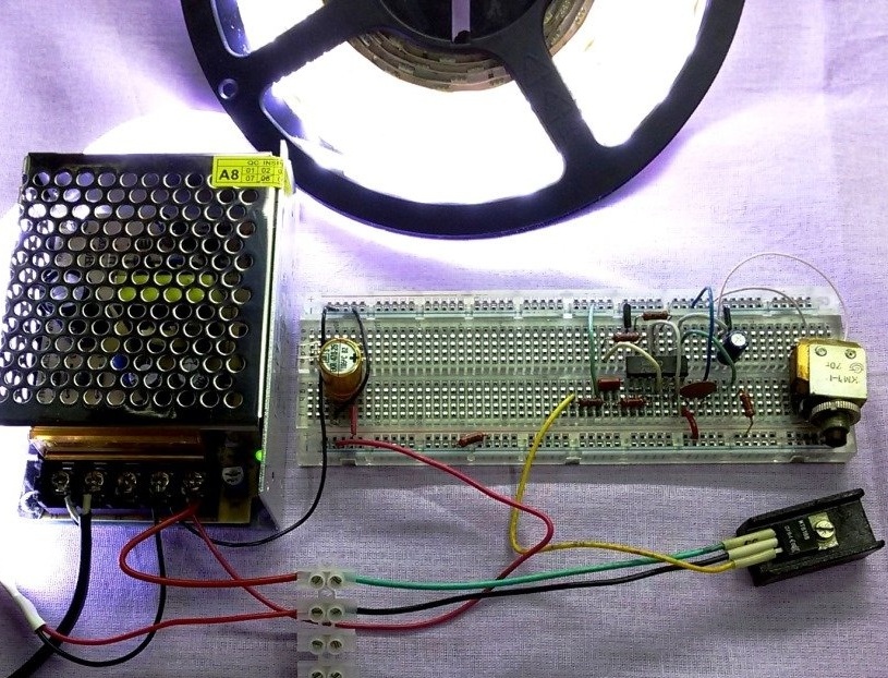
3. Test the delay unit under load.
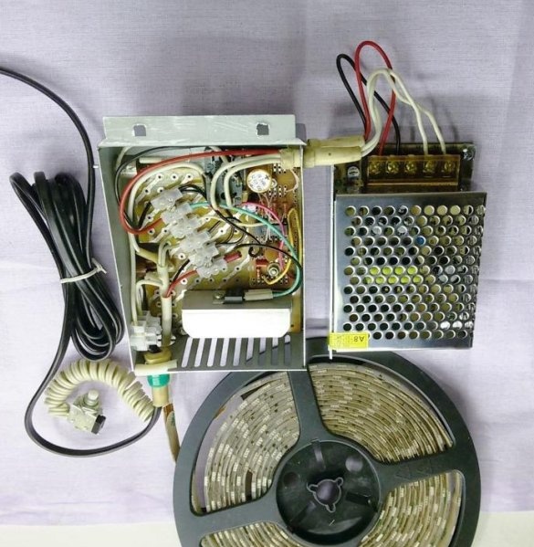
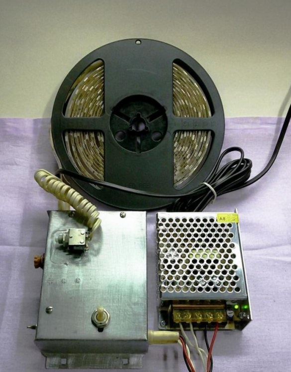
We cut off the length of the LED strip necessary for installation, without forgetting about the power reserve of up to 20%. Having removed the LED from the wiring diagram, we supplement the timer circuit to the above. We connect the power transistor ѴТ2 on the radiator, the switching power supply and the working segment of the LED strip (in the above design, the working length of the LED strip is 4 m).
Check the timer under full load.
4. Fabrication of the delay assembly
We transfer and solder the circuit of the delay node on the work board.
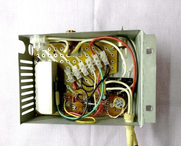
5. Installation and assembly of the timer.
All components and components of the timer are located and fixed on the textolite panel. This is a delay node board mounted on a radiator, a power transistor, a block for connecting external nodes. At this stage, the transistor heatsink has been replaced. The new radiator is made of aluminum, has a large thermal conductivity and recoil area.
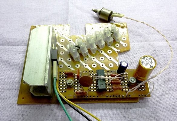
We place the assembled panel in the case, mark and process the holes for installing the fuse case, variable resistance to adjust the shutter speed, the power switch and the conclusions of the power wires for 12 and 230 Volts.
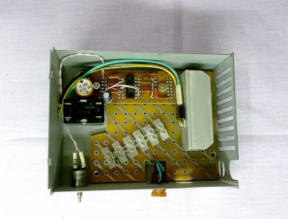
We mark, drill holes and fix the panel in the case with the help of M3 screws with remote plastic gaskets for electrical insulation.
We carry out the electrical installation of all timer nodes, connect the UPS and the LED strip.
We collect, turn on, the timer works according to the declared parameters.