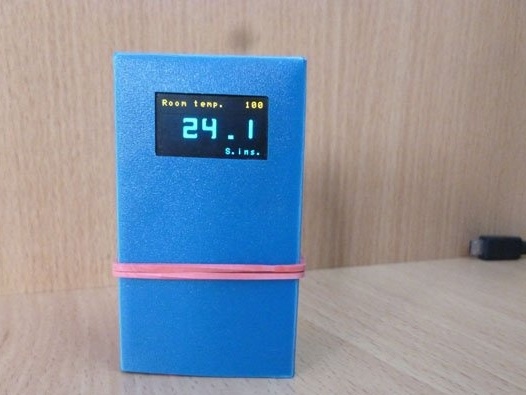
Hello everyone and have a nice day or evening. This time I will share the instructions for making a room clock with a thermometer. The watch's computing center will be Attiny85, assembled on a board from Digispark. To display the clock - Oled display. Thermometer - the well-known ds18b20. For power we take li-ion 18650 (they can be obtained from an old battery from a laptop). And add a display of the battery level. As in all my previous watches, we will do without the RTC (real time clock) module.
We collect all that is necessary:
- Digispark Attiny85 (micro USB version)
- ds18b20 (in a plastic case)
- Oled screen with a resolution of 128x64, I2C
- 2pcs 18650 batteries or an old Li-ion laptop battery
- Resistors (3.3 kΩ, 4.7 kΩ, 10 kΩ)
- Thin plastic (for housing)
- Connecting wires of different colors
- ISP programmer (or any Arduino pay)
- Button
- Dupont connectors 2.54 mm "mother", "father"
- Stationery knife, double-sided tape, electrical tape, hotmelt
- Everything for soldering (soldering iron, rosin, solder)
Step 1 Case.
The future watch case will be made of thin plastic. You can buy a sheet of such plastic in a specialized store or order on aliexpress. And you can (not to wait and not look) to go to the clerical office and buy a plastic paper folder of your favorite color. Dimensions of the future watch: width - 40 mm, thickness - 30 mm, height - 70 mm. According to the diagram below, we cut out a scan from plastic:
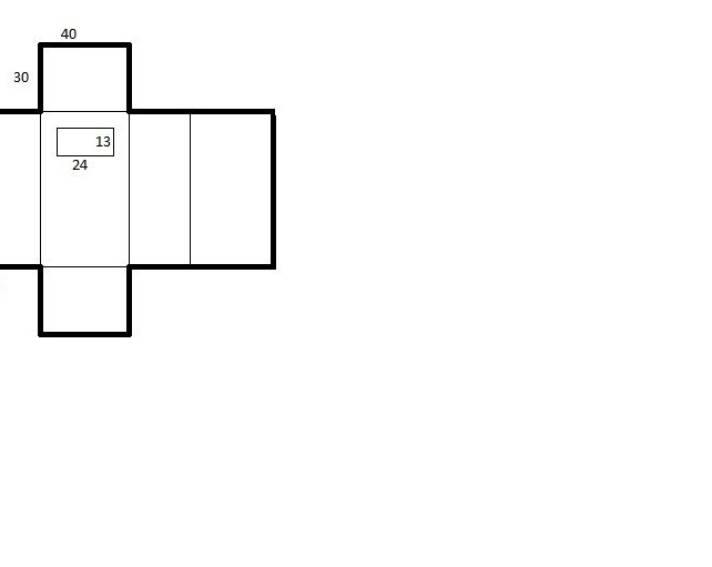
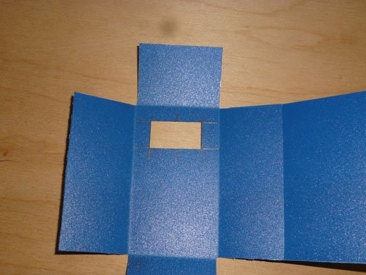
We cut along thick lines, bend gently along thin lines. We cut out the rectangle in the middle using a clerical knife, this is a window for display. As a result, we get a scan of plastic:
We pass to Attiny.
Step 2 Attiny + Oled.
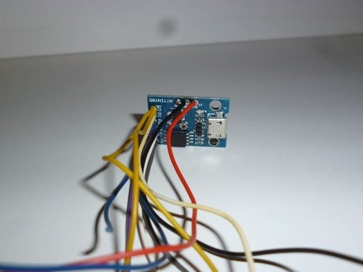
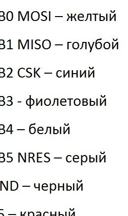
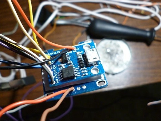
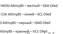
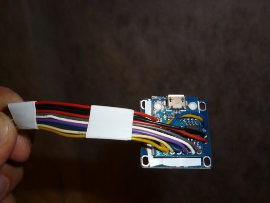
As I said, in our heart homemade will be Attiny 85. It is best to purchase this chip, immediately soldered to the board along with a voltage regulator and harness. Digispark Attiny85 is well suited. Choose the version with micro-USB on the board. Other modifications to the board will not fit in size. It happens that this board is sold with Dupon “male” connectors already soldered. If so, solder all the connectors. We collect colored wires. We need 10 centimeters in different colors. We solder them in Attiny and write down which wire, which conclusion corresponds to. The wires P0 and P2 must be soldered in two wires. The second pair is needed to connect the Oled screen. We get the following:
I wrote the following diagram on the wire:
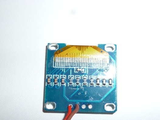
The screen is small (to match the controller), but it looks beautiful. OLED (organic light-emitting diode) is a graphic display. There is no backlight, and instead, each pixel is an independent LED. Screen sizes - 0.96 inches.Resolution 128x64. Connected via I2C bus. Uses just two wires to connect with Attiny. They come in different colors, choose to your taste. I liked the blue with a yellow stripe at the top. We act similarly to Digispark. If there are soldered connectors - solder them. Solder, for now, only the power wires:
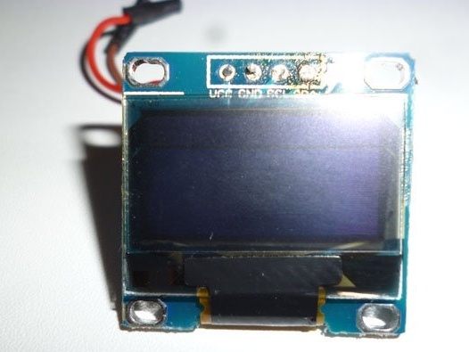
Be careful when soldering, do not damage the cable with a soldering iron on the display:
We connect the boards using double-sided tape:
We solder the Digispark Attiny and Oled display together according to the scheme (the colors of the wires may vary, the main thing is not to mess with the conclusions):
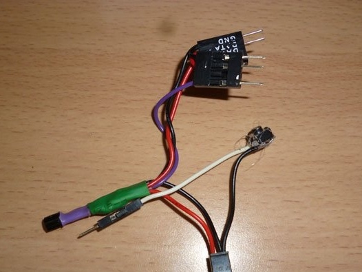
For convenience and order we collect all the wires together. You can twist them with electrical tape so as not to get confused:
At the end of all wires, we attach the Dupont “mother” connector, insert it into the insulators and wind it all together with electrical tape to make the connector. We also record the pinout of the connector:
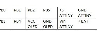
The pinout should be like this, since in the future we will connect a wire for firmware or other watch elements to the connector.
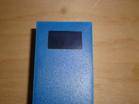
We glue the resulting structure into the case, and do not forget to glue the case itself, leaving one moan not glued, for further manipulations:
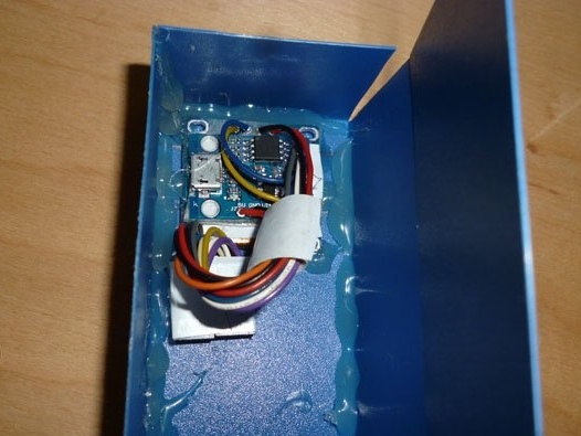
When gluing, pay attention that the screen is even:
Step 3 Power.
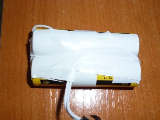
For power we will use two Li-ion elements. Type 18650. You can purchase them separately. In this case, solder them in parallel, isolate and output the connector for connection and subsequent charging:
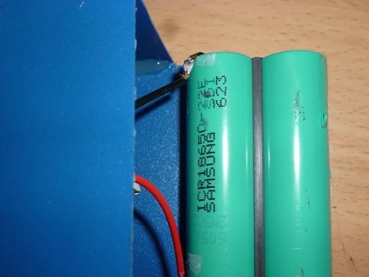
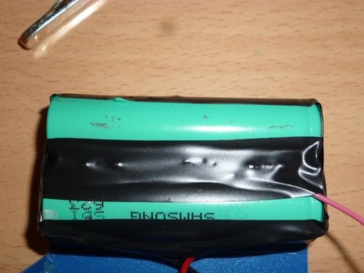
Many have older laptops. Whether they no longer work or work through time. Even if the laptop’s battery is already bad and not suitable for its intended use, it can be used for all kinds of homemade products. In our case, for a watch. We take the battery from the laptop:
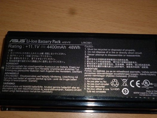
The main thing is that he be Li-ion. We carefully disassemble it, you need to open the plastic case, so as not to damage the element inside. Most often, the battery is divided into two elements connected in parallel. We take them out and separate one pair from the rest:
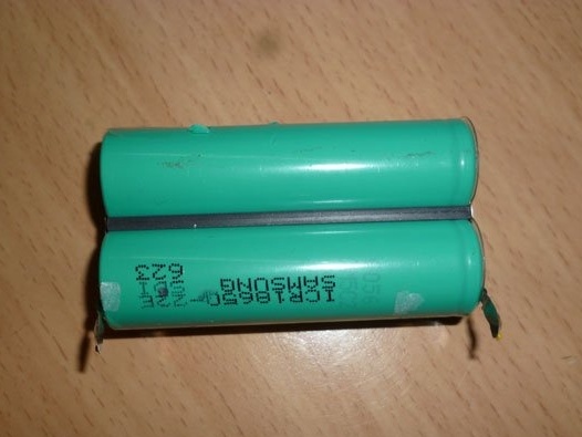
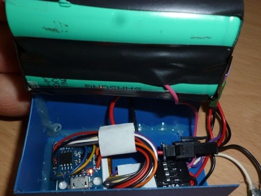
It is best to solder to the contact pads:
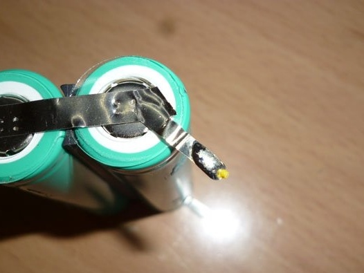
Glue this pair to the back of the watch:
Step 4 Determining the battery charge.
A convenient function of the watch is to indicate the battery charge. We will determine the degree of charge by voltage. The minimum voltage for these batteries is 2.4 V. It cannot be discharged further. The maximum voltage is 4.2 V.
The voltage measurement at the analog port is always relative to some other voltage. We cannot use the AREF pin of the microcontroller, which serves to set the reference voltage. It is also impossible to measure the voltage with respect to the supply voltage (the ratio will always be the same). Therefore, we will determine the voltage in relation to the internal reference voltage or Vbg (Bandgap reference voltage). It is 1.1 V. Now we need to calculate the voltage divider for our battery, so that at maximum charge (4.2 V) the divider had (1.1 V). You can calculate by the formula:
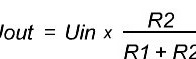
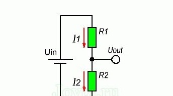
Or use
R1 take a face value of 10 kOhm. Then R2 we get 3.55 KOhm, the closest suitable one from the standard values of 3.3 KOhm, and take it. Measurements are made between the internal voltage and GND, so the 3.3 KΩ resistor is soldered to the minus, and 10 KΩ to the plus. We place the resistors on the battery, we withdraw the wire from the divider.
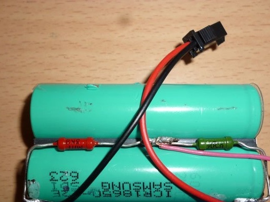
We isolate all contacts in order to avoid short circuit:
The wire from the divider will be connected to PB4.
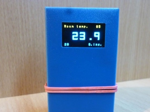
Step 5 Measure the temperature.
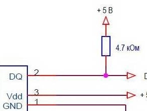
An excellent complement to the watch is the measurement of room temperature. We will use the integrated temperature sensor DS18B20. To work with it, only one wire is required (very useful when using Attiny 85). All measurements are made by himself, the central controller does not bother (Attiny 85 also has excellent memory and so little), we only need to give commands and get results. There are several different connection schemes for this sensor, we will use the option that is optimal for this case, in my opinion.Using external power and a 4.7 kΩ resistor:
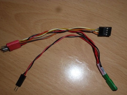
Solder small wires, and fasten the connectors
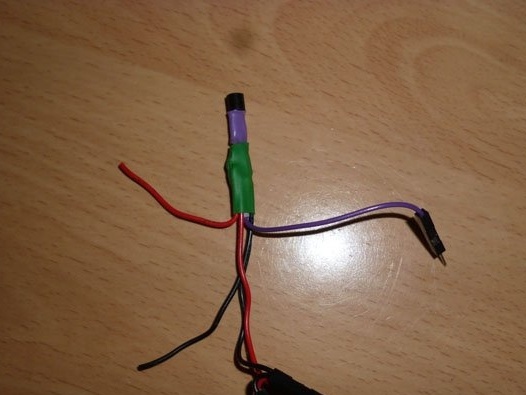
The wire from the DQ sensor is connected to PB 3.
Step 6 Button.
We have few conclusions, but there are many requirements for watches. We will use one button to set the time. We can’t count on more. Solder the wires to the button, one contact from it to GND. Combine with our temperature sensor:
The second contact from the button is connected to PB 1.
Step 7 Preparing the Development Environment
For further work with the sketch, as well as its editing and filling, we need the Arduino IDE. Download this program from:
Now add support for Attiny 85 on Wednesday. Open the Arduion IDE and go along the path:
File - Settings - "Additional Boards Manager URLs" insert the link:
https://raw.githubusercontent.com/damellis/attiny/ide-1.6.x-boards-manager/package_damellis_attiny_index.jsonClick OK.
Go to:
Tools - Board - Boards Manager enter Attiny and click on "attiny by David A. Mellis". Click "Install" and leave put the coffee.
And now about the libraries. They need two:
To work with the Oled display
Temperature sensor control
After downloading these archives, unpack them into the “libraries” folder, which is easy to find by going along the installation path of the Arduino IDE.
Step 8 Programmer.
Digispark Attiny 85 is a great board. Designed to connect to a USB computer. And it can be programmed through it. But Attiny uses a software USB, which in turn takes up 2 KB of 8 KB of memory. This does not suit us, and therefore we will flash Attiny 85 through the ISP interface. And here we need an ISP programmer. If it is not there - it does not matter. Take the Arduino. In my case, Arduino UNO:
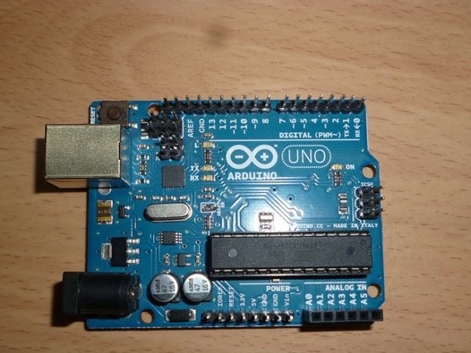
You can take any other compatible board from the Arduino line. We connect to the computer, open the Arduino IDE, select the com port to which the Arduino board is connected, open the sketch in the examples, Arduino ISP and fill it into the board. We also need a wire to quickly connect to Attiny.
The connection is as follows:
D11 - P0
D12 - P1
D13 - P2
D10 - P5
Do not forget about Attiny nutrition.
Step 9 Edit and fill the sketch.
Download sketch
Before filling, you need to edit the sketch.
The ds18b20 integrated sensor, as mentioned earlier, works using the One Wire protocol. Each sensor has its own unique 64-bit address. You need to find the address of your sensor and write it in a sketch. Open the Arduino IDE, follow the path:
File - Examples - Dallas Temperature - OneWireSearch.
Fill the sketch into Arduino. Open the port monitor. You should see the addresses of all connected sensors and their temperature readings. We write down your address. Open my sketch and change the address to your own in the line:
byte addr [8] = {0x28, 0xFF, 0x75, 0x4E, 0x87, 0x16, 0x5, 0x63};To adjust the progress of the clock, use the following constant:
if (micros () - prevmicros & gt; [b] 497000 [/ b]) The larger this value, the slower the clock.
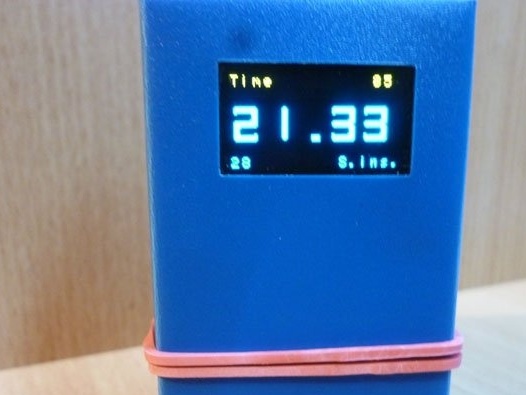
For control, seconds are displayed on the screen:
OzOled.printNumber ((long) sek, 0, 7); // output seconds for accurate tuning Comment out this line to remove seconds.
Now we connect the programmer or Arduino as the programmer, select the com-port, select our board in the Tools menu and set the following parameters:
Board: Attiny 25/45/85
CPU: Attiny 85
Clock: internal 16
Then select in the same menu:
Tools - Programmer - "Arduino as ISP".
And finally:
Sketch - Download via the programmer
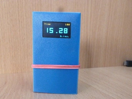
Step 10 Final assembly and launch.
Turn off the programmer and connect the sensor, power and button:
Until the exact course of the clock is configured, you can close the case using bank rubber. When done, you can glue it.