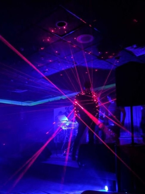
If you see a person from whom the laser beams are beating, don’t be afraid, maybe he made himself the same jacket as the Master from New York. In turn, the master saw the idea of a laser jacket in a clip of a Japanese rock musician and decided to make himself the same.
Let's see what he did.
By the way, one Japanese company produces such a line of "laser" clothing, and even won several international prizes.
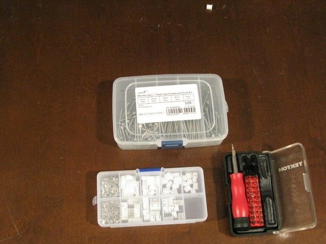
To make such a jacket you will need the following
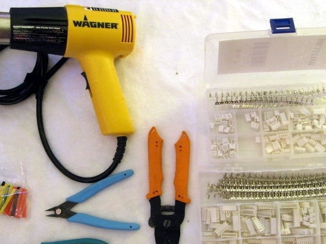
Tools and materials:
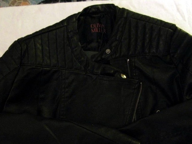
-Jacket;
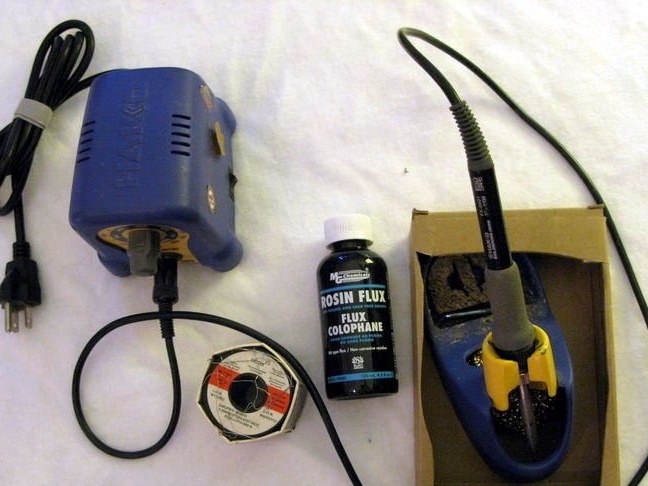
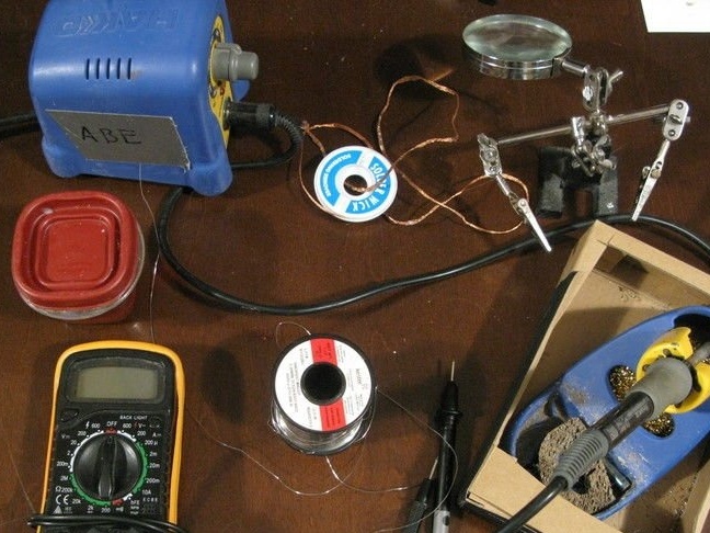
-Soldering iron;
-Multimeter;
-Solder;
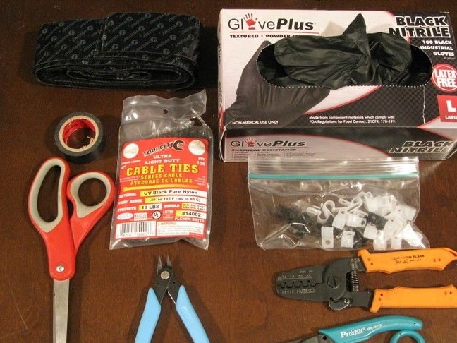
-Nippers;
-Tool for stripping wires;
-Flux;
-Clip "Third hand";
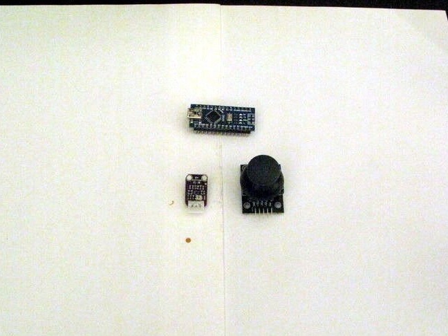
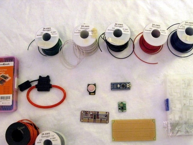
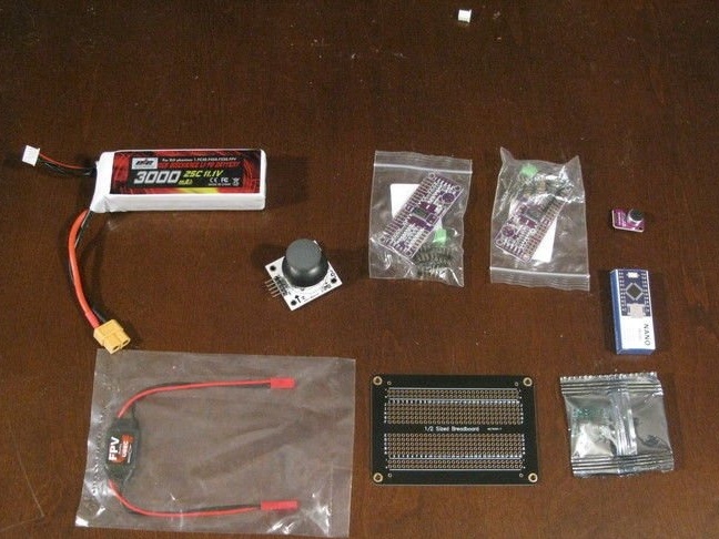
-Arduino Nano;
-7.4 V 850 mAh LiPo battery;
-XT30 connectors;
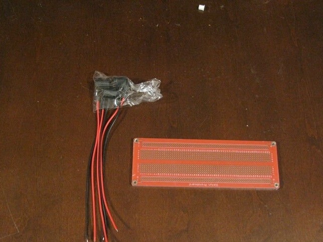
-Fuses with connector;
-Button switch;
-Charger;
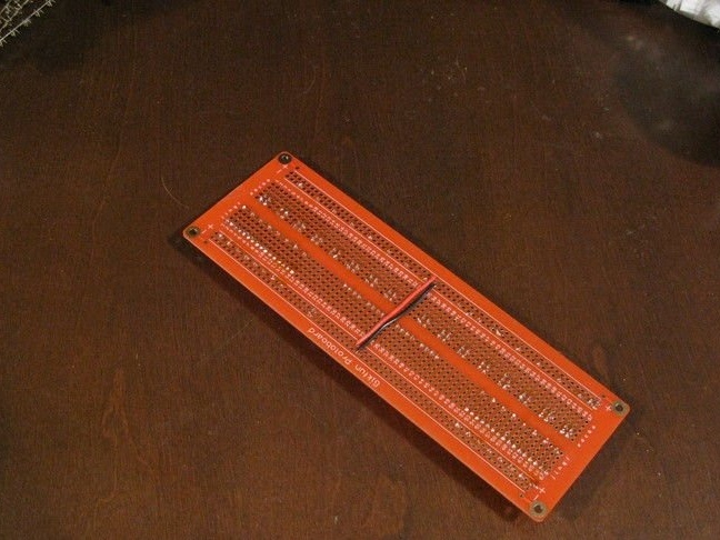
-Bread board;
-Connectors;
-Wire;
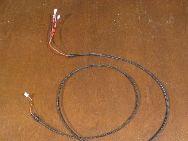
-Cable braid;
-Shrink tubes;
-Hair dryer;
-Fasteners;
-Black acrylic sheet;
-Board;
-Laser Cutter;
-Rivets for clothes;
- Velcro;
-Scissors;
-Cable ties;
-Cable clamp;

Step one: design, diagram
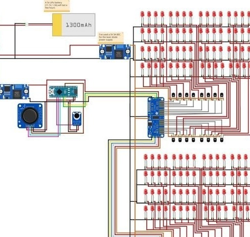
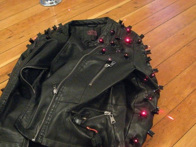
The main idea is to fix 128 laser diodes on the jacket and provide power and control of the laser diodes electronically. Electronics It is installed in the case and hides under the lining together with wires. Joystick and microphone are used for input. Power is provided by a LiPo battery.
Also, the master brought the electrical circuit. It should be borne in mind that ordinary LEDs are indicated on the circuit, and laser diode modules have their own internal circuits, therefore they do not need resistors to limit the current, as is usually the case with LEDs.
Step Two: Laser Modules
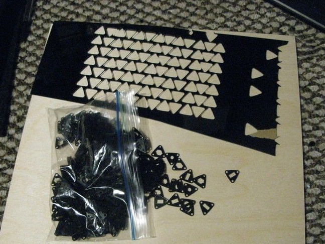
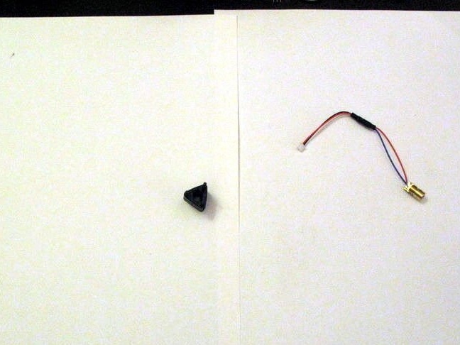
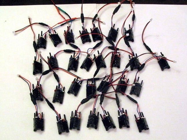
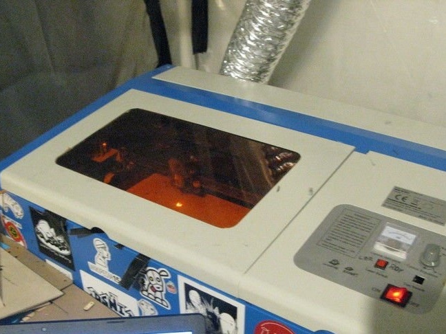
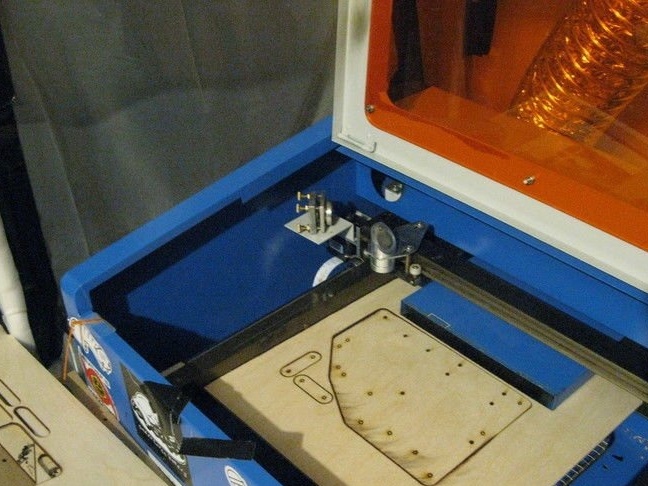
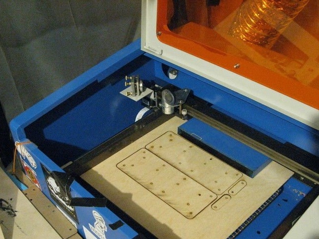
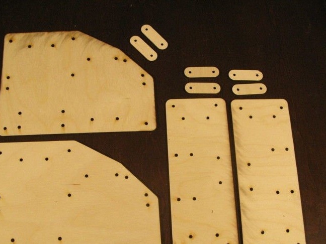
Laser modules are mounted on jackets in specially made holes. The modules themselves are installed in black acrylic cases made on a laser cutter. You can download the file for making the case.
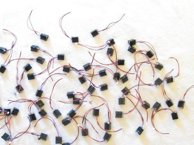
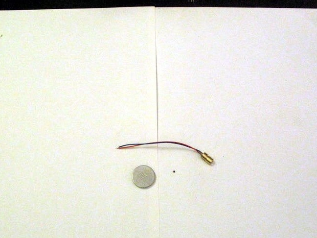
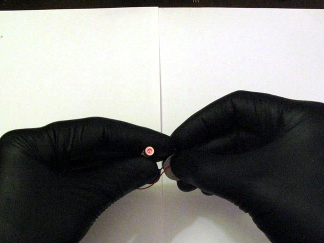
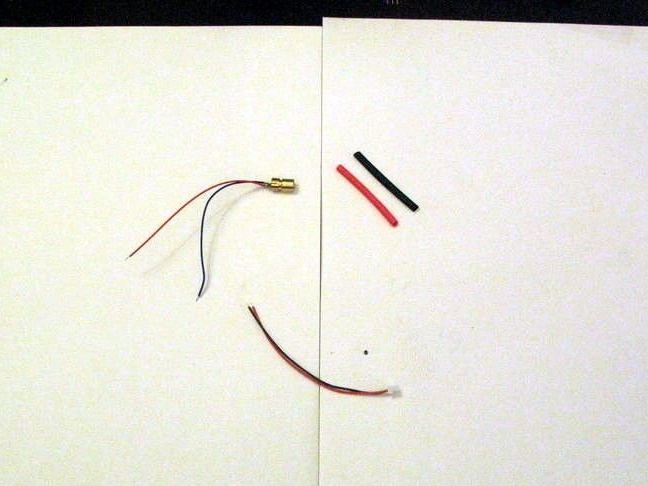
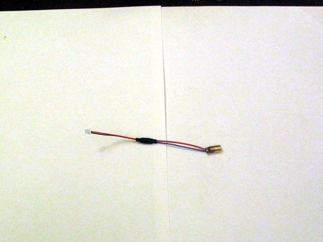
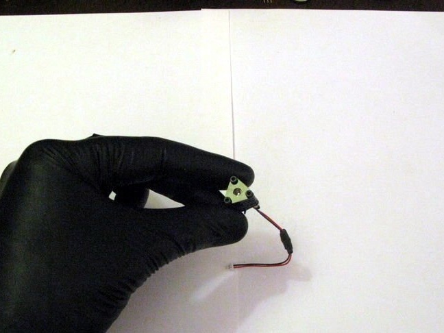
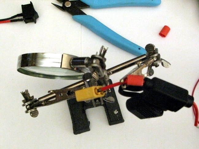
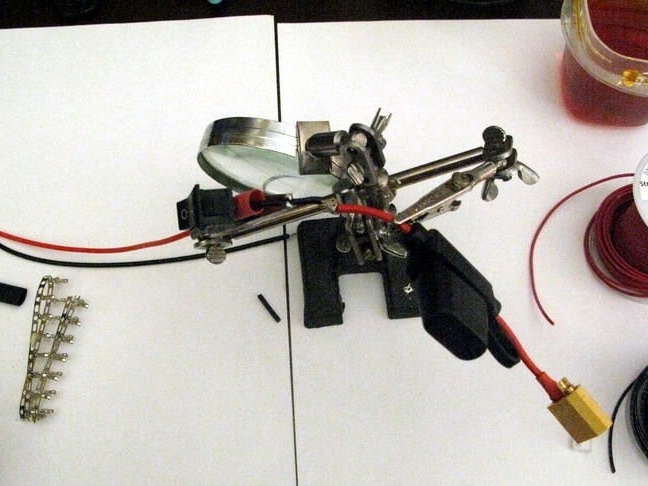
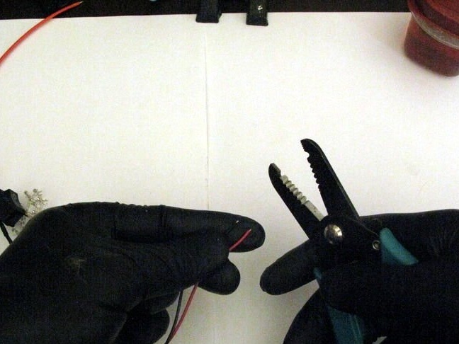
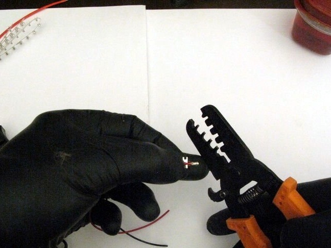
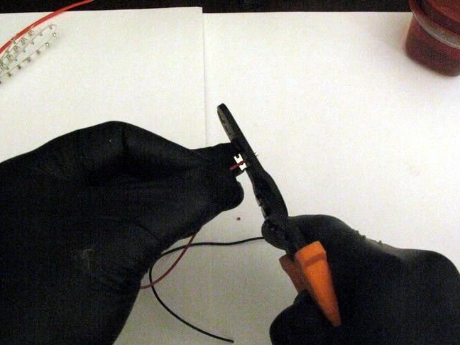
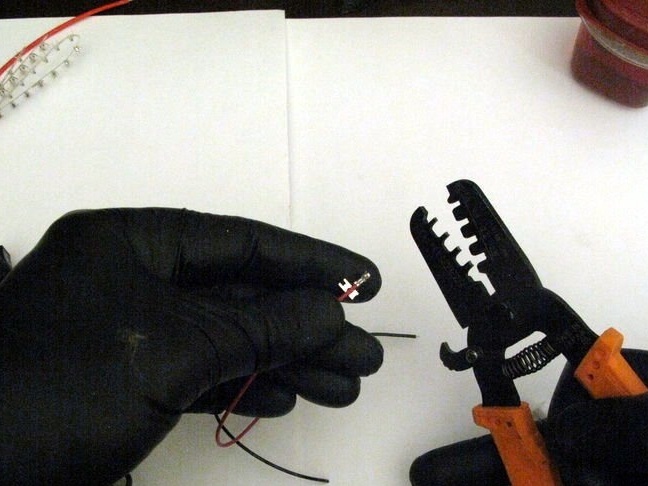
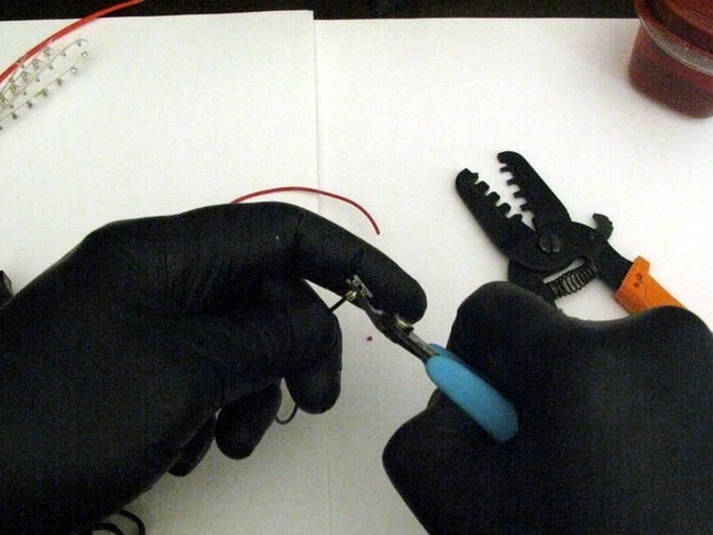
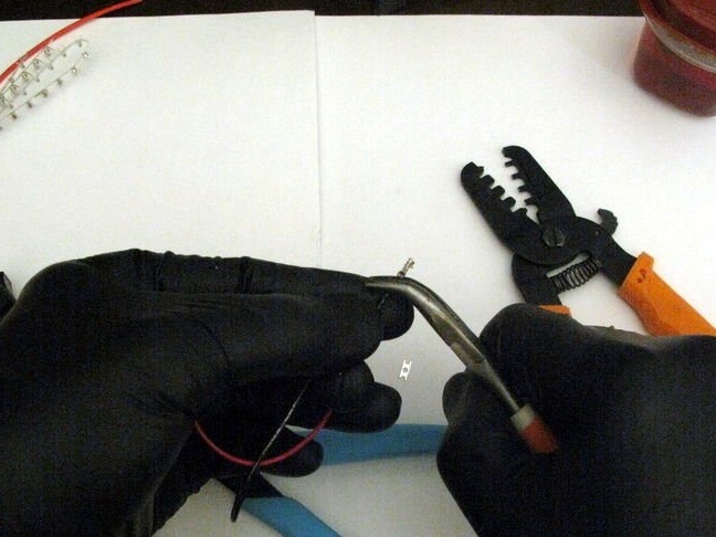
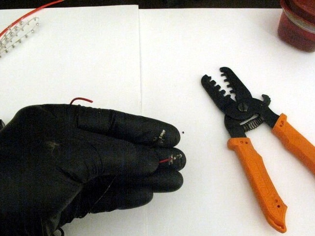
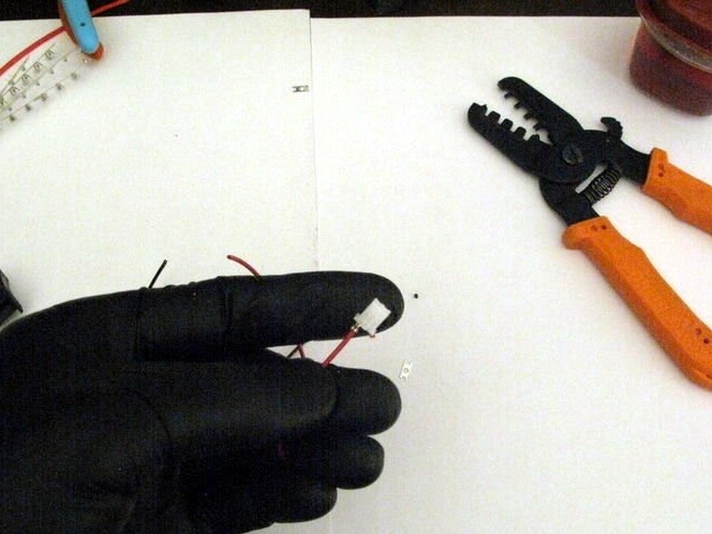
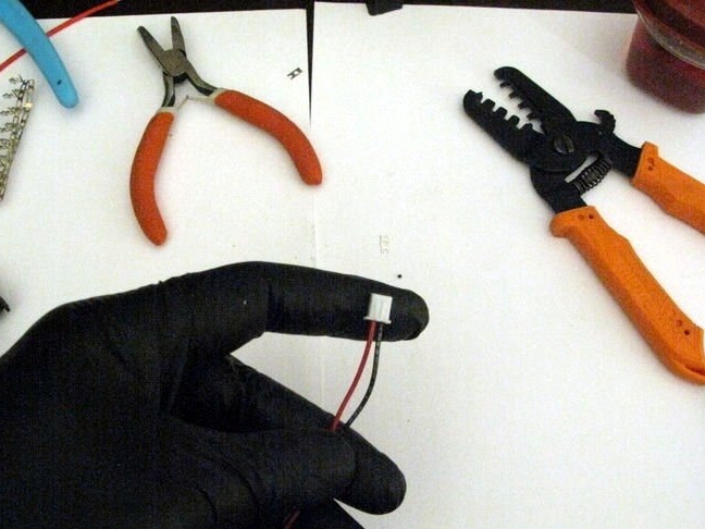
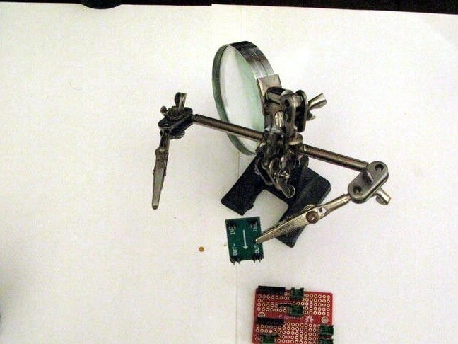
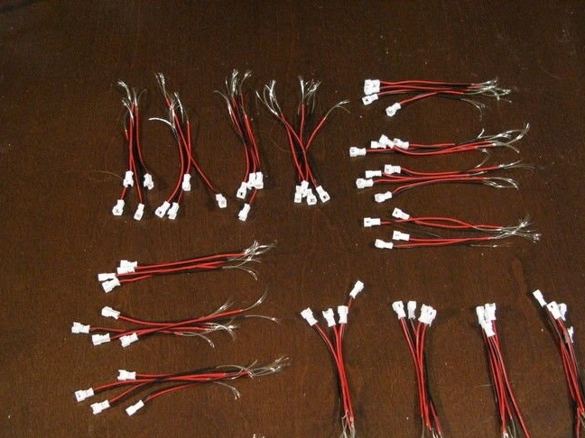
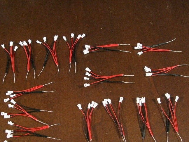
Before assembly, you need to check each module and solder the connectors to the wires.
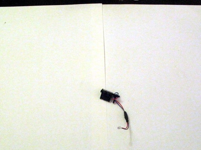
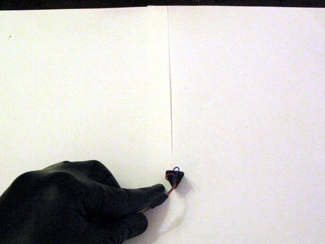
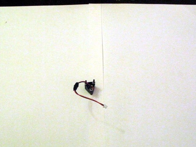
Now you can install the laser modules in the housing. The housing is secured with screws and nuts.
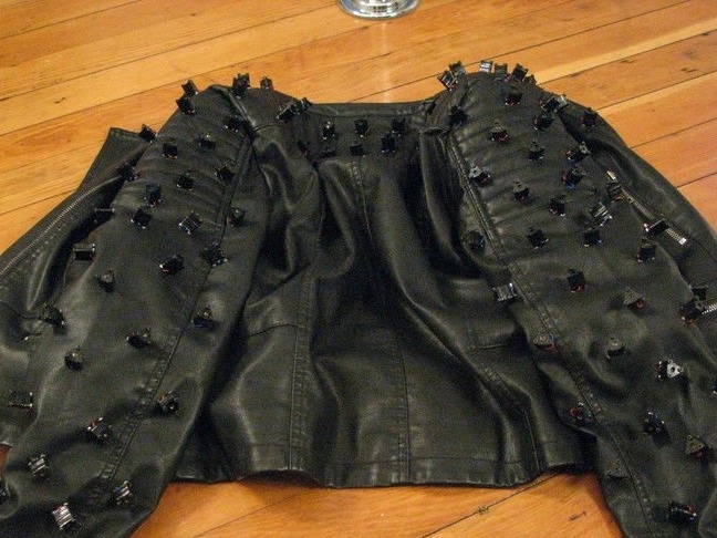
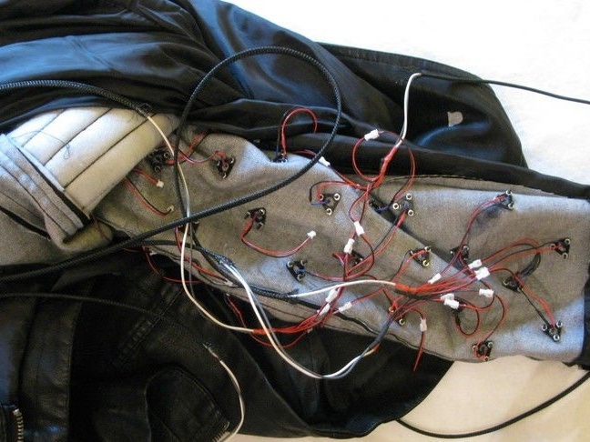
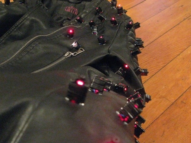
Step Three: Mounting the Diodes on the Jacket
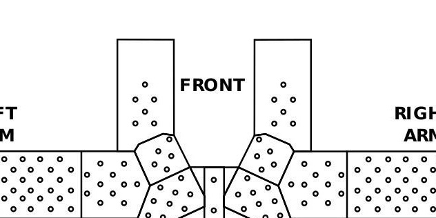
For the correct location of the laser diodes, the master, on the jacket, marks the places of their installation.
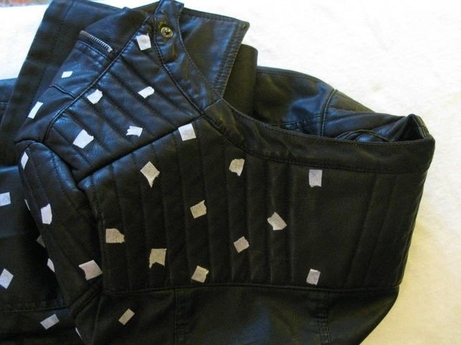
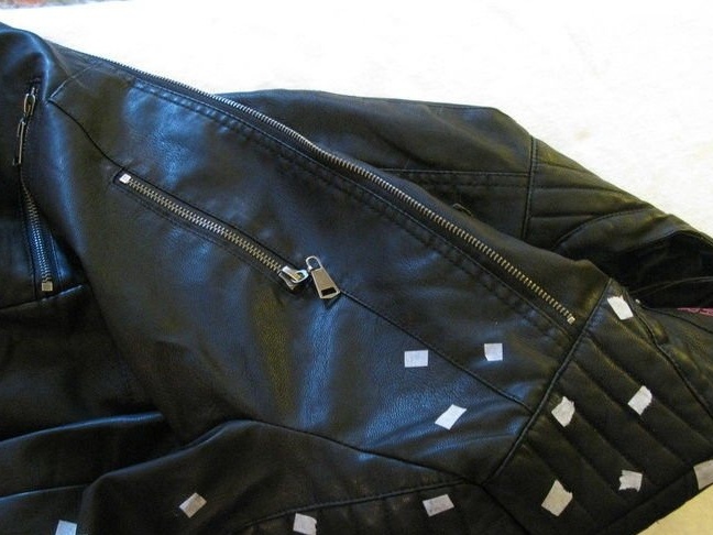
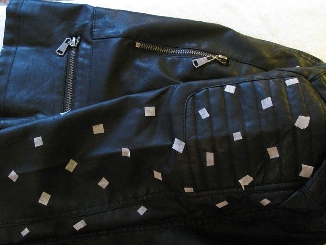
Further along the template marks and cuts out holes for screws and a diode.
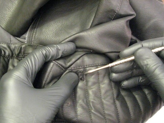
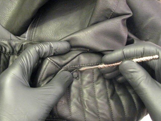
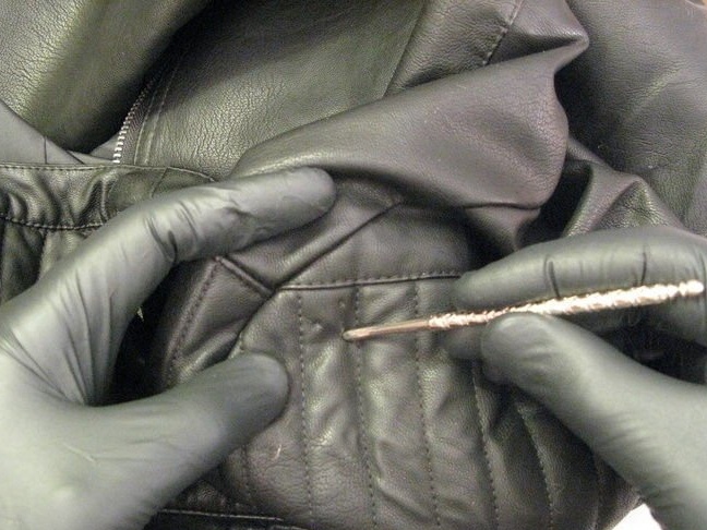
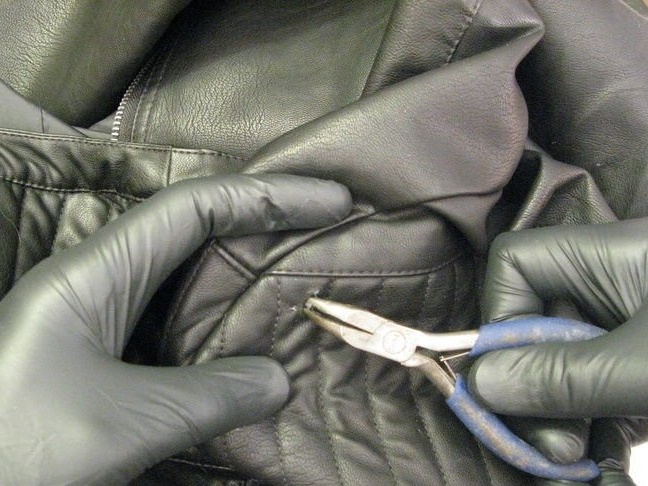
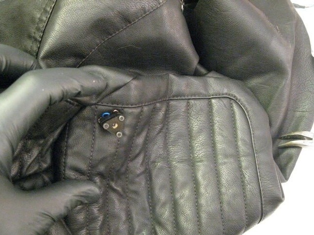
Installs the diodes in the holes, and on the back, on the screws, installs the plate. Tightens the nuts.
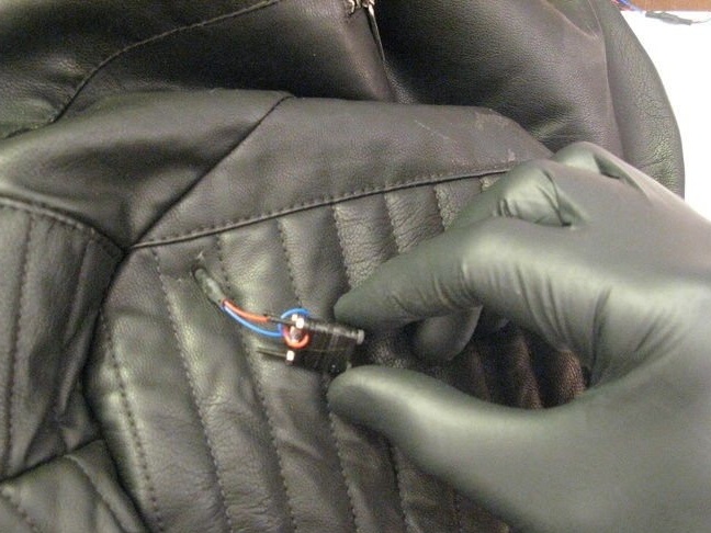
After installing all the laser diodes, the master advises once again to check their performance. If a malfunction is detected, repair it or replace the diode completely.
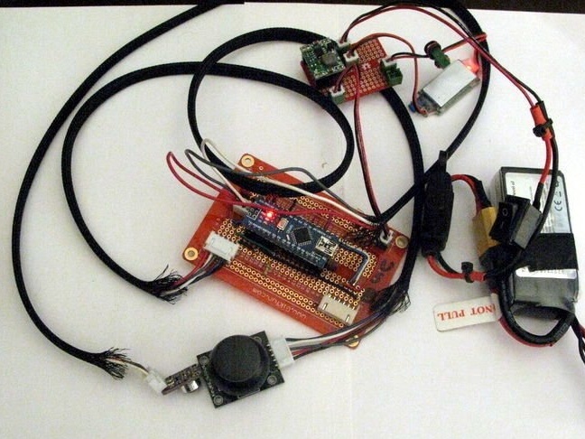
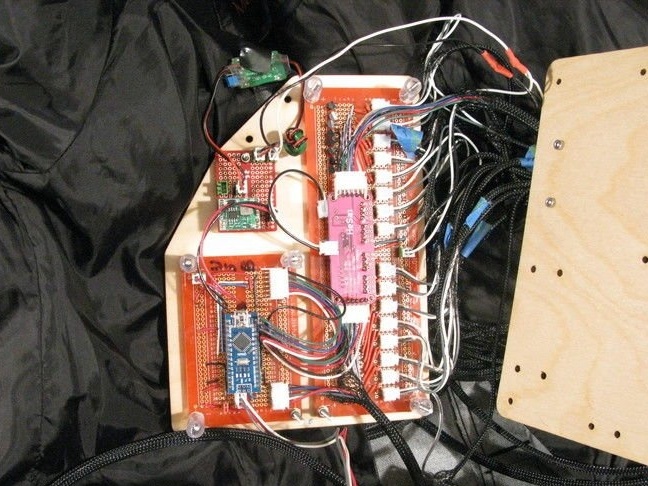
Step Four: Electronics
Electronics is a pair of PWM PCA9685 controllers that are Arduino Nano. A microphone is connected to the Arduino to input surround sound, such as music. Also, a joystick with a button is provided for control.
Currently, the wizard provides three modes:
Flickering - the light of laser diodes in the form of "flicker"
Graphic equalizer - diode control depending on the data received from the microphone.
Joystick control - use the joystick to directly control laser diodes. Each output line of the PWM driver is fed to four laser diodes.
Laser diodes are powered by 5V 3A. Arduino Nano and all peripherals are powered by a 5V buck converter. The BEC and the buck converter are powered by a LiPo 2s battery. The battery has a 3 A fuse and a power switch.
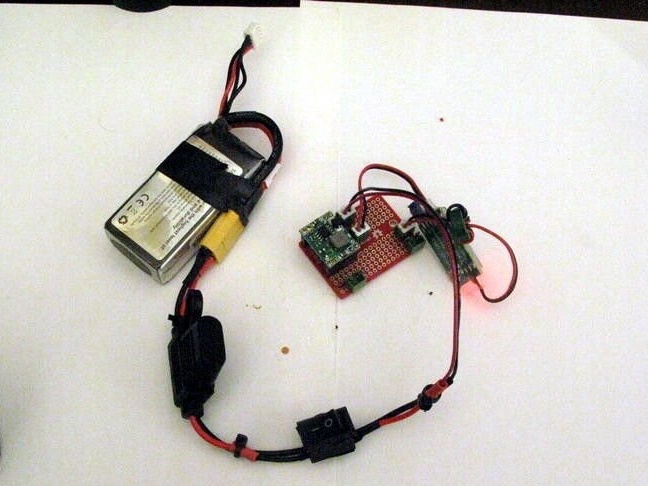
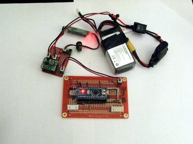
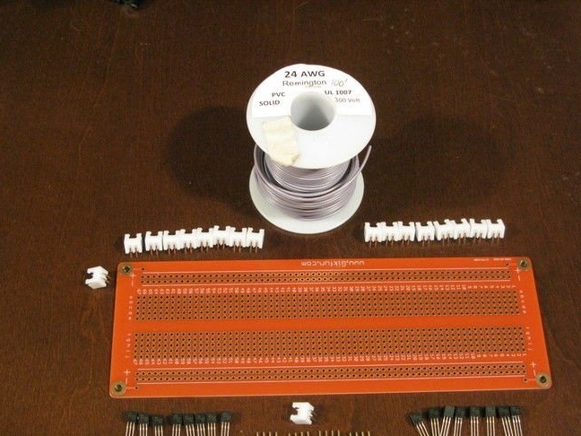
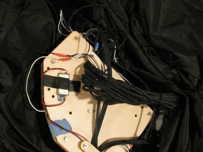
Step Five: Battery and Buck Converter
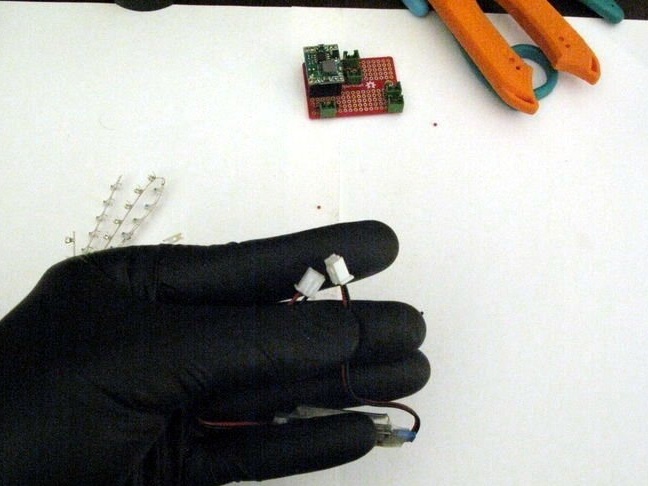
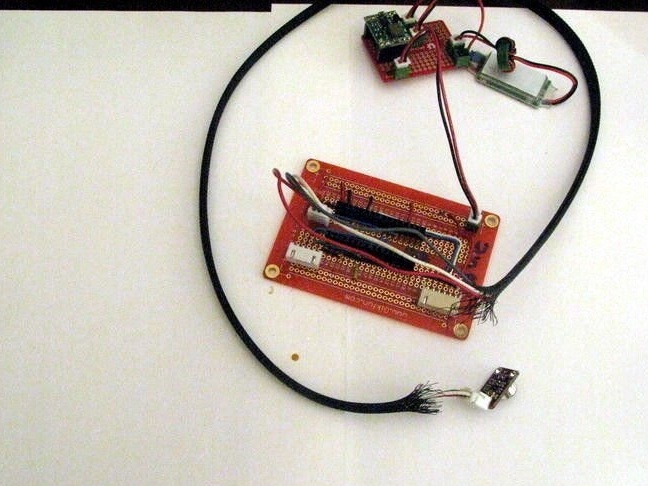
Next, the wizard begins to install the circuit. Mounts, after battery, connector, switch and fuse. Isolates joints with a heat pipe.
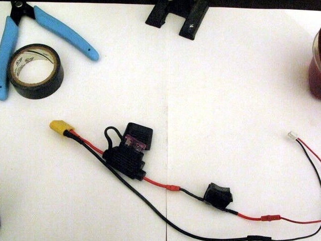
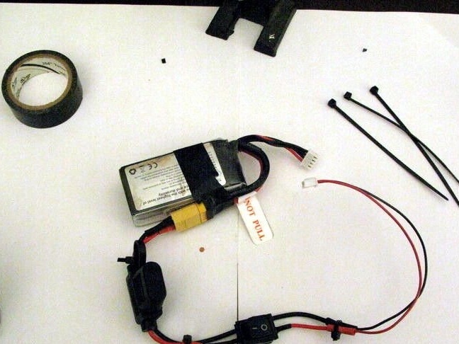
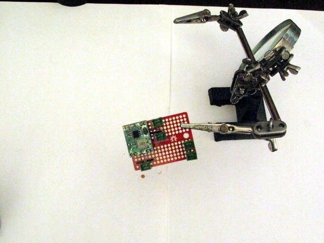
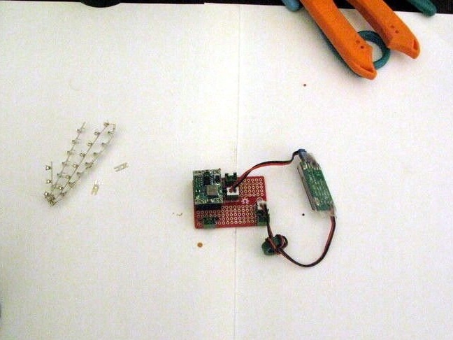
The lowering module mounts on the breadboard. Connects the stabilizer and battery. Checks the operation of the circuit.
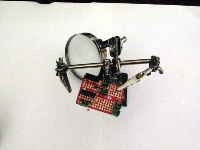
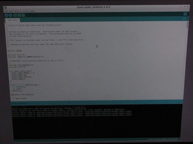
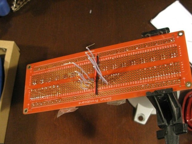
Step Five: Arduino
Mounts Arduino on a breadboard. Installs connectors on the board and connects to the corresponding pins on the Arduino board.
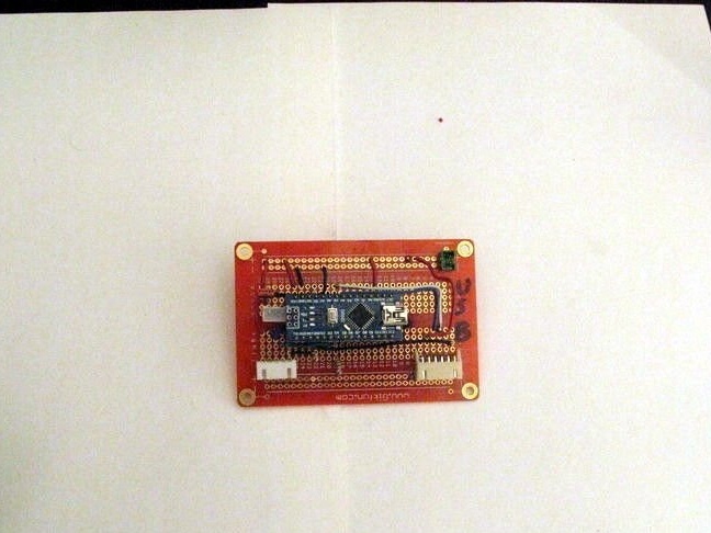
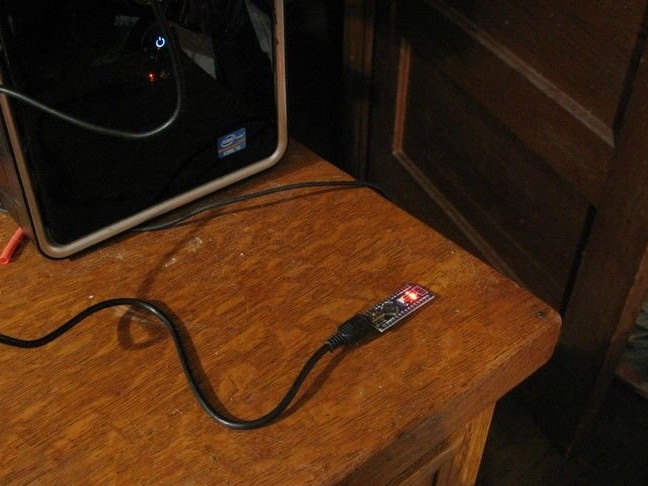
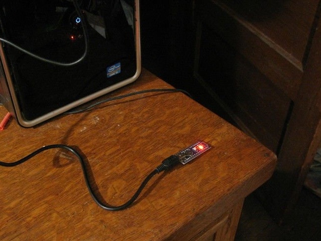
After installation, programs Arduino. Installs and.
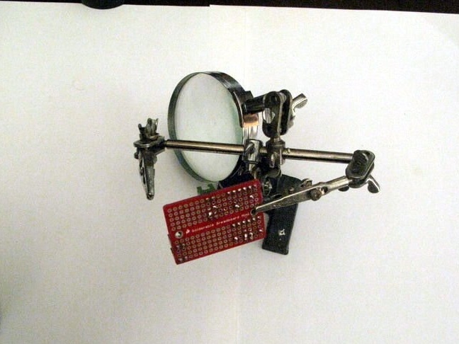
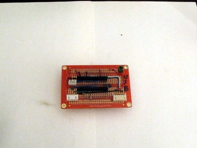
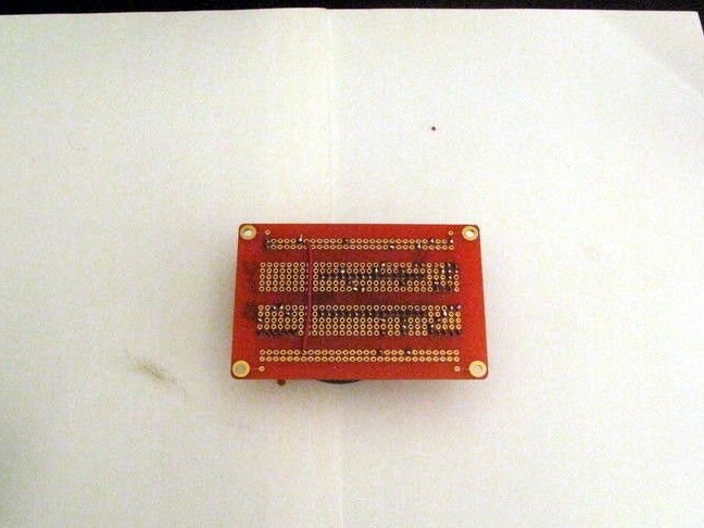
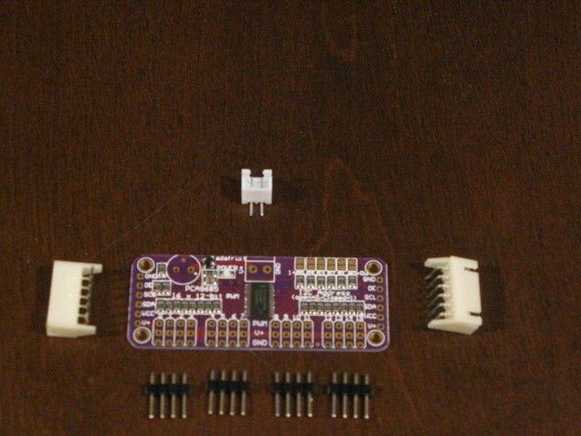
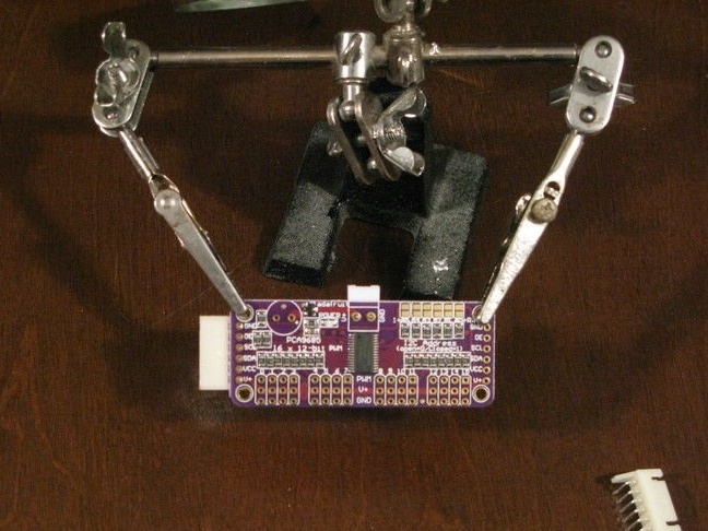
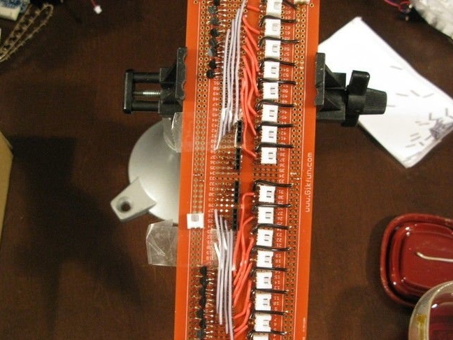
Step Six: PCA9685
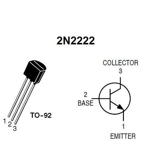
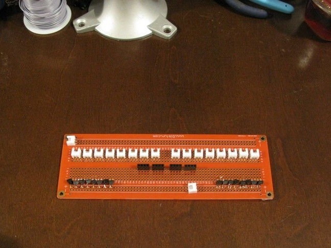
Further, according to the scheme, the controllers are mounted. Controllers are mounted on Arduino using connectors. A 2n2222 transistor is installed in the circuit between the controller and the laser diodes. Each PCA9685 PWM controller has 16 outputs; accordingly, transistors must be installed on each output.
The line from the 2n2222 transistor is used to power the laser diode through a 2.5 mm JST female connector.
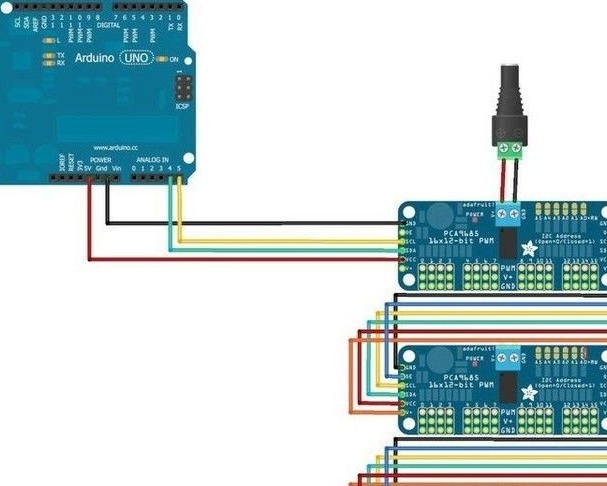
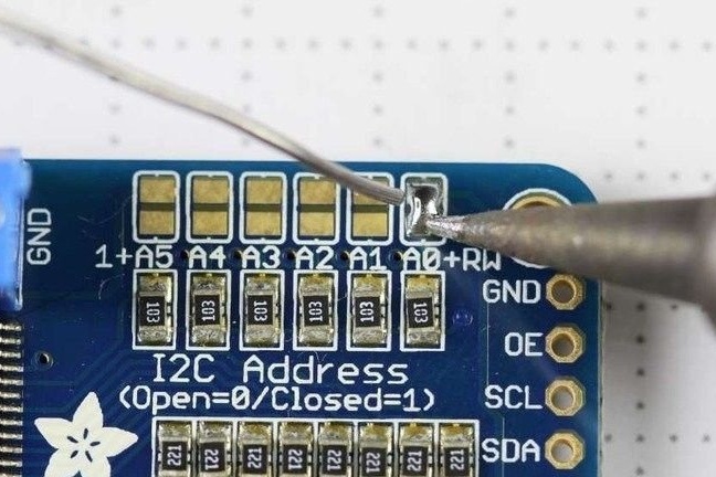
There are two PWM controllers in the circuit that control their group of laser modules. For their independent management, you need to rename one of the modules. By default, they are both defined as 0x40. This can be done by setting a jumper on pin A0. In this case, the address changes to 0x41.
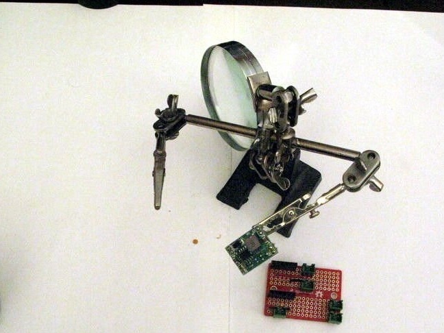
Now you can mount on a breadboard.

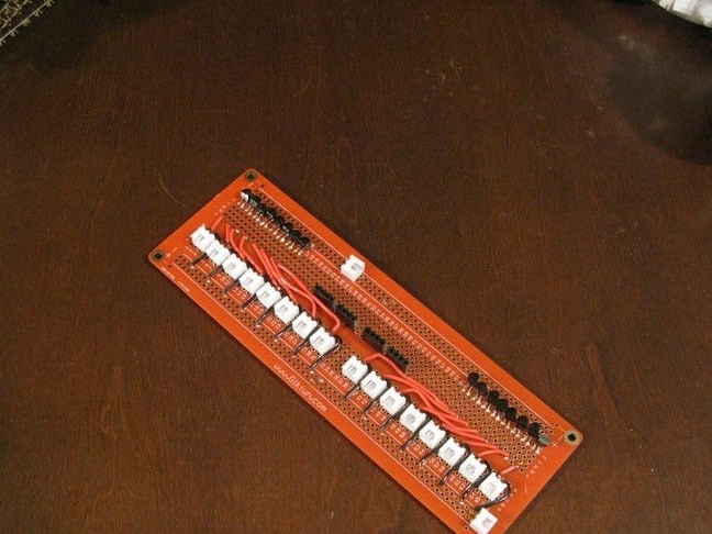
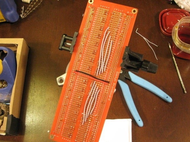
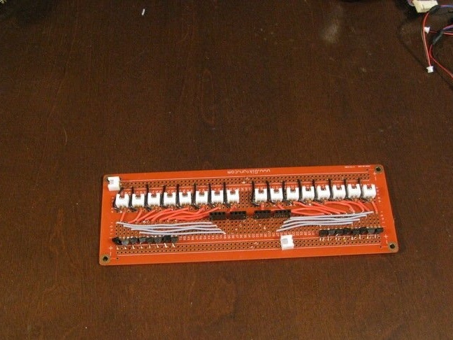
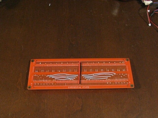
Next, the master makes the wires to connect. Installs connectors. Combines them in 4 (4X1 = 64 for each PWM).
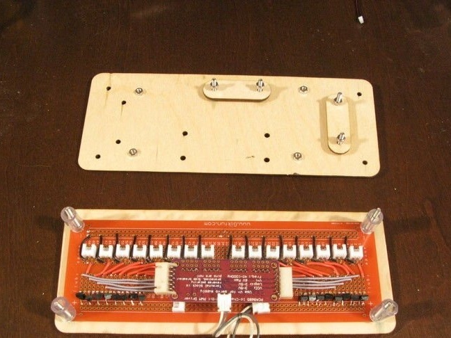
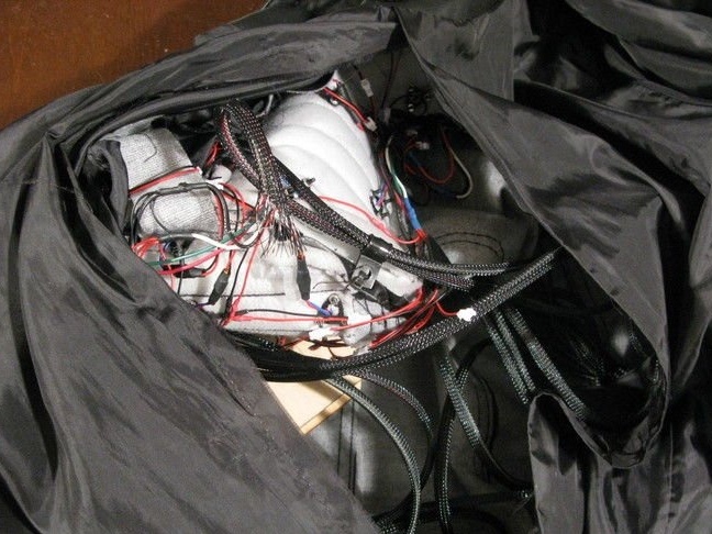
Seventh step: assembly
Next, the master connects the connectors, secures the board, tests the device’s performance.
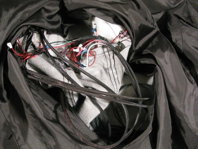


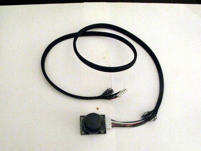
Connects a joystick and microphone.
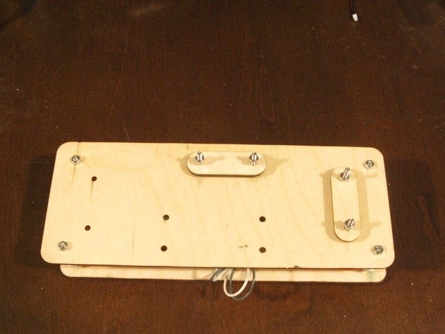
Installs electronics in a case cut out on a laser cutter.
.

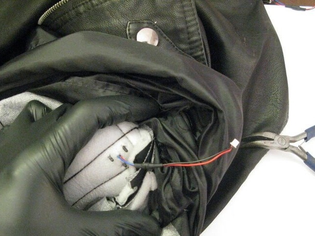
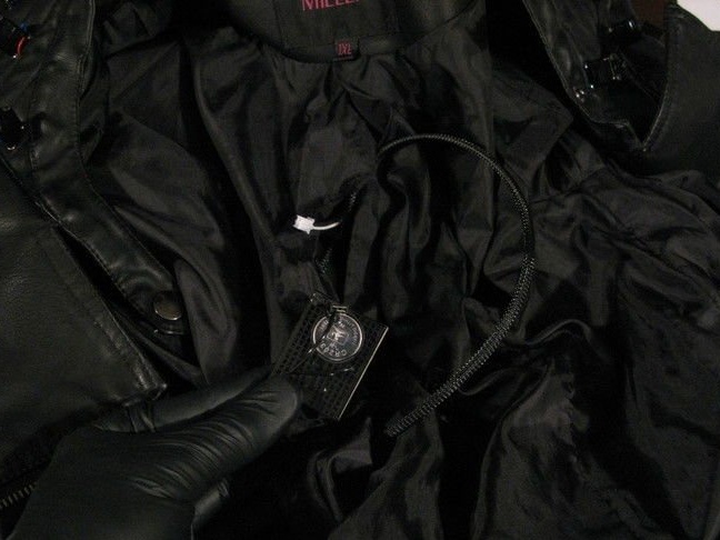
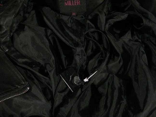
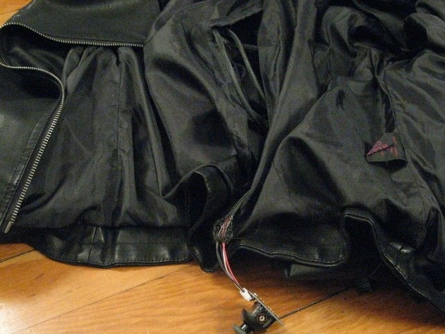
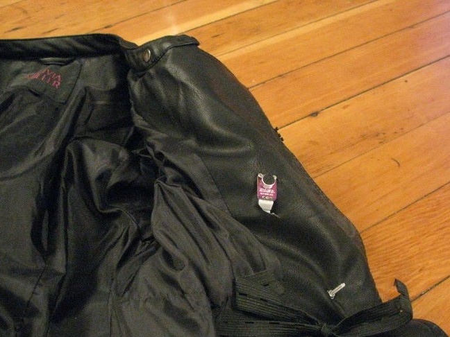
Sets the case under the jacket lining and firmly fastens.
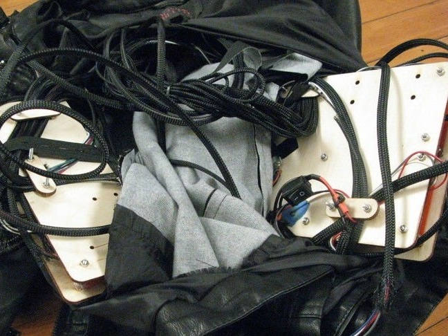
The microphone is brought out. The joystick is set at palm level. After assembly, the lining is fixed with Velcro.

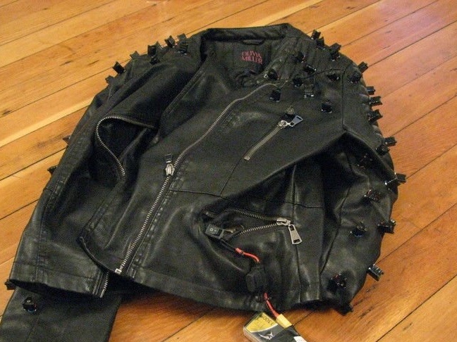
Jacket with laser projection is ready. It remains to put it on and test it.