Background:
On shelves with spare parts for electronics, 3 different computer speakers were gathering dust, with split cases and torn wires, but the amplifier boards and speakers were working.
The first amplifier (4w x2) had good sound at medium and especially high frequencies, as well as had a bass-treble tone control, and volume control.
The second amplifier (3w x2) it sounded great at medium frequencies, while it had a “stereo widening button” and volume control.
Third amplifier (15w SUB + 3w x2) was from a kit with a subwoofer and two tweeters giving out good bass, it also had a volume control.
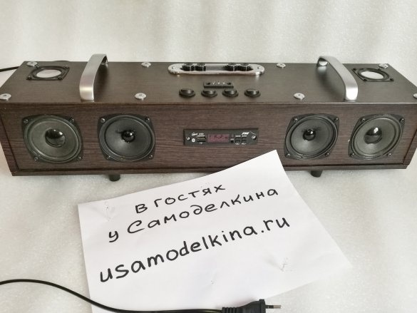
For a long time I wanted to collect hi-fi MEDIA CENTER from all this “wealth” in a monoblock (not a “boombox”, with volume the main priority) with good sound quality, the heart of which would be bought (on the famous site of the Chinese brothers) "USB-Bluetooth-Radio module."
Used in work:
Laminated fiberboard 2100 × 150 (1 pc.)
Laminated fiberboard 2100 × 100 (1 pc.)
wood glue (preferably bone)
glue gun and glue to it
corners 15 × 15 (15 pcs)
3 × 5 screws
hairpins M6 × 100 (8 pcs)
end sleeves (nuts) M6 with a deaf cap under a hexagon (16 pieces)
power wires
speaker wires
signal wires
heat shrink tube (different)
soldering iron
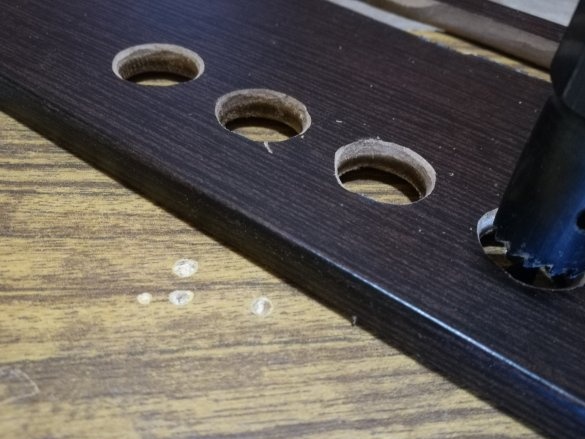
wood crowns (diameter corresponds to the speakers) D67, D50, D30
thick cardboard tube for D30 / L60 bass reflexes (3pcs)
network cable + jack for it
telescopic antenna L150 / 400 (1 pc.)
LEDs (3pcs)
decorative handles, for potentiometers (resistors) (4pcs)
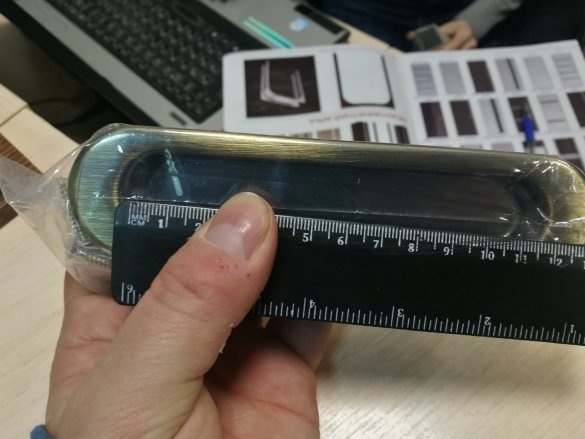
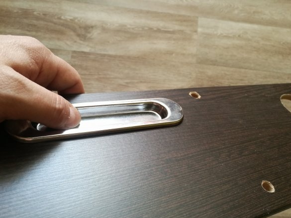
mortise door handle (for swing doors) L150 (1pc)
handles for the cabinet arc-shaped L130 (2pcs)
plastic support legs L20
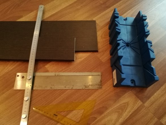
MDF miter box and hacksaw
synthetic winterizer
step 1.
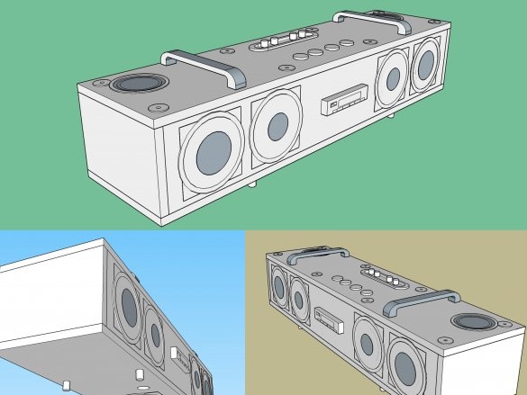
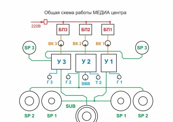
We model the layout in a 3D editor, draw a general scheme of work
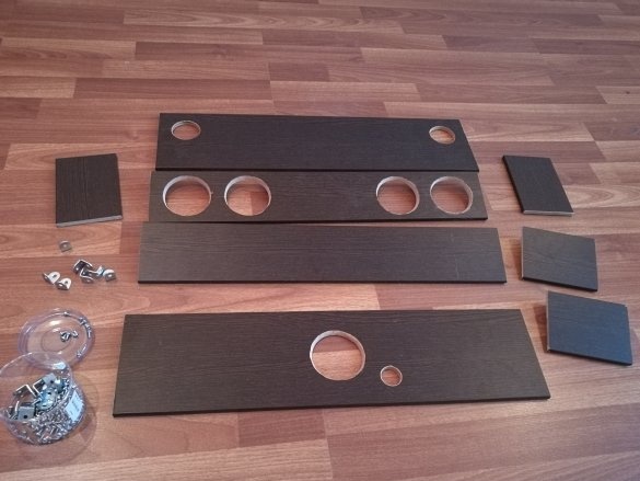
We mark and cut off the blanks (reference dimensions, since each will have everything individually)
a) top, bottom = 600 × 150 (2pcs)
b) front, back = 584 × 100 (2pcs)
c) ends = 100 × 150 (2pcs)
d) bulkheads = 100 × 180 (2pcs)
step 2.
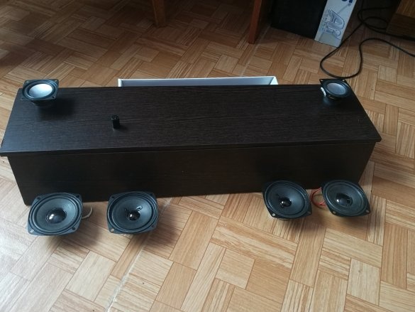
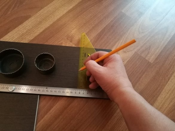
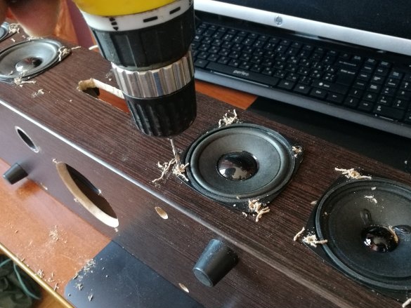
Marking holes for speakers
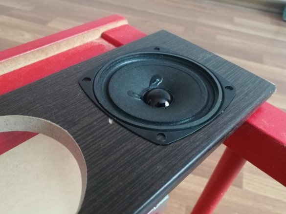
4w x2, 3w x2 - on the front (front) part of the body
15w SUB - on the bottom of the chassis
3w x2 - on the top cover of the case
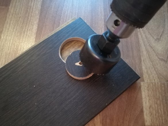
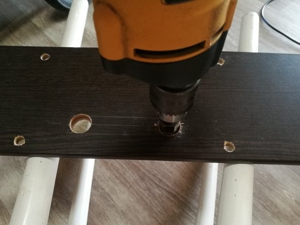
Drill a hole with a crown
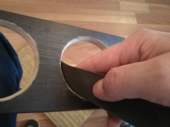
We process sandpaper
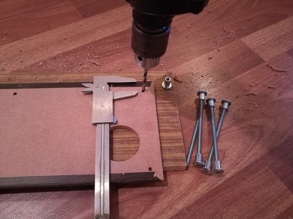
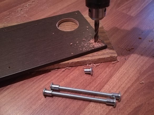
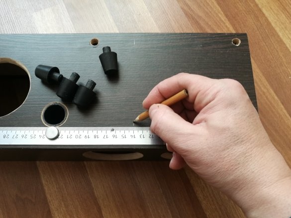
Mark and drill holes for screeds with studs
step 3.
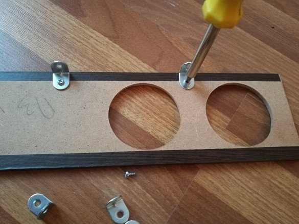
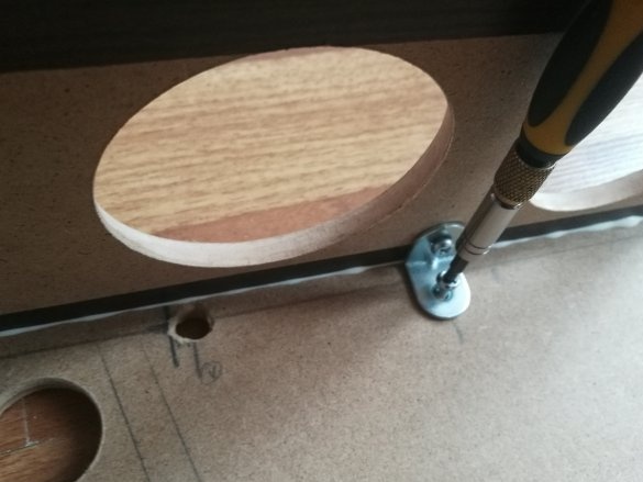
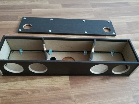
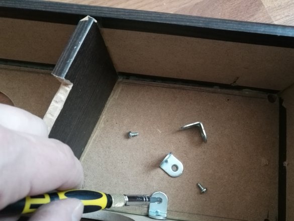
We assemble the box, temporarily turning the corners, to fit the parts of the case
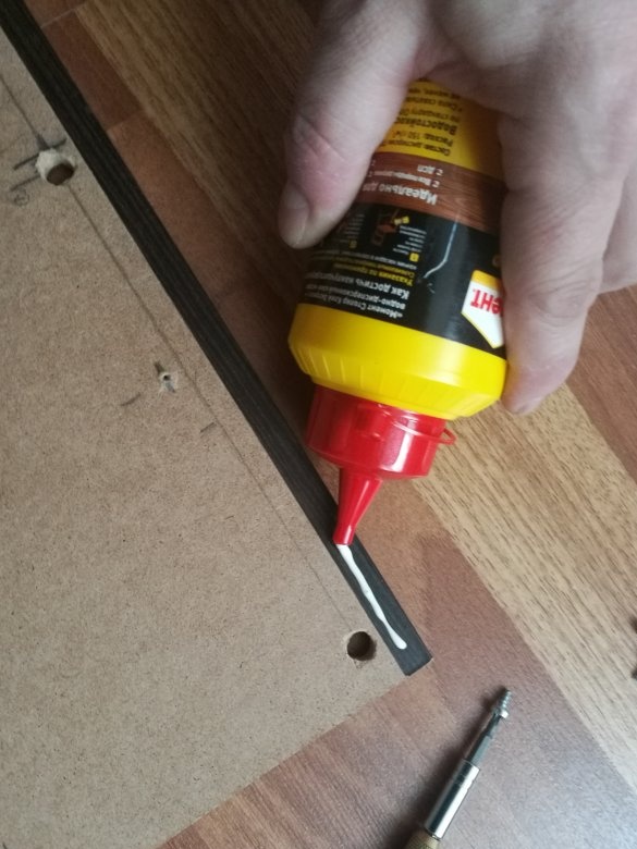
removing panels alternately - coat with wood glue and tighten with corners
In bulkheads, we make recesses for pulling wire harnesses
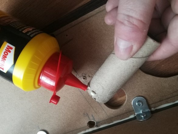
Glue the subwoofer bass reflex tube
We are waiting for the glue joints to completely dry, and we turn out the screws and remove the corners
step 4.
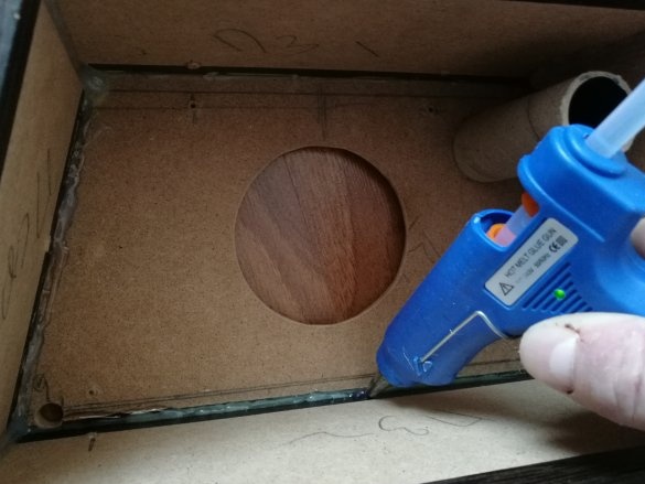
With a glue gun we pass all the seams (creating additional mechanical strength of the joints)
Trying on speakers
step 5.
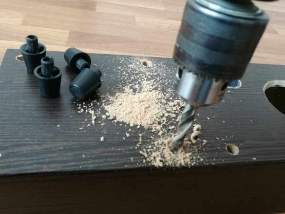
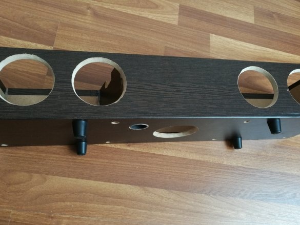
Mark and drill the holes of the support legs (needed for the normal operation of the subwoofer speaker)
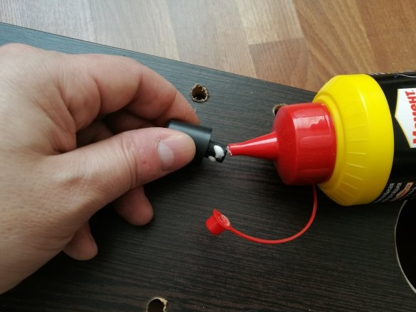
Glue the legs to the carpentry glue
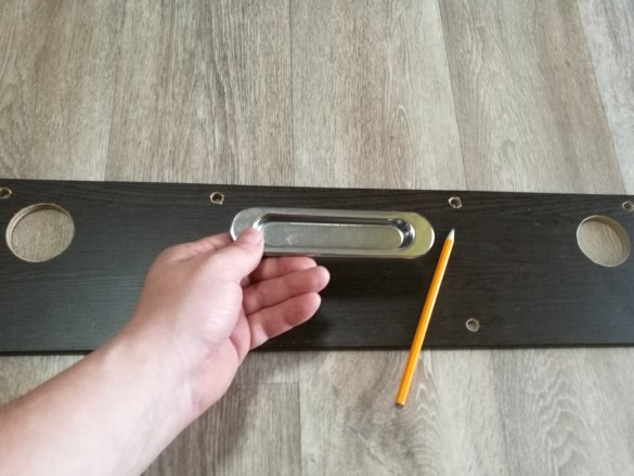
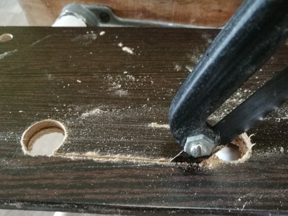
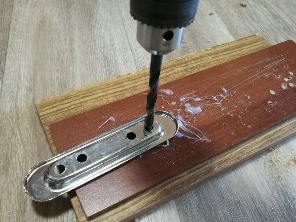
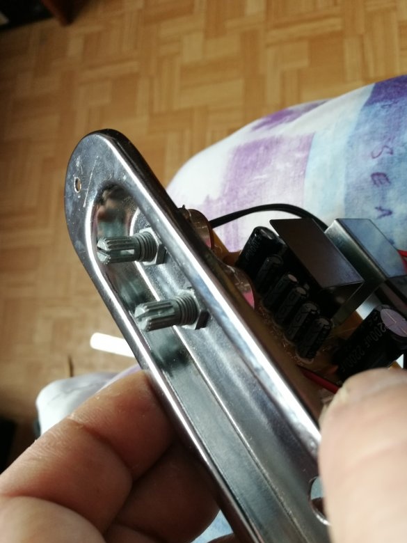
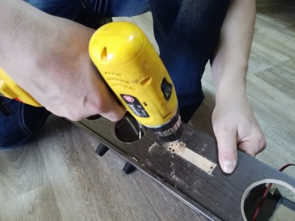
We mark and drill a groove for the door handle, which performs the function of a niche, for placing the knobs ("twists") of potentiometers.
We mark and drill 4 holes in this handle to accommodate potentiometers.
step 6.
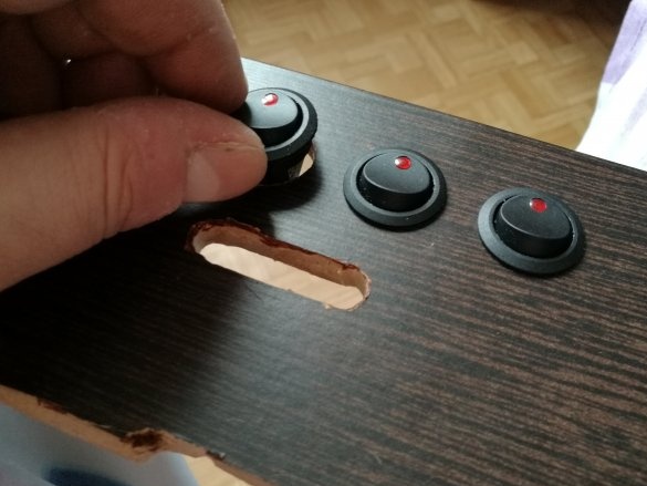
For perfect tuning of the sound field, it was decided to maintain the separate functioning of each amplifier, so there is a separate switch for each amplifier (as well as a “stereo expansion switch”)
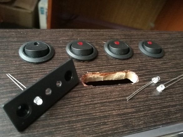
We mark and drill holes for all switches, as well as a common network switch, on the rear panel.
Cut out the groove for the power cord jack.
Step 7
We begin to collect in a single whole electronic stuffing MEDIA center.
We set the switches in the upper deck, and the potentiometers in the prepared decorative knob.
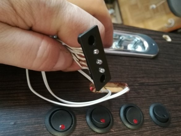
We solder the LEDs, and place them in a suitable plastic part (I used a part of the fastening of a children's toy)
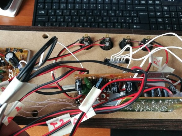
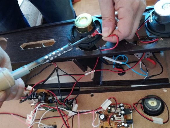
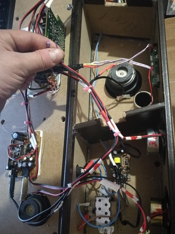
We connect the wires, marking the wires with paper tape and making marks on it with a marker (this is necessary, for example: to transfer acoustic wires if you mixed up the left and right speakers)
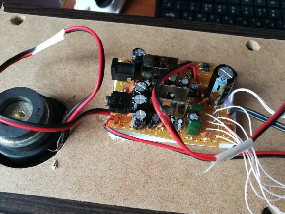
We solder the speakers, amplifier transformers - we fix on the bottom of the case.
Step 8
The first two amplifiers were fixed directly to the decorative handle, with potentiometer nuts.
Subwoofer Amplifier - was removed and fixed to the upper part of the housing cover.
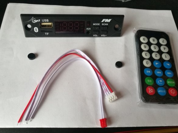
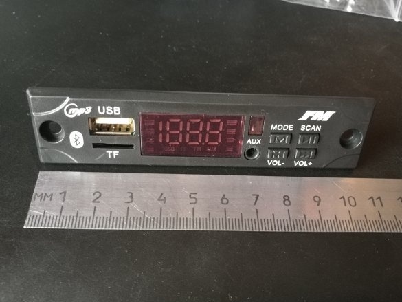
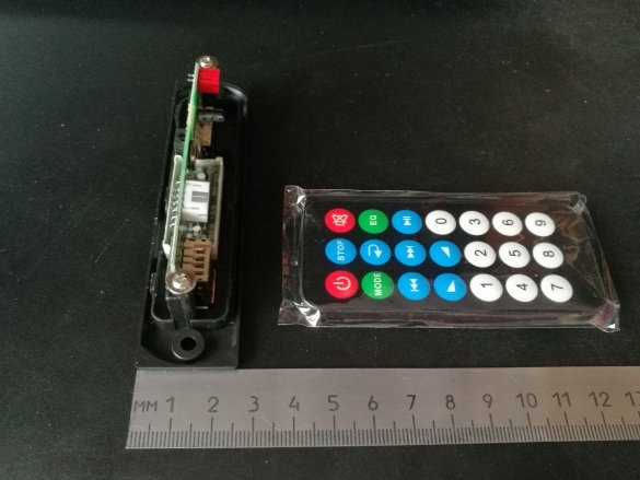
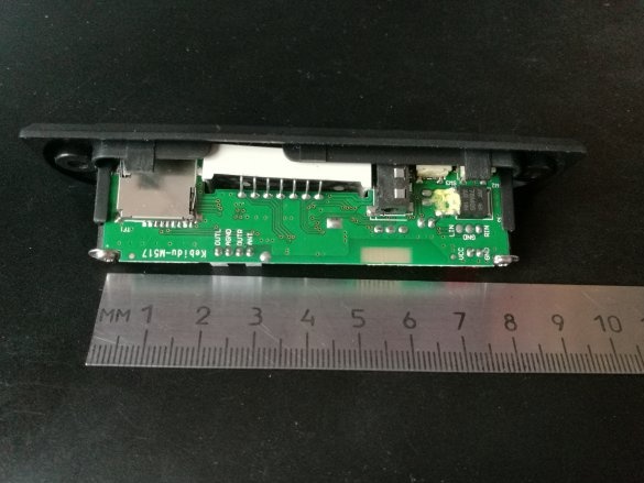
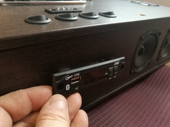
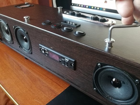
At this point, a wonderful USB module from ChinaWhat it has: USB port, TF port, Radio, Bluetooth. power supply 5-12v
The location of the module was chosen on the front of the case.
We mark and drill a groove for it.
Step 9
Signal incoming channels of three amplifiers - connect in parallel to each other, and solder to a set of wires with a connector, "arrived" with the USB module
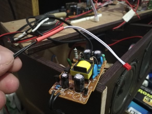
We fix the power supply for the USB module (I had it ready for 9v, but it can be ordered on"The same well-known site", together with the module)
We check all the connections and the correct location of the speakers and record a special track with separate sound on the flash drive.
On the bulkheads, in the grooves made, we fix the vibration-suppressing madeleine (through which the wiring harness will pass)
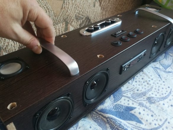
In the upper case cover - mark and screw the handles for carrying the MEDIA center.
Step 10
After listening to the “pre-assembled design”, I realized what I needed to add.
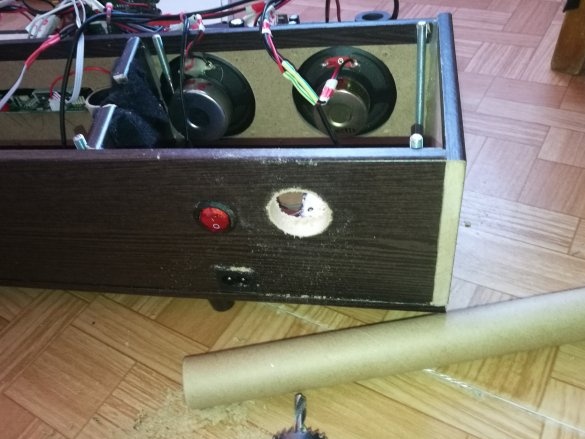
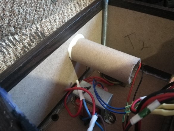
Two additional bass reflex tubes (in the left part of the case and the right) were marked and cut into the back of the case, as well as the subwoofer section was filled with syntepon. The sound after the operations became "crystal clear" and having a pronounced sub-bass color.
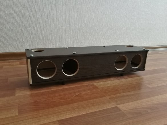
We tighten the body with studs, wipe it from dust.
Total
We enjoy high-quality sound, devoid of flaws, which can be adjusted to suit every taste and music genre
here you can see how it works
Thank you for reading about the end!


