
For measuring and fixing in time on flash memory of long processes expressed in current and voltage, such as charge - discharge of batteries and batteries. It is possible to simultaneously fix the temperature.
Input signal parameters:
current I = 25mka - 2a
voltage U = 0 - 5V
temperature t = -30 - + 120gС
time is set by the internal built-in quartz watch
Nutrition:
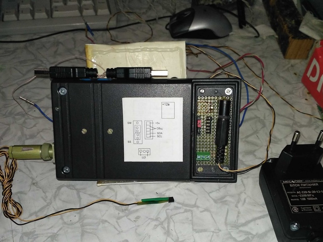
from the source 12v / 0.3a
I consumption <70ma
Design:
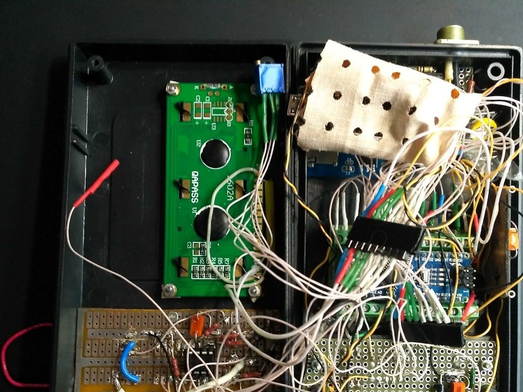
The meter is assembled on two modules Arduino Nano connected via ModBus protocol, see diagram. One Arduino is mounted on a riser with terminal blocks. The modules are connected via connectors. The wires and the modules themselves are insulated from thermal-cambric faults.
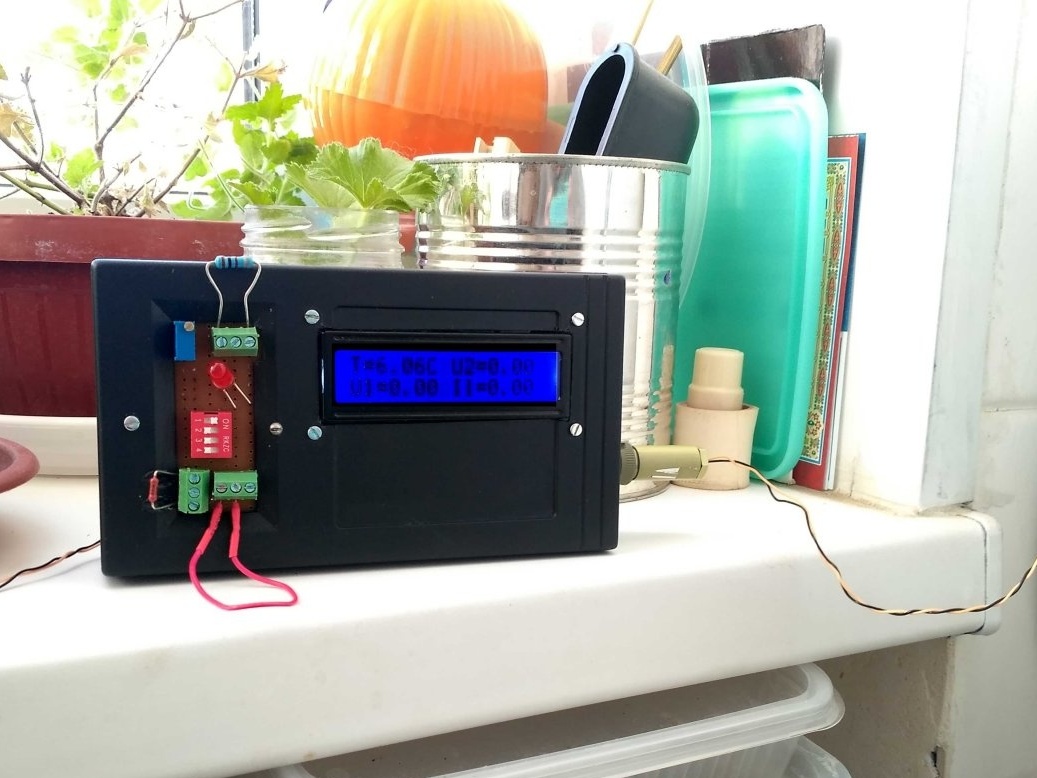
Input signals are fed through screw terminals
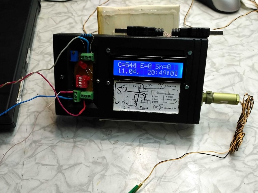
On the front panel there is a liquid-crystal indicator of the measured parameters and LEDs indicating the switching of a range or out of range.
The meter is assembled in a housing 145x85x40.
The temperature sensor is carried out through the connector. Signal transmission is organized on a two-wire line. Feed resistor in the connector.
For ease of programming, Arduino USB connectors are external.
Scheme
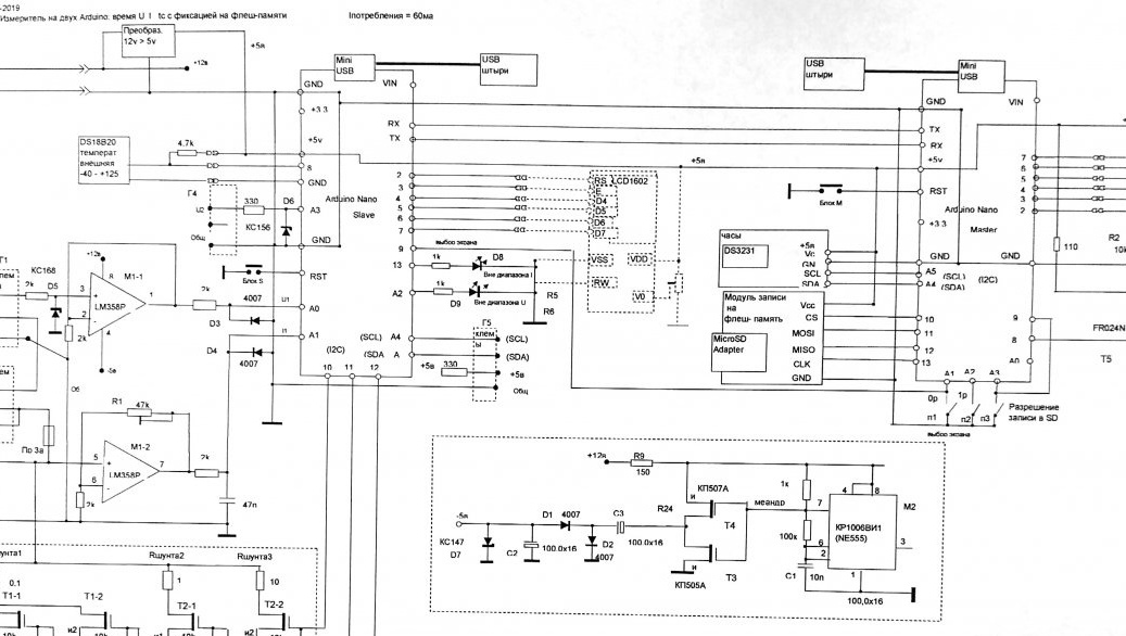
Scheme can be downloaded from file Meter.rar
Two Arduino were chosen for two reasons: Arduino Nano were available and not enough on one memory, and it is planned to add sensors further. In addition, I wanted to master the Arduino association, for this the ModBus network protocol was selected. ModBus defines one master processor - Master and several slaves - Slave. In this work, there is one Slave, on it is a measurement of temperature, voltage and current. On Master - a clock and a record to a file. Flesh memory must be less than 4GB and formatted in FAT.
Since it was planned to measure currents from μA to A, currents are measured in 4 ranges (see the Ranges table), the Arduino Slave monitors the transition from one range to another, forming the corresponding shunt code for the current measured current from M1-2. When approaching the border of the range, the next range is turned on, that is, the current key from T1-1 --- T2-2 is turned off and the next one is turned on. In this case, the maximum shunt = 100ohm is constantly on. If there is an excess of the value in the range, the LEDs D8, D9 are illuminated.
Dividing current measurement into ranges
Uout_max = 5v KusOU = 20 Δ = Ish / 1024
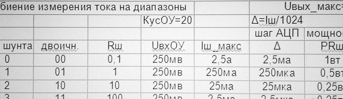
The gain of the operational amplifier M1-2 is set = 20 and then does not change. (On the front panel it is mounted erroneously).
The voltage is measured through a follower on the OU M1-1.The input circuits of the op-amp and Arduino are protected by diodes (zener diodes are in Arduino, but I don’t know the parameters, therefore it is better to overdo it).
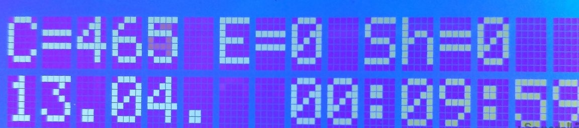
LCD1602 is selected as an indicator. It is connected to the Arduino Master. Moreover, the indicator can be connected to both Arduino simply by switching the Arduino connectors. (When the power is off.) The connection to the Arduino Slave is shown with a dashed line (which was used when writing programs). With the main connection (to the Master) on the LCD1602, you can display 4 screens by switching the slide switch slider p1-p2.
Screen1: from above the service information of the exchange between Arduino: C is the number of exchanges between Arduino, E is the number of errors during the exchange of Sh- No. of the shunt;
bottom day - month time.
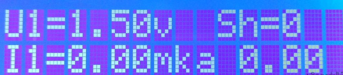
Screen2: U1, I1, Shunt No., (0.00 bottom right-reserve)
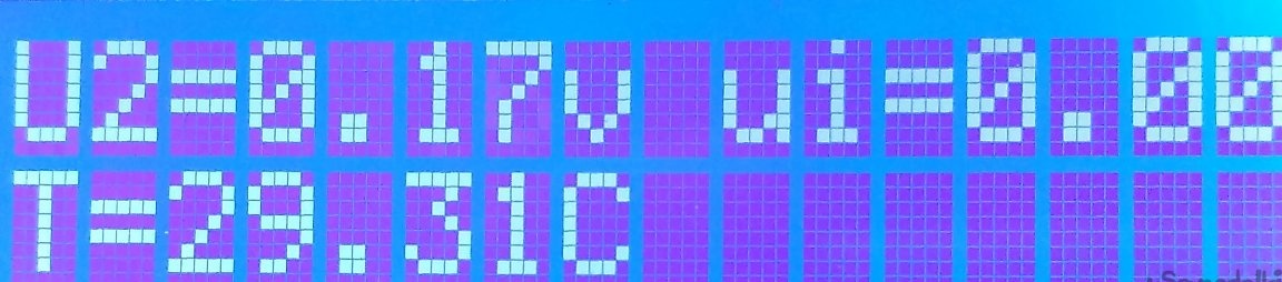
Screen3: U2, temperature, (ui- standby)
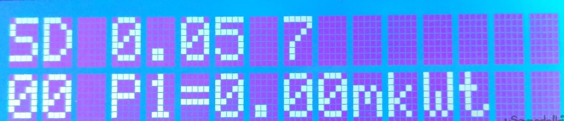
Screen4: SD recording enabled, recording time in hours, line number in file,
00- state of current range1 0-normal 1-out of range, state of voltage range1, fixed power of an external source
When connected to Slave - 2 screens. Switch p3 enables recording in Micro Flesh memory.
The power supply is selected 12v to obtain linear characteristics of the op-amp (to avoid blockages at the edges of the range). For the same reason, negative voltage from the shaper at KR1006VI1 was used. Using an Arduino generator produces a less stable voltage. To generate 5v power, a step-down converter was used, but you can do without it by supplying + 12V to the VIN Arduino Nano inputs.
Joint programming Arduino has features, since the communication with the computer is busy with the ModBus protocol. To load a sketch into one of the Arduino, on the other you need to enable the RST reset signal. To do this, use the jumpers Block S, Block M. Or press and hold the reset buttons on the Arduino modules until the download is finished, which is less convenient and there is a chance to damage the download. Since I plan to expand my USB Arduino device, I pulled the case out.
The transistor T5 (FR024N) is supposed to be used to turn on / off a process, for example, a charge-discharge of a battery. While it is not involved.
Software.
It is maximally chewed that beginners (and I myself) will not hurt and can serve as reference material, but do not claim to be optimality.
Libraries and program codes are located in the Izmeritel PRO.rar file.
Sketch for the master ModBus_Master10_SD_T_10_2. Sketch for slave ModBus-Slave10_T_UI_10_2. The rest of the library.
Programmed in the environment of Arduino1.6.0. It contains libraries SD, LiquidCrystal, Wire do not need to download.
The time in hours is set in Setup as follows. Set the real time and load the sketch. Then comment out the lines for setting the date and time and reload the sketch.
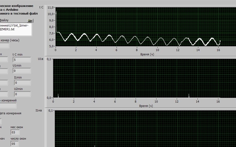
The result of the program will be the indication of time and date (hours), current, voltage, temperature on the LCD1602 and the recording of these parameters in the IZMER1.TXT file in Micro Flesh memory. The file will contain a table of this kind:
0; 04/13/2019; 00:11:10; Zap (h) = 0.05; tc = 29.31; U1 = 1.71; I1 = 0.00; P1 = 0.00; U2 = 0.14; DiaI norma; DiaU norma; C = 762
1; 04/13/2019; 00:11:16; Zap (h) = 0.05; tc = 29.38; U1 = 1.79; I1 = 0.00; P1 = 0.00; U2 = 0.19; DiaI norma; DiaU norma; C = 788
2; 04/13/2019; 00:11:22; Zap (h) = 0.05; tc = 29.38; U1 = 1.54; I1 = 0.00; P1 = 0.00; U2 = 0.16; DiaI norma; DiaU norma; C = 813
3; 04/13/2019; 00:11:28; Zap (h) = 0.05; tc = 29.31; U1 = 1.30; I1 = 0.00; P1 = 0.00; U2 = 0.17; DiaI norma; DiaU norma; C = 839
4; 04/13/2019; 00:11:34; Zap (h) = 0.05; tc = 29.31; U1 = 1.90; I1 = 0.00; P1 = 0.00; U2 = 0.17; DiaI norma; DiaU norma; C = 864
5; 04/13/2019; 00:11:40; Zap (h) = 0.05; tc = 29.25; U1 = 1.53; I1 = 0.00; P1 = 0.00; U2 = 0.16; DiaI norma; DiaU norma; C = 890
6; 04/13/2019; 00:11:46; Zap (h) = 0.05; tc = 29.19; U1 = 2.03; I1 = 0.00; P1 = 0.00; U2 = 0.18; DiaI norma; DiaU norma; C = 915
7; 04/13/2019; 00:11:52; Zap (h) = 0.05; tc = 29.13; U1 = 1.81; I1 = 0.00; P1 = 0.00; U2 = 0.18; DiaI norma; DiaU norma; C = 941
8; 04/13/2019; 00:11:58; Zap (h) = 0.05; tc = 29.00; U1 = 1.30; I1 = 0.00; P1 = 0.00; U2 = 0.16; DiaI norma; DiaU norma; C = 966
9; 04/13/2019; 00:12:04; Zap (h) = 0.07; tc = 28.94; U1 = 1.25; I1 = 0.00; P1 = 0.00; U2 = 0.17; DiaI norma; DiaU norma; C = 992
10; 04/13/2019; 00:12:10; Zap (h) = 0.07; tc = 29.00; U1 = 1.85; I1 = 0.00; P1 = 0.00; U2 = 0.16; DiaI norma; DiaU norma; C = 1017
eleven; 04/13/2019; 00:12:16; Zap (h) = 0.07; tc = 29.00; U1 = 1.21; I1 = 0.00; P1 = 0.00; U2 = 0.18; DiaI norma; DiaU norma; C = 1043
12; 04/13/2019; 00:12:23; Zap (h) = 0.07; tc = 28.94; U1 = 1.55; I1 = 0.00; P1 = 0.00; U2 = 0.18; DiaI norma; DiaU norma; C = 1068
thirteen; 04/13/2019; 00:12:29; Zap (h) = 0.07; tc = 28.88; U1 = 1.82; I1 = 0.00; P1 = 0.00; U2 = 0.16; DiaI norma; DiaU norma; C = 1094
14; 04/13/2019; 00:12:35; Zap (h) = 0.07; tc = 28.88; U1 = 1.30; I1 = 0.00; P1 = 0.00; U2 = 0.18; DiaI norma; DiaU norma; C = 1119
where the columns are located n / a; date; time; recording time in hours; temperature; measured voltage U1; measured current I1; the second measured voltage U2; information about the exit / absence of the measurement range; service information on the number of exchanges between Arduino.
The measurement recording interval was selected for 6 seconds, it is easy to change it by replacing the value of the #define CYCLE_TIME_F 3000 constant with another by the formula Tsec = Constant (ms) * 2/1000 in Master.
Further this table can be presented in the form of nice graphs.
When writing programs I used materials. I express my gratitude to the author.