
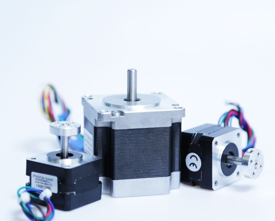
If you have ever had the pleasure of dismantling an old printer to save electronic components, you may encounter many cylindrical mysterious motors with 4 or more wires protruding from the sides. Did you hear the typical buzz of a desktop 3D printer or the buggy electromechanical symphony of disks in a CD drive? If so, then you are faced with a stepper motor!
Stepper motors make the electromechanical world rotate (with higher torque!), But unlike a conventional DC motor, controlling a stepper motor requires a little more than the current through two wires. This article will talk about the theory of design and operation of a stepper motor. As soon as we consider the basics, the author of this guide will show how to build simple circuits for controlling stepper motors, and then how to use special driver microcircuits.
Step 1: What makes a motor a stepper motor?
Who may need more than two wires and an H-bridge? What for? Well, unlike conventional DC brush motors built for maximum RPM (or kV for RC), stepper motors are brushless motors designed for high torque (subsequently lower speed) and more accurate rotational movement. While a typical DC motor is great for rotating the propeller at high speed to achieve maximum traction, a stepper motor is better for rolling a sheet of paper in sync with the inkjet mechanism inside the printer or for carefully rotating a linear rail shaft in an CNC mill.
Inside, stepper motors are more complex than a simple DC motor, with several coils around the core with permanent magnets, but with this added complexity more control is provided. Due to the careful arrangement of the coils built into the stator, the rotor of the stepper motor can rotate with a given step, changing the polarity between the coils and switching their polarity in accordance with the established ignition scheme. Stepper motors are not all made the same, and for their internal execution unique (but basic) schemes are required. We will discuss the most common types of stepper motors in the next step.
Step 2: Types of Stepper Motors
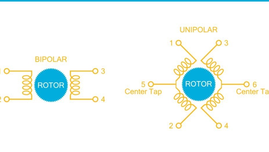
There are several different designs of stepper motors. These include unipolar, bipolar, universal and variable resistance. We will discuss the design and operation of bipolar and unipolar motors, as this is the most common type of motor.
Unipolar motor
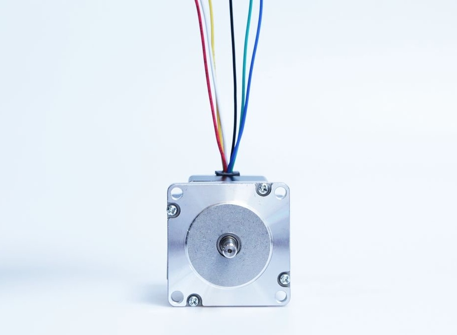
Unipolar motors usually have five, six or eight wire leads coming from the base, and one coil per phase. In the case of a five-wire motor, the fifth wire is the connected central taps of the pairs of coils. In a six-wire engine, each pair of coils has its own central tap. In an eight-wire engine, each pair of coils is completely separate from the others, which allows it to be connected in various configurations. These additional wires allow you to drive unipolar motors directly from an external controller with simple transistors to control each coil separately. An ignition circuit in which each coil is driven determines the direction of rotation of the motor shaft. Unfortunately, given that only one coil is supplied at a time, the holding torque of a unipolar motor will always be less than that of a bipolar motor of the same size. Bypassing the central taps of a unipolar motor, it can now work as a bipolar motor, but this will require a more complex control scheme. In the fourth step of this article, we will drive a unipolar motor, which should clarify some of the concepts presented above.
Bipolar motor
Bipolar motors typically have four wires and are more durable than a unipolar motor of comparative size, but since we only have one coil per phase, we need to turn the current through the coils to go one step. Our need to change the current means that we will no longer be able to control the coils directly with a single transistor, instead a complete h-bridge circuit. Building the right h-bridge is tedious (not to mention two!), So we will use a dedicated bipolar motor driver (see Step 5).
Step 3: Understanding Stepper Motor Specifications
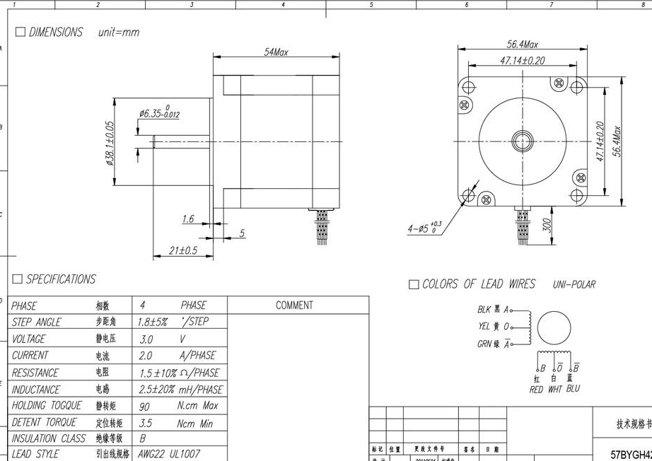
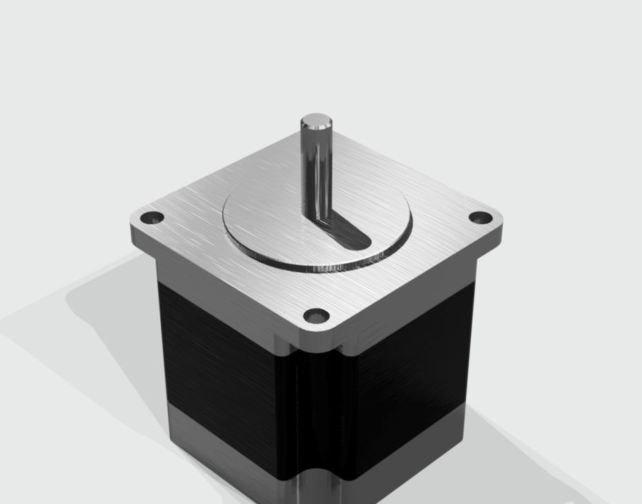
Let's talk about how to determine engine specifications. If you've come across a square engine with a specific three-piece assembly (see Figure three), it's most likely a NEMA engine. The National Association of Electrical Manufacturers has a specific standard for motor specifications that uses a simple letter code to determine the diameter of the front of the engine, type of mount, length, phase current, operating temperature, phase voltage, revolution steps and wiring.
Read engine passport
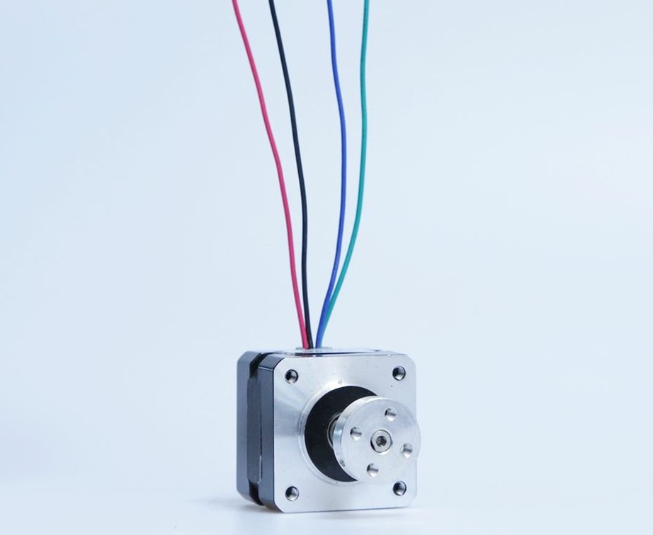
For the next step, this unipolar motor will be used. Above is a data table. And although it is concise, it provides us with everything we need for proper operation. Let's look at what's in the list:
Phase: This is a four-phase unipolar motor. The internal engine can have any number of real coils, but in this case they are grouped into four phases, which can be controlled independently.
Angle pitch: With an approximate resolution of 1.8 degrees per step, we get 200 steps per revolution. Although this is a mechanical resolution, with the help of the micro-junction we can increase this resolution without any changes to the engine (more about this in step 5).
Voltage: The rated voltage of this motor is 3 volts. This is a function of the current and the nominal resistance of the motor (Ohm's law V = IR, therefore 3V = 2A * 1.5Ω)
Current: how much current does this motor need? Two amperes per phase! This figure will be important when choosing our power transistors for the basic control circuit.
Resistance: 1.5 ohms per phase will limit what current we can supply to each phase.
Inductance: 2.5 mH. The inductive nature of the motor coils limits the charging speed of the coils.
Holding moment: this is how much actual force we can create when voltage is applied to the stepper motor.
Holding moment: this is what holding moment we can expect from the engine when it is not energized.
Insulation class: Class B is part of the NEMA standard and gives us a rating of 130 degrees Celsius. Stepper motors are not very efficient, and the constant consumption of maximum current means that they will become very hot during normal operation.
Winding indicators: wire diameter 0.644 mm., Number of turns in diameter 15.5, cross section 0.326 mm2
Coil pair detection
Although the resistance of the coil windings can vary from motor to motor, if you have a multimeter, you can measure the resistance on any two wires, if the resistance is <10 Ohms, you probably found a pair! This is basically a trial error process, but it should work for most engines unless you have a part / specification number.
Step 4: Direct control of stepper motors
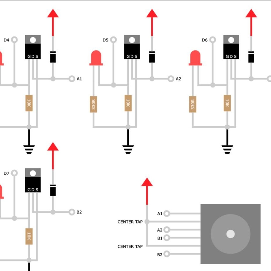
Due to the location of the wires in a unipolar motor, we can sequentially turn on the coils using only simple power MOSFETs. The figure above shows a simple circuit with a MOS transistor. This arrangement allows you to simply control the logic level using an external microcontroller. In this case, the easiest way is to use an Intel Edison motherboard with a circuit board style Arduinoto get easy access to the GPIO (however, any micro with four GPIOs will do). The IRF510 N-channel high-power MOSFET is used for this circuit. The IRF510, capable of consuming up to 5.6 amperes, will have enough free power to meet the needs of the motor at 2 amperes. LEDs are not needed, but they will give you a good visual confirmation of the sequence of work. It is important to note that the IRF510 must have a logic level of at least 5 V so that it can consume sufficient current for the motor. The engine power in this circuit will be 3 V.
Work sequence
Full control of a unipolar motor with this setting is very simple. In order to rotate the engine, we need to turn on the phases in the given mode so that it rotates correctly. To rotate the motor clockwise, we will control the phases as follows: A1, B1, A2, B2. To rotate counterclockwise, we simply change the direction of the sequence to B2, A2, B1, A1. This is good for basic control, but what if you want more accuracy and less work? Let's talk about using a dedicated driver to make things a lot easier!
Step 5: stepper motor driver boards
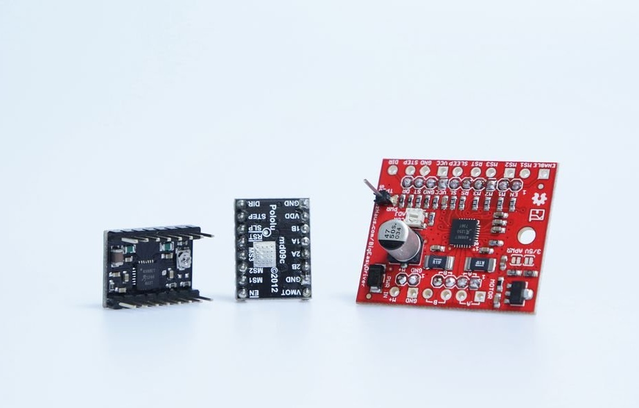
If you want to start controlling bipolar motors (or unipolar motors in a bipolar configuration), you need to take a special driver control board. The photo above shows the Big Easy Driver and the carrier board for the A4988 stepper motor driver. Both of these boards are printed circuit boards for the microstep two-pole Allegro A4988 stepper motor driver, which is by far one of the most common chips for driving small stepper motors. In addition to having the necessary dual h-bridges for controlling a bipolar motor, these boards offer many options for tiny, inexpensive packaging.
Mounting
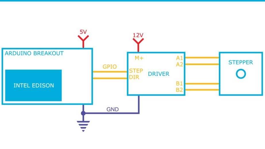
These universal boards have an amazingly low connection. You can start controlling the engine using only three connections (only two GPIOs) with your main controller: common ground, pitch and direction. The step step and its direction remain floating, so you need to bind them to the reference voltage with a load resistor. The pulse sent to the STEP pin will move the motor one step at a resolution in accordance with the microstep reference pins. The logic level at the DIR pin determines whether the motor will rotate clockwise or counterclockwise.
Microstep engine
Depending on how the pins M1, M2 and M3 are installed, you can achieve increased motor resolution by microsteping. The microstep includes sending a variety of pulses to pull the motor between the electromagnetic resolution of the physical magnets in the rotor, providing very precise control. The A4988 can go from a full step to a sixteenth step resolution. With our 1.8 degree engine, this will provide up to 3200 steps per revolution. Talk about the little details!
Codes / Libraries
Connecting motors can be easy, but what about controlling them? Check out these ready-made code libraries for stepper motor control:
Stepper - The classic built into the Arduino IDE allows you to perform a basic step and control the speed of rotation.
Accel stepper - A much more full-featured library that allows you to better control multiple engines and provides the correct acceleration and deceleration of the engine.
Intel C ++ MRAA Stepper - A lower-level library for those who want to delve into the management of the raw C ++ stepper motor using Intel Edison.
This knowledge should be enough for you to understand how to work with stepper motors in the electromechanical world, but this is only the beginning.
