» Electronics » Power supplies »Power supply of an old printer, how to convert it into an adjustable power source

The power supply of an old printer, how to convert it into an adjustable power source


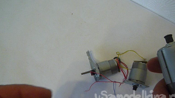
Many people throw a printer out of the garbage without thinking twice. But if you disassemble the old faulty printer, you can get a lot of the necessary parts for homemade. You can get high-quality metal shafts, rods, guides, stepper motors from the printer that you can use to create home-made CNCs and similar home-made products. The printer has USB connectors, a variety of position sensors. We use collector electric motors to create electric drills and to drive a variety of models and toys and so on.
The power supply of an old printer, how to convert it into an adjustable power source


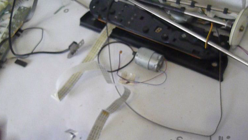
In general, we give a second life to the old office equipment.
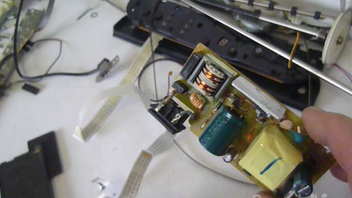
Now we will consider the topic of remaking the switching power supply from a Canon printer and its further application in everyday life. Printers are installed transformerless power supplies built on a pulsed circuit. They can produce voltages from 24 to 42 volts with a load current of up to 2 amperes. These power supplies are quite reliable, have a large resource and can work for a long time.

Enumeration of tools and materials.
- switching power supply from a Canon-1pc printer;
- tuning multiturn resistor for 5-10Kom -1pcs;
-connecting wires;
soldering iron;
-tester;
-1 minvoltmeter;
- glue;
- a piece of aluminum sheet;
- cap from the tube;
-plastic tube from the core of the fountain pen -1pcs.

Step one. Alteration of the circuit of the pulse power supply of the printer.

Consider the circuit of this switching power supply.

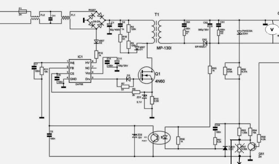
When the power supply is turned on at the SB terminal, we have a voltage of 7 V, and there is no voltage at the +24 terminal. If you need an unregulated voltage of 24 V, then you can connect the outputs SB and +24 to each other.

Our task is to regulate the controlled zener diode TL431. In the diagram, it is indicated as IC51. The controlled zener diode TL431 stabilizes the voltage at the output of the power supply depending on the load as it is included in the feedback circuit.We solder the resistor R57 on the board.

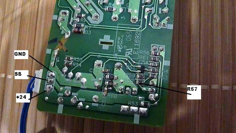
Instead, we connect a tuning multi-turn resistor with a nominal value of 5 to 10K.

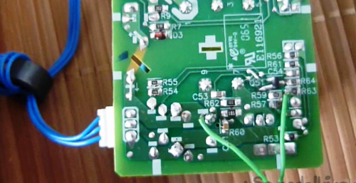
Now the desired voltage can be set by rotating the axis of the tuning resistor. A multi-turn trimmer gives a smoother adjustment of the output voltage of the power supply.

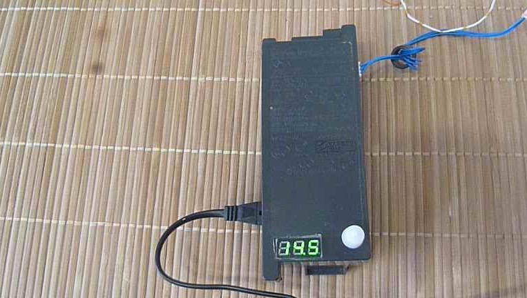
We connect a minivoltmeter to the output of the converted power supply (in principle, any voltmeter can be connected, but there is simply not enough space in the standard case). I put an additional radiator from an aluminum strip on the diode assembly in order to reduce heating at maximum load currents. You can also drill in the vent holes.

We install the board in the native standard building (if desired, you can place it in a more spacious case, add output terminals). In the top cover we make a window for a voltmeter and an opening for a tuning resistor. The trimmer itself is glued with hot glue. On a rotary axis of the resistor we put a piece from the plastic rod (pre-smear with glue). Glue the cap from the tube onto the rod.

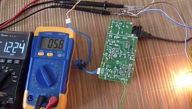
Step Two Checking the operation of the power supply.

After the alteration, I received the limits of the power supply regulation from 4.5 to 25 V. I connected the car lamp as a load. At a voltage of 5.8V, the current was 1.22A. At a voltage of 9.3 V, the current was 1.56 A. At a voltage of 24 V, the current was 2.2 A. It is an acceptable result.


As a result of a small alteration, they received a free compact adjustable power source. It can be used as a charger for smartphones, screwdrivers. Also power LED strips, homemade products - it all depends on your needs.
More alteration and pulse test from the printer can be seen in the video

I wish you all good health and good luck in your life and work!
9.1
8.2
8.1

Add a comment

    • smilesmilesxaxaokdontknowyahoonea
      bossscratchfoolyesyes-yesaggressivesecret
      sorrydancedance2dance3pardonhelpdrinks
      stopfriendsgoodgoodgoodwhistleswoontongue
      smokeclappingcraydeclarederisivedon-t_mentiondownload
      heatirefullaugh1mdameetingmoskingnegative
      not_ipopcornpunishreadscarescaressearch
      tauntthank_youthisto_clueumnikacuteagree
      badbeeeblack_eyeblum3blushboastboredom
      censoredpleasantrysecret2threatenvictoryyusun_bespectacled
      shokrespektlolprevedwelcomekrutoyya_za
      ya_dobryihelperne_huliganne_othodifludbanclose
15 comments
Quote: PapaBOSS
I'll try!

"Do not fit, kill, mudila!" -
Well, of course, I got in ... Killed.
Following rummage climbs
With a cry: “He won’t kill everyone!”
Whatever they say -
Indomitable people.

The scheme is wrong, not ... there aren’t enough words, especially since the author scattered it on the Internet, for example- "Adjustable power supply from a Canon printer power supply
April 5, 2019 votak131 15,696 views, "Useful DIY" website,

In fact, these schemes look something like this,


Papaboss
I'll try!
At a voltage of 5.8V, the current was 1.22A. At a voltage of 9.3 V, the current was 1.56 A.
I strongly doubt that under such modes the PSU will work for a long time, and if it works, it is unlikely to be stable. I allow normal adjustment and operation from 20 V to 25 V, but the parameters indicated by the author are already too much
Yes, now in most household appliances switching power supply line converters. So, they can not be used again after the failure of the technology itself?
Guest Vita
When it comes to PSUs with pulse converters, galvanic isolation is provided by a small transformer included in the breaker load. If it pierces, there is little pleasure. Pass-through capacitors are placed in the filters, also a potential injection.
Moment
In this way, I reworked the pulse adapters to 7.5 V 12 V 5V by changing the voltage to control 431. According to the current protection, the resistor works in the source of the key, the circuit is really protected from overloads
Moment
In the diagram, a complete bullshit 431 is turned on so that both outputs are on the minus LED opto pair can not be controlled by control terminal 431 on the signet there is no galvanic connection in and out, you can solder a variable resistor instead of a transistor since tr.must really change U on control 431
Quote: Guest Vita
use such a device for power, when setting up the equipment, is doubtful about TB.

Why? If you do not take into account the crazy scheme drawn, then the jambs in the absence of current control and in the use of a building resistor instead of an alternating current should not affect the OT. In fact, the source of the printer is designed and manufactured correctly.
Guest Vita
I don’t like the author’s entry, throwing it away, just do not need anything, but use it for its intended purpose as a ready-made power supply, taking into account voltage and current (DRILLS, SCREWDRIVERS, CHARGING). Once again, I repeat that using such a device for power, when setting up the equipment, causes doubt about TB.
Quote: popvovka
Perhaps there is still a capacitor between the high-voltage and low-voltage parts.

A slice of the noise suppressing Y-capacitor is visible in the slot. But it is not on the diagram. ((
Clear business not for. And the scheme of this block is really wrong on the Internet. The search engine finely finds it, damn the artists))
On the board, of course, there is. The optocoupler is also on the circuit, only the circuit is full of lies. And the capacitor is not used for galvanic isolation.
The interchange is clearly visible on the board. The optocoupler is visible. Perhaps there is still a capacitor between the high-voltage and low-voltage parts.
And the TL431 connection with the harness is also kind of ridiculous. If the author corrects the jambs of the scheme, it will be possible to talk about something. In the meantime - a deuce. ((
Although the very idea of ​​using components of faulty office equipment is correct, I support it.
There is some nonsense on the circuit: there is no galvanic isolation of the low voltage network. The free end of the voltage regulation resistor must be connected to the engine.

We advise you to read:

Hand it for the smartphone ...