
Greetings the inhabitants of our site!
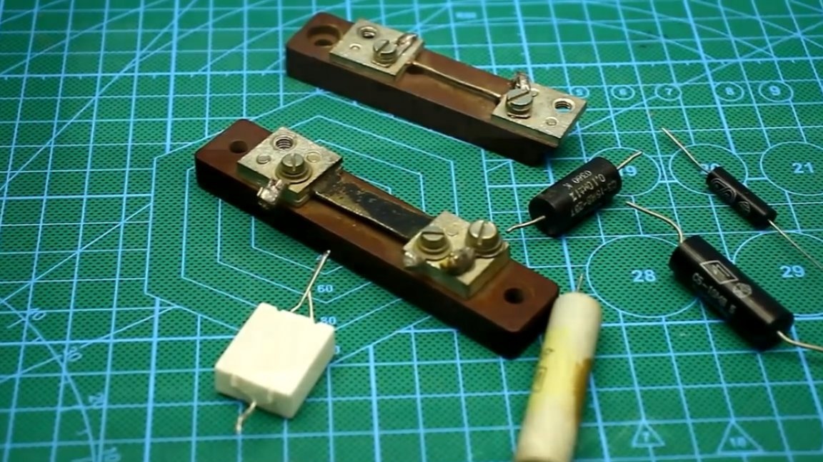
Most radio amateurs when working with power sources, very often there is a need to measure the resistance of current shunts, both home-made and industrial. And as you know with an ordinary multimeter, even a good and quite expensive one cannot measure resistance less than 0.1 Ohm.
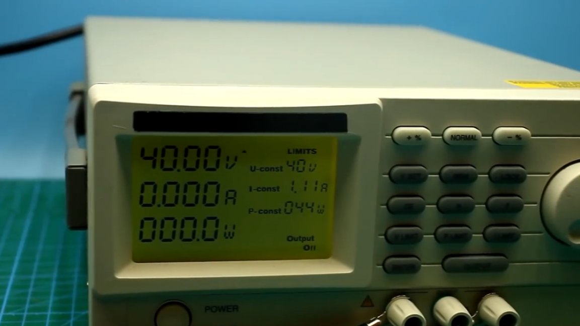
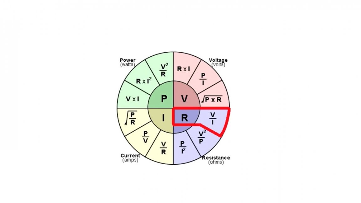
It is possible to measure the resistance of any resistor using a laboratory power supply, which has the function of limiting the current, a multimeter, and, I think, the well-known grandfather Ohm, or rather his law.

But you must admit, it would not be bad to have a specialized device that, without additional body movements, is able to measure the resistance of several resistors and current shunts. Therefore, AKA KASYAN, the author of the YouTube channel of the same name, decided to make such a device.
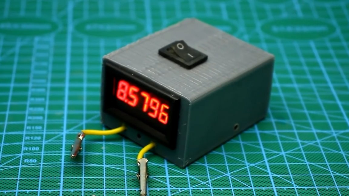
The device itself turned out to be quite compact, has fairly high accuracy and most importantly does not depend on networks, as it has its own power supply in the face of a 6F22 battery (Krona) with a voltage of 9V.
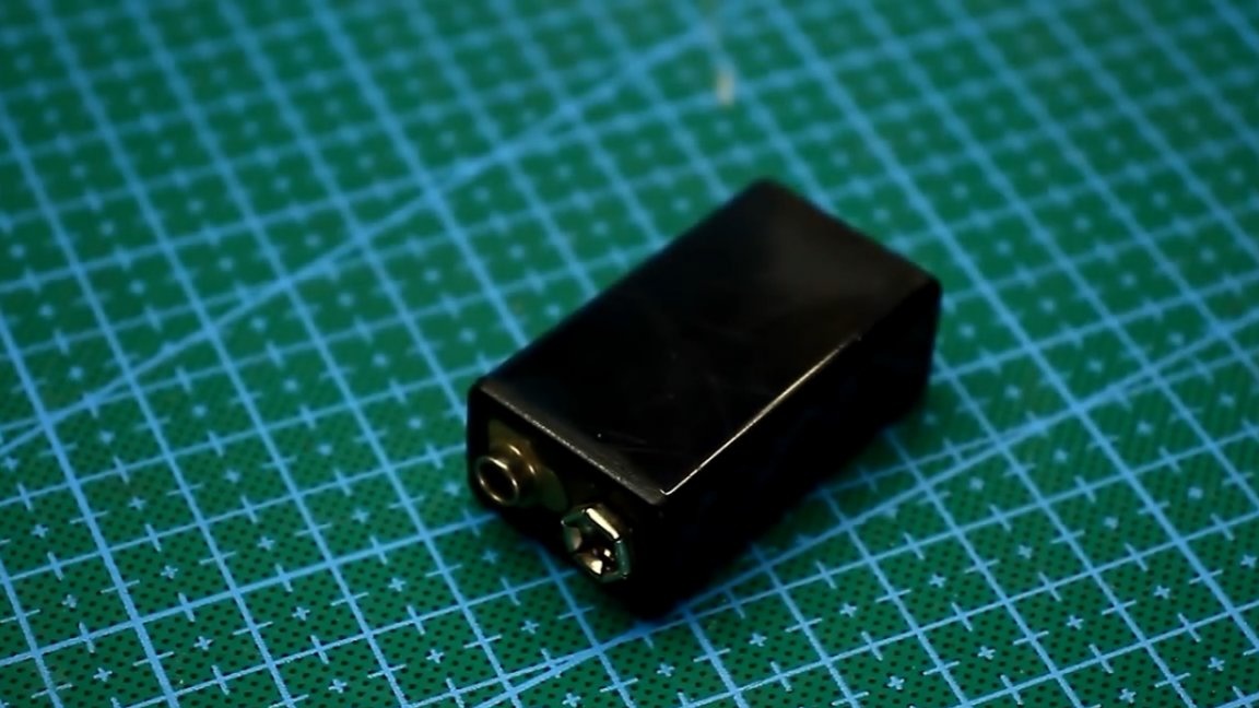
This battery is enough for quite a long time. The basis of the device is Ohm's law.
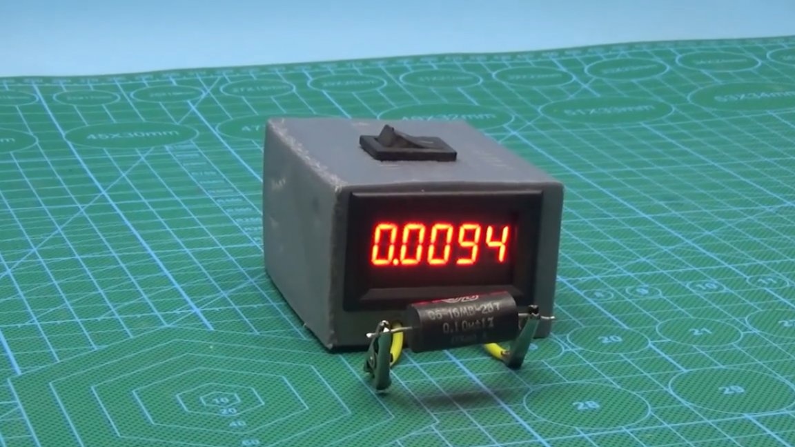
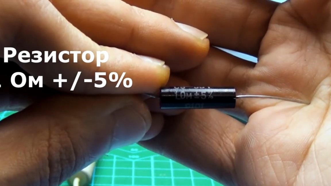
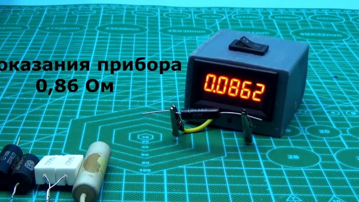
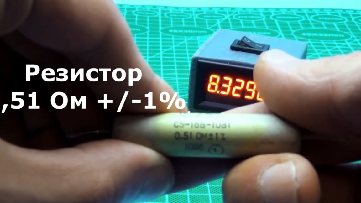
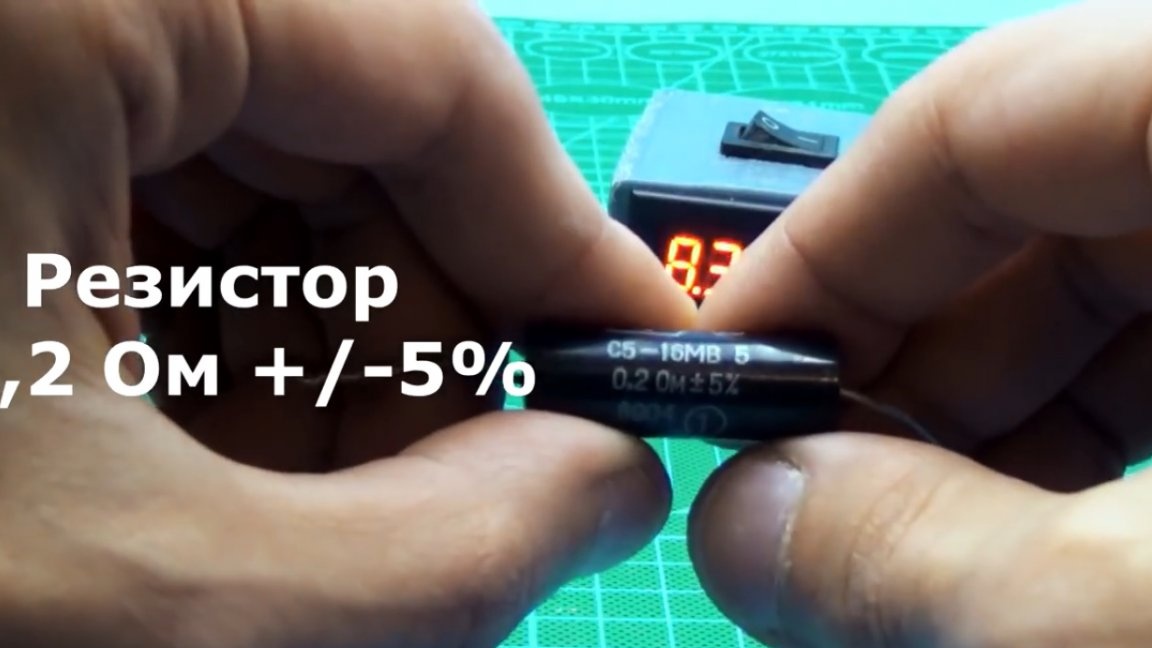
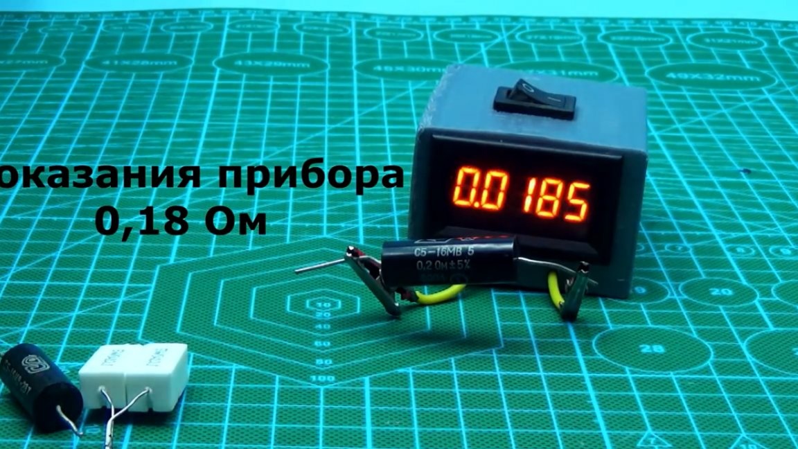
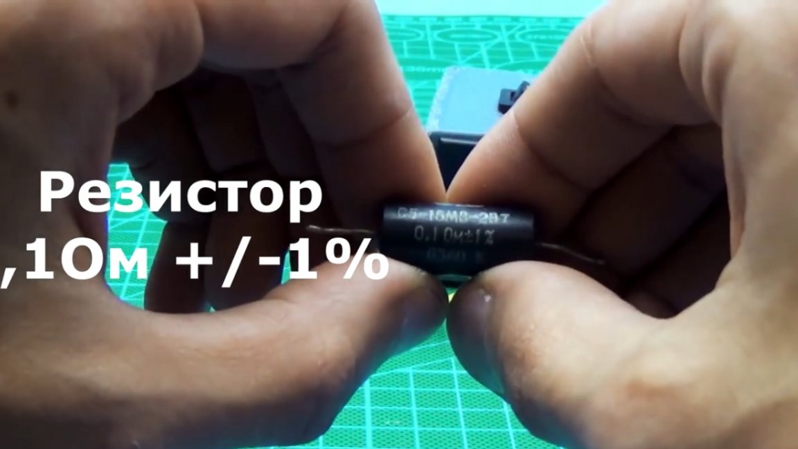
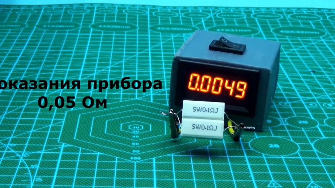
As a test, we take a resistor with an unknown resistance, which needs to be measured.
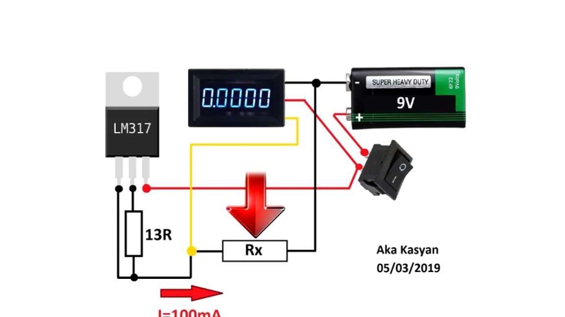
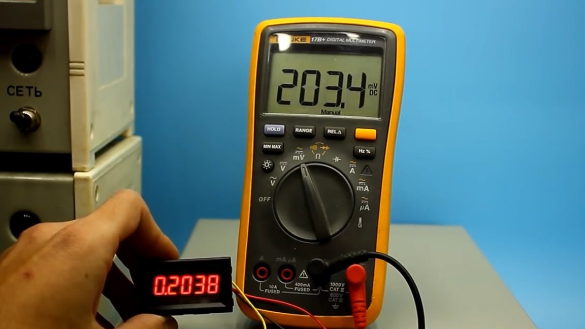
This device has a current stabilization system at 100 mA and a measuring voltmeter that measures the voltage drop across the experimental resistor. And knowing the voltage drop and the current flowing in the circuit, it will not be difficult to understand what resistance our tested resistor has.
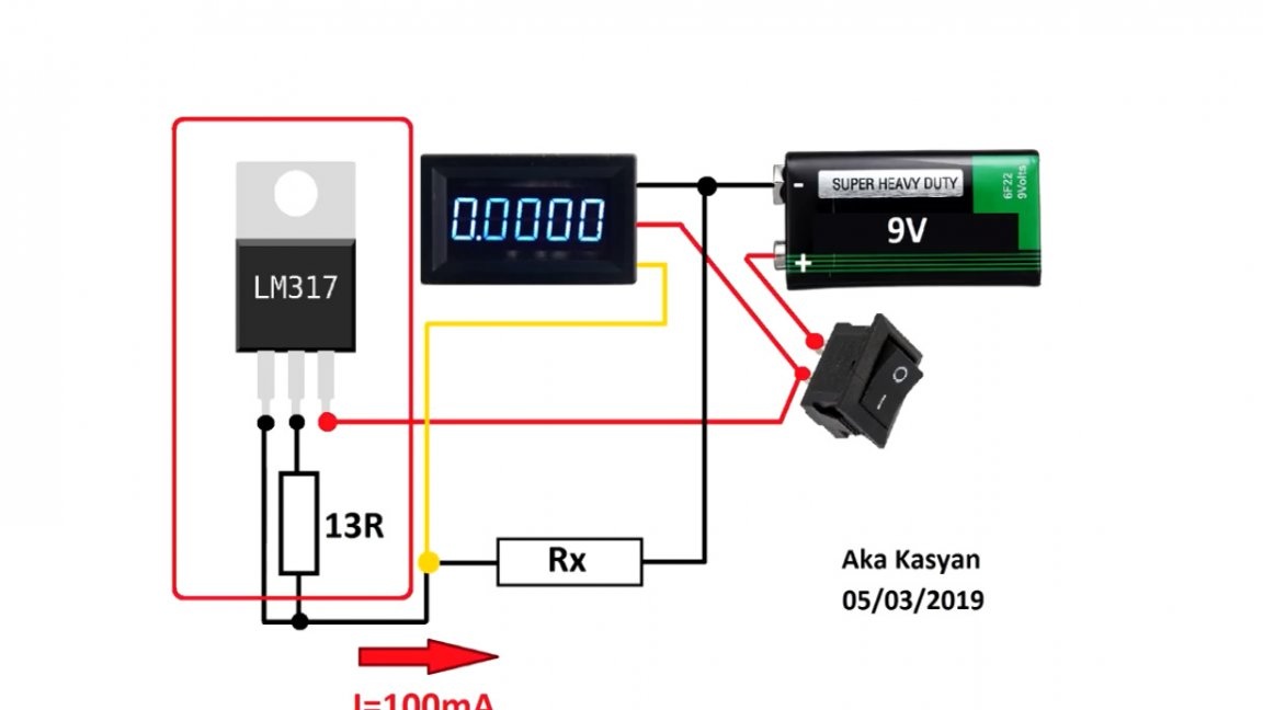
Specifically, in this example, there is no need to perform any additional calculations, since a current of 100 mA (or 0.1 A) is selected, therefore, 100 mV (or 0.1 V) on a voltmeter will mean that the resistance of the tested resistor is 1 Ohm. At readings of 10 mV, the resistance value is 0.1 Ohm, and 1 mV is the resistance, respectively, 0.01 Ohm. As you see, everything is simple, you can get used to it quickly enough.
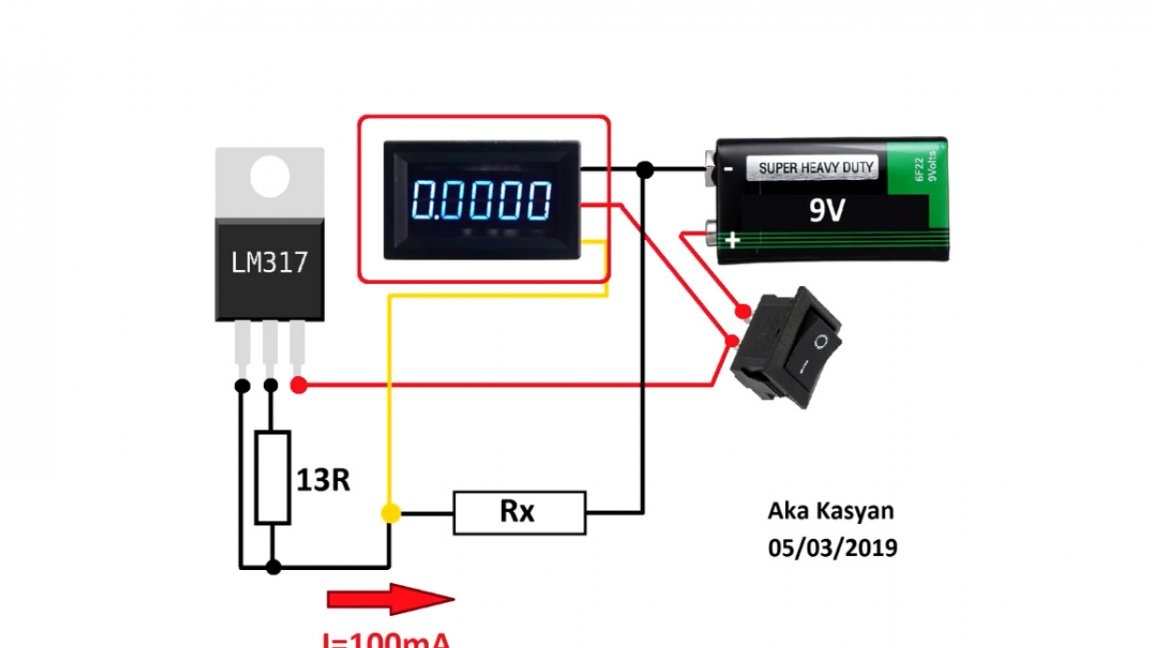
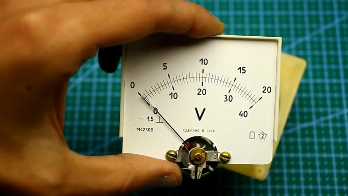
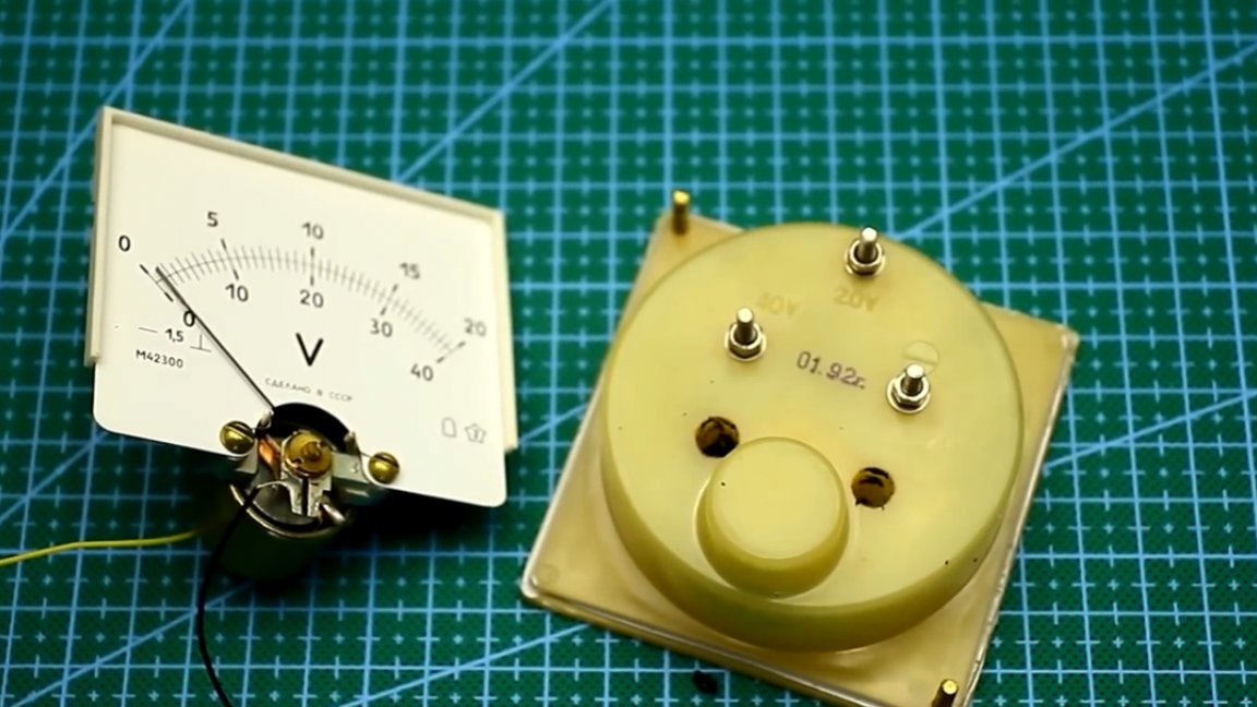
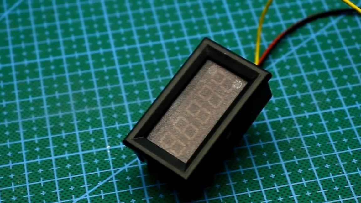
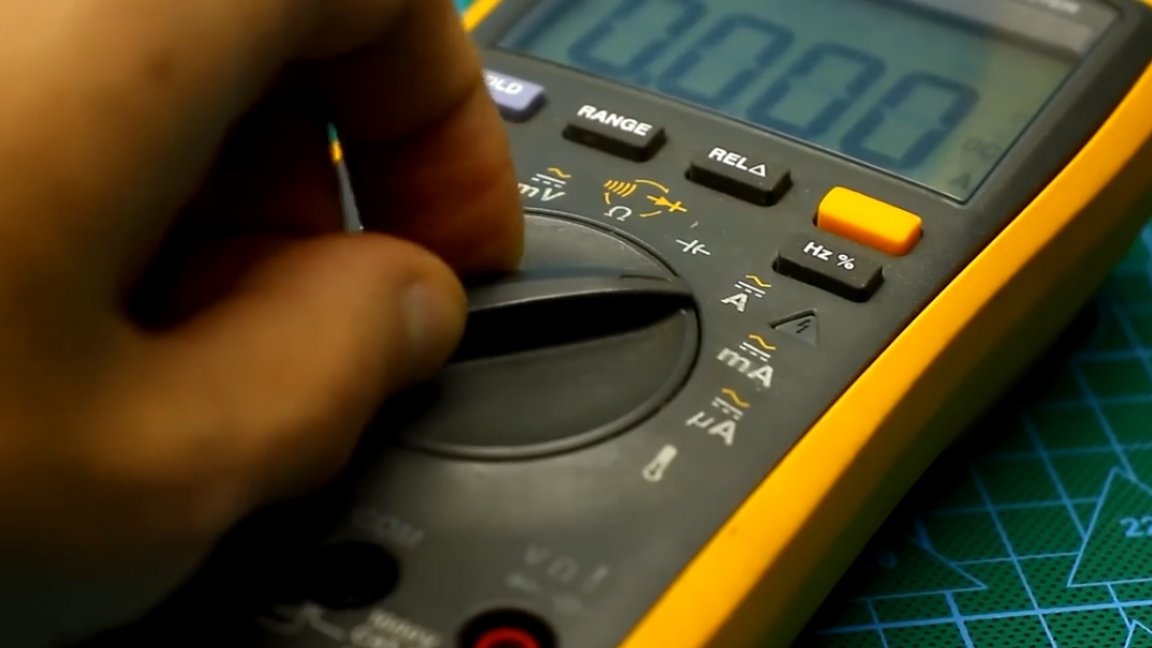
For the accurate operation of our home-made device, we need a voltmeter that can correctly measure very low voltages.Initially, the author planned to make the device analog, but the measuring heads that were tested, alas, could not display such low voltages, and the amplifier needed to be installed, which I did not want to do, since a precision digital voltmeter was available, its author purchased in the well-known Chinese trading platform Aliexpress.
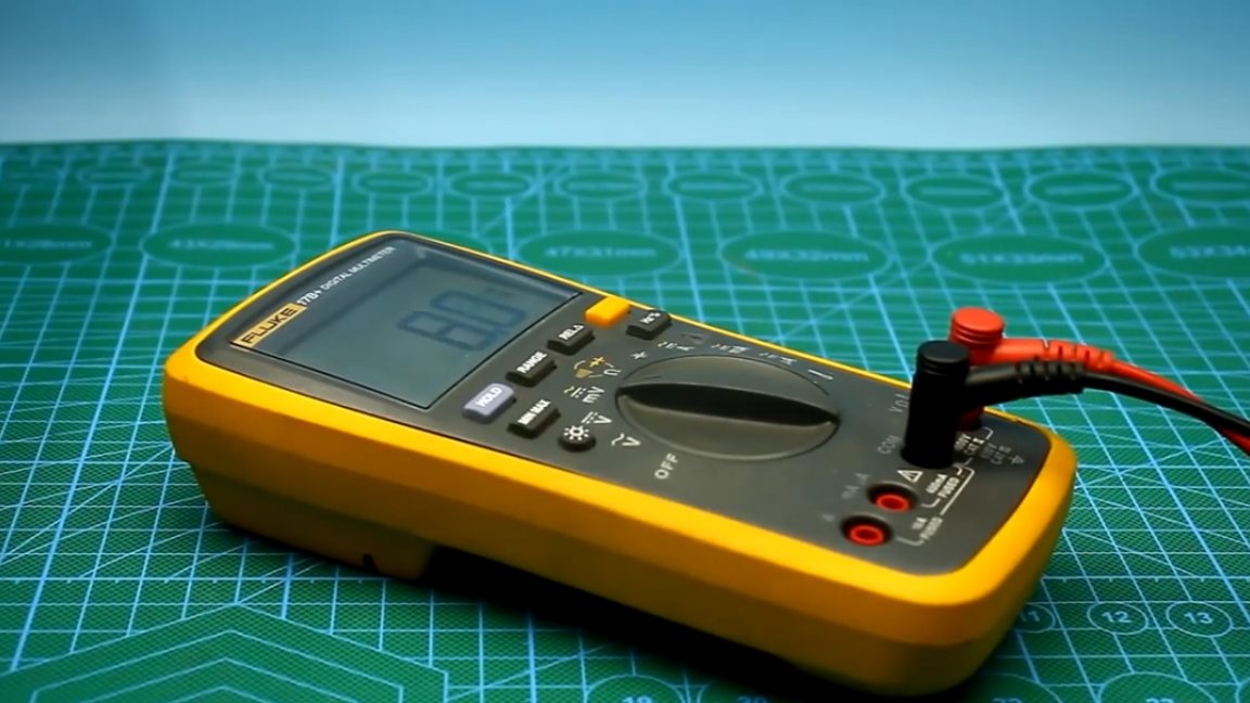
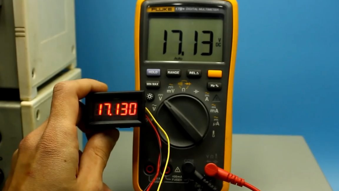
This instance, according to the seller, has a rather small error, which is only 0.3 percent. But we will not trust the seller and will perform additional calibration in the range up to 100 mV. The accuracy of the reference multimeter is 1%.
To calibrate the voltmeter, a tiny tuning resistor is provided on its board.
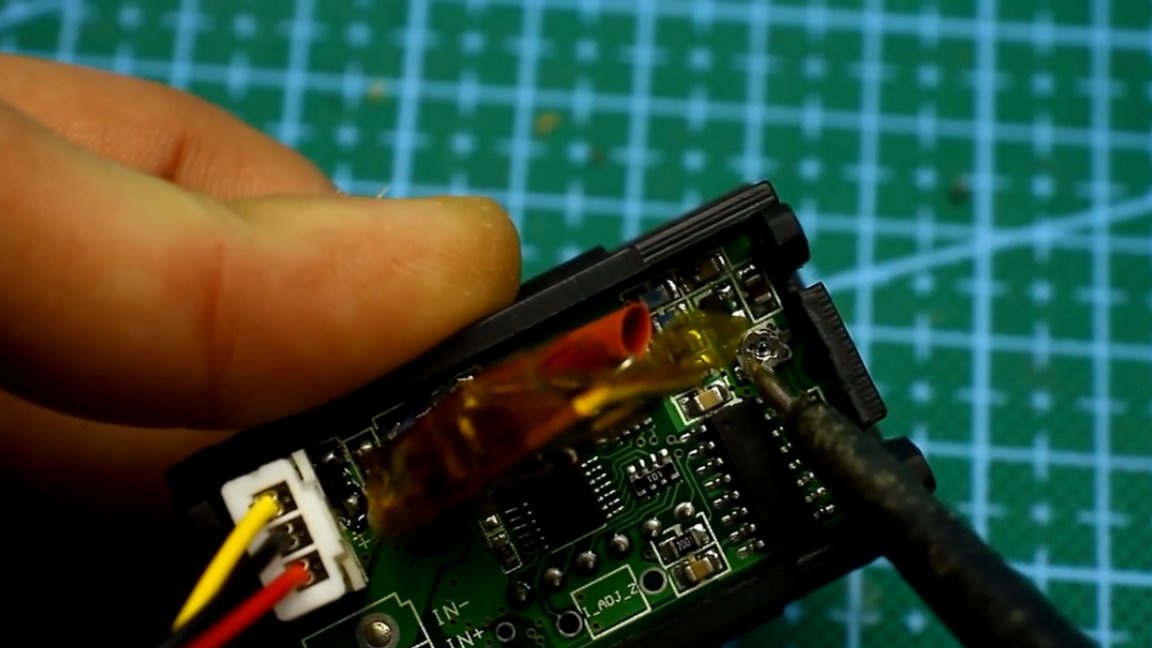
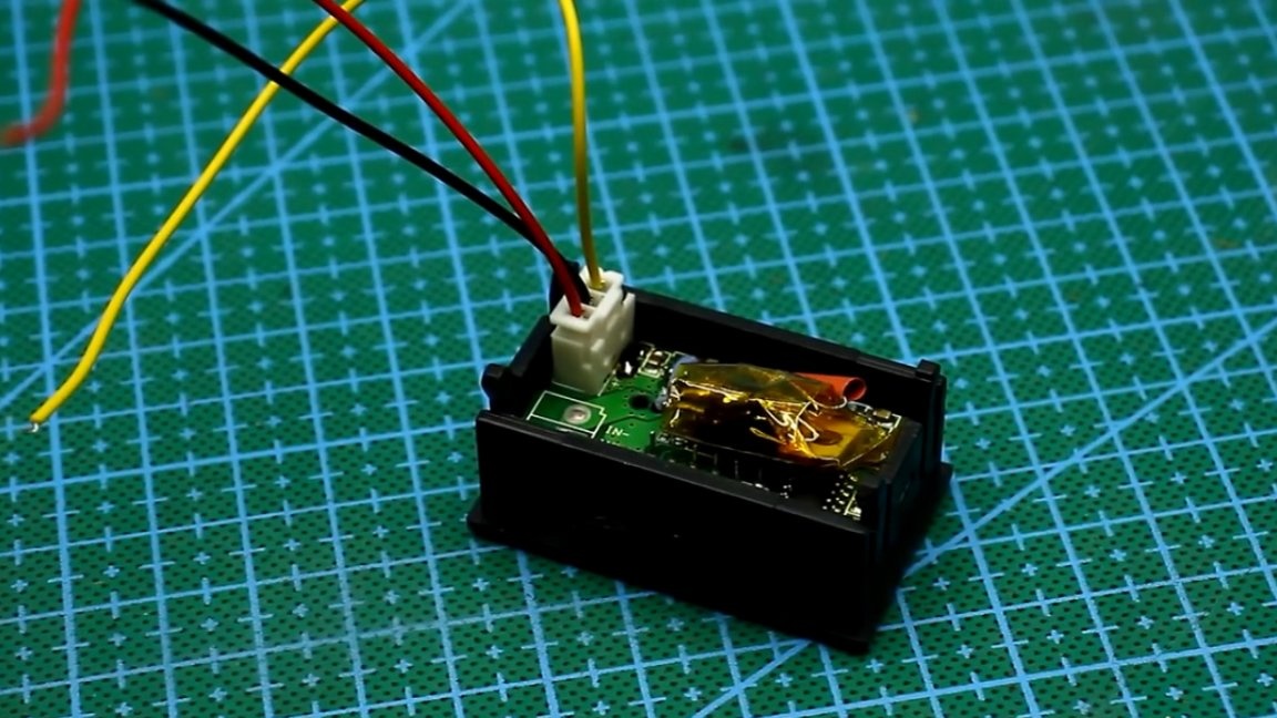
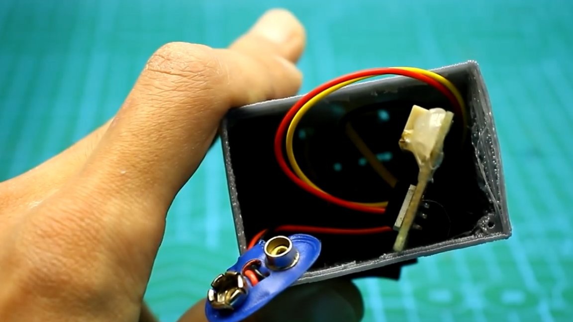
The voltmeter itself has 3 wires. Black is the mass, yellow is the measurement plus, the red wire is the plus voltage of the voltmeter.
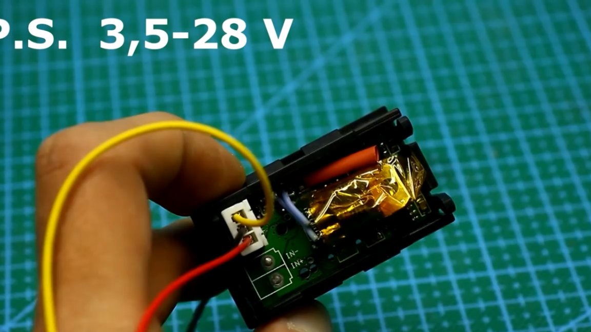
Such a voltmeter can be powered from any DC source with voltage from 3.5V to 28V.
This voltmeter is five-digit and theoretically capable of measuring voltage starting at 100 μV. But the last digits on the display should not be taken seriously, except perhaps for rounding off the values.
The minimum voltage that a voltmeter can display more or less correctly starts from 1 mV. From this it follows that the minimum resistance that our device can measure is 0.01 Ohm, or 10 mOhm.
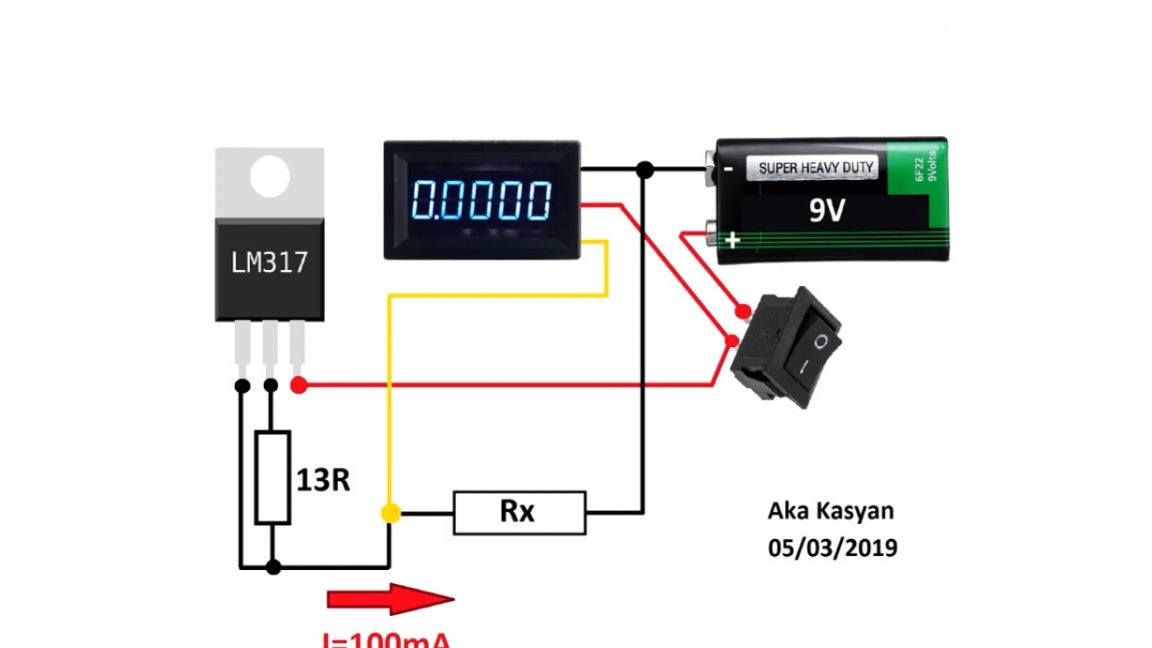
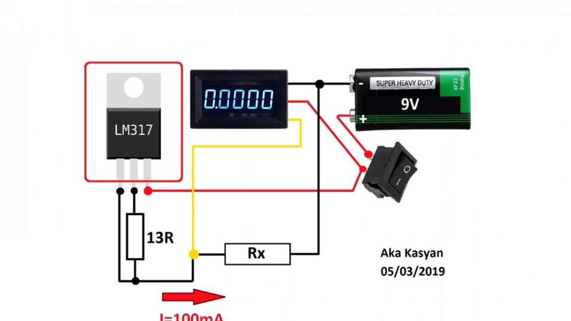
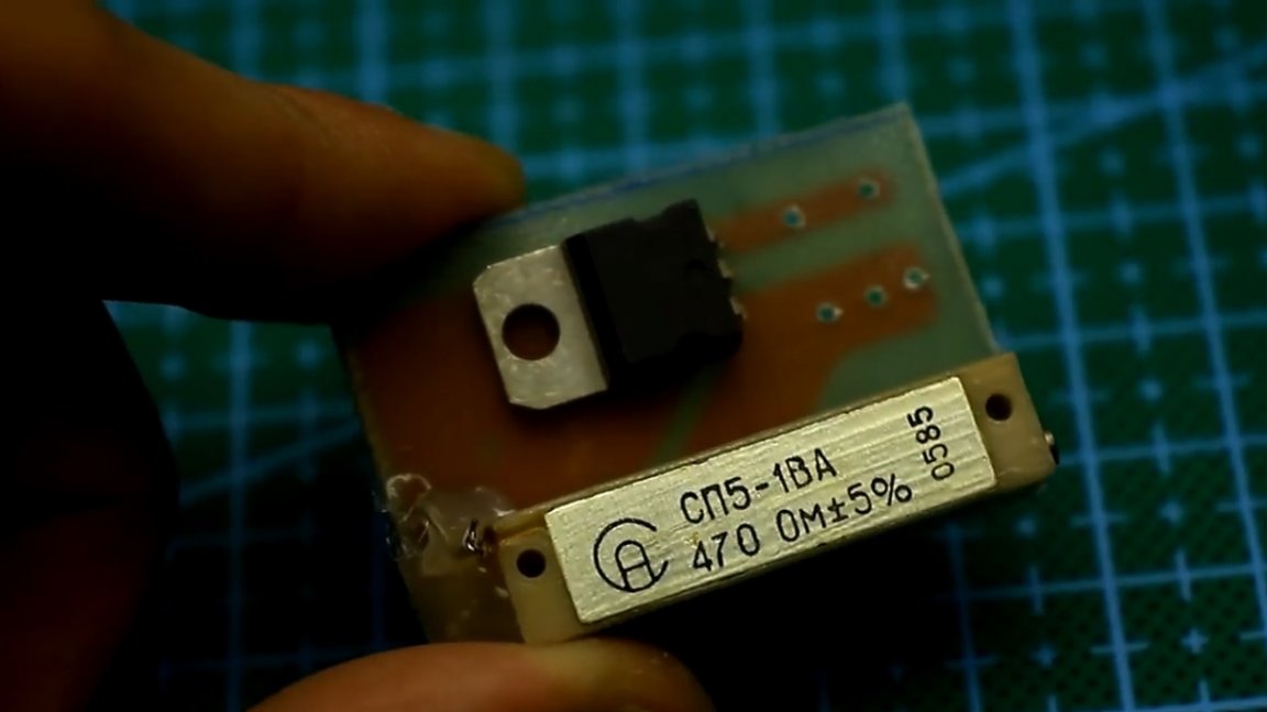
The current stabilizer consists of only two components, namely a current-setting resistor and an lm317 microcircuit, which in turn is connected using a current stabilizer circuit.
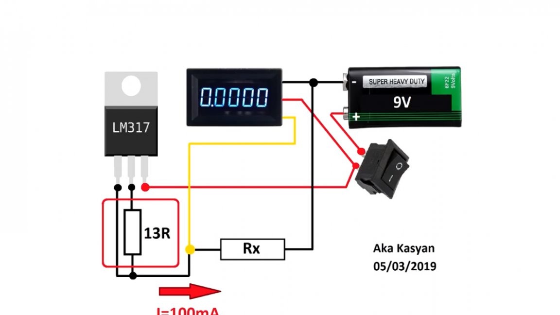
For a current of 100 mA, a resistor with a resistance of about 13 ohms is needed. In this example, the author used a tuning multi-turn resistor SP5-1 originally from a distant USSR.
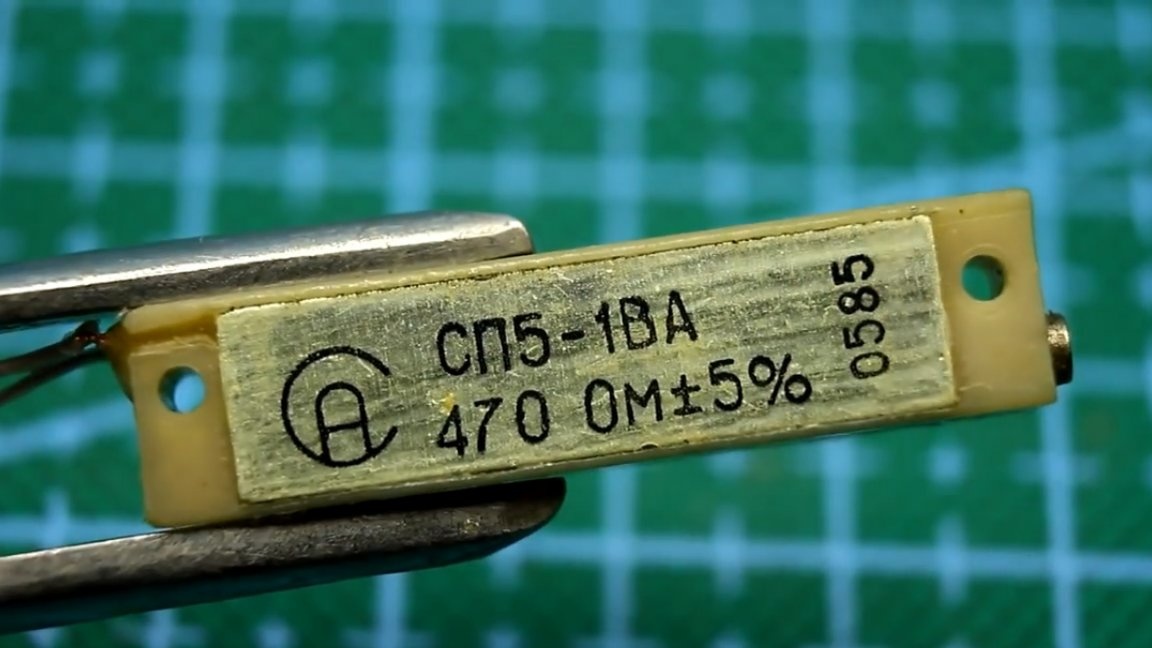
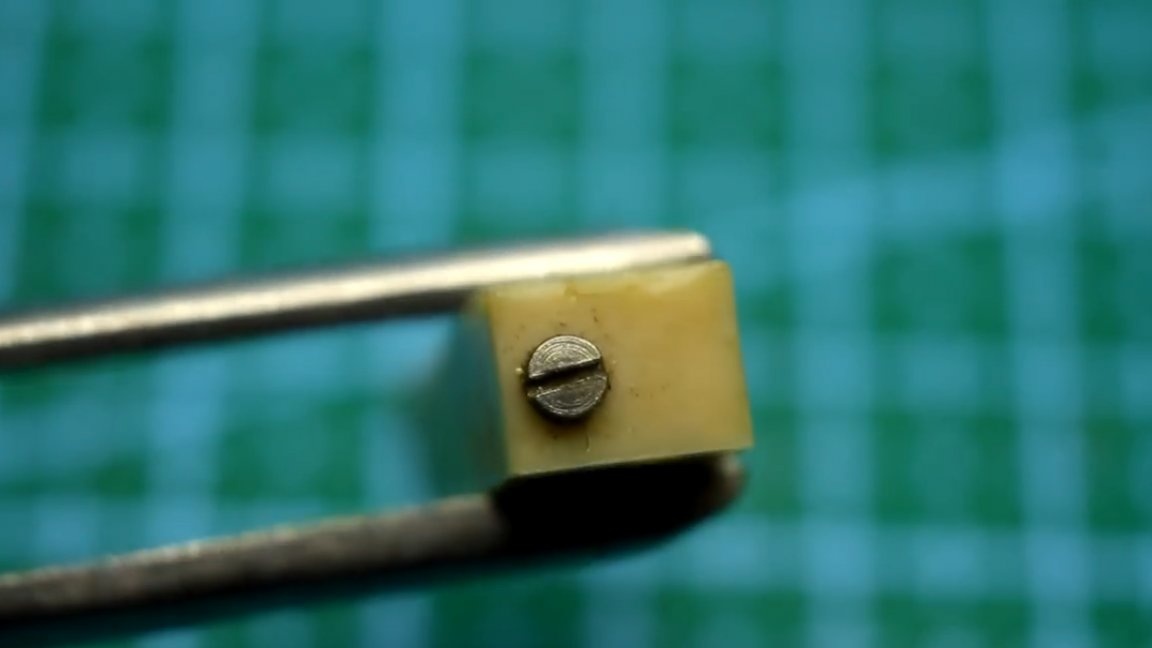
This resistor is 60 revolutions, so you can set the required resistance with fairly high accuracy.
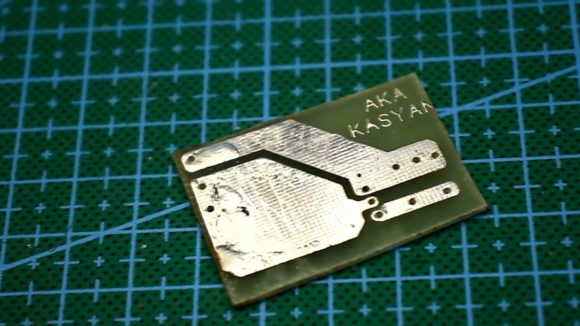
The whole circuit is made on a rather compact printed circuit board. Although here you can easily do without a board at all due to the minimum number of components.
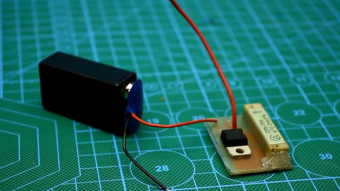
The device is assembled, now it is necessary to calibrate the circuit. To do this, we need a reference current meter. In this case, we will use the same multimeter in the ammeter mode, the error of the device in this mode is about 1 percent.
We connect everything according to the scheme.

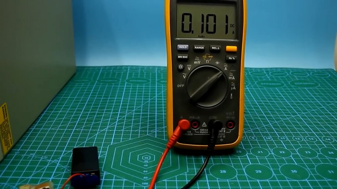
Power supply - 6F22 battery, turn the slider of the tuning resistor until we see a current value of 100 mA on the device screen.
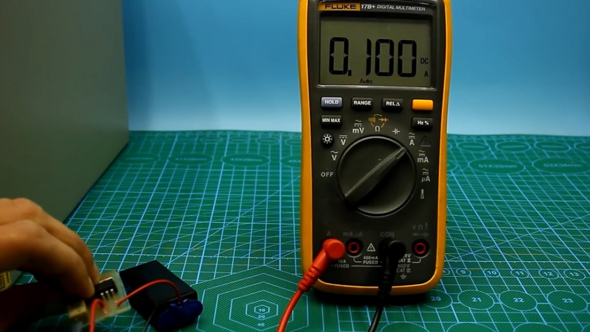
This completes all setup, it remains only to fix the screw trimmer resistor.
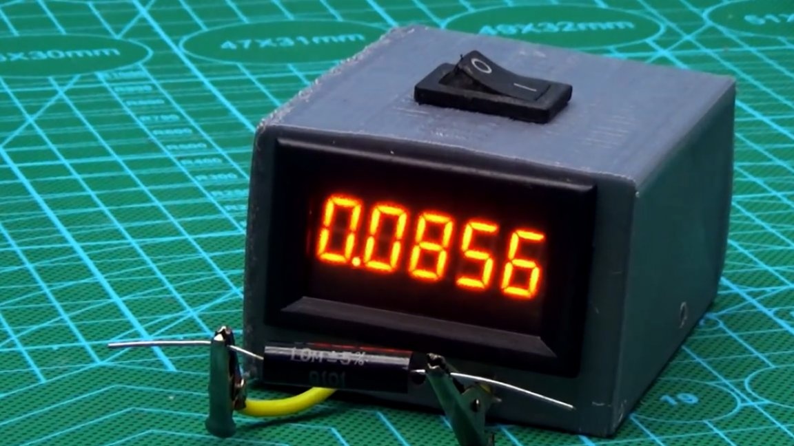
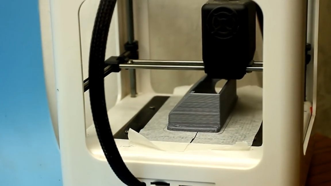
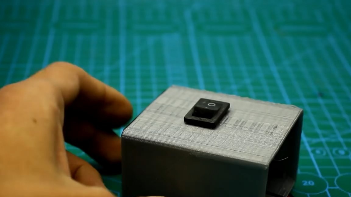
The author decided to print the case for this homemade product on a 3d printer. As you can see, it turned out not very neatly, okay.
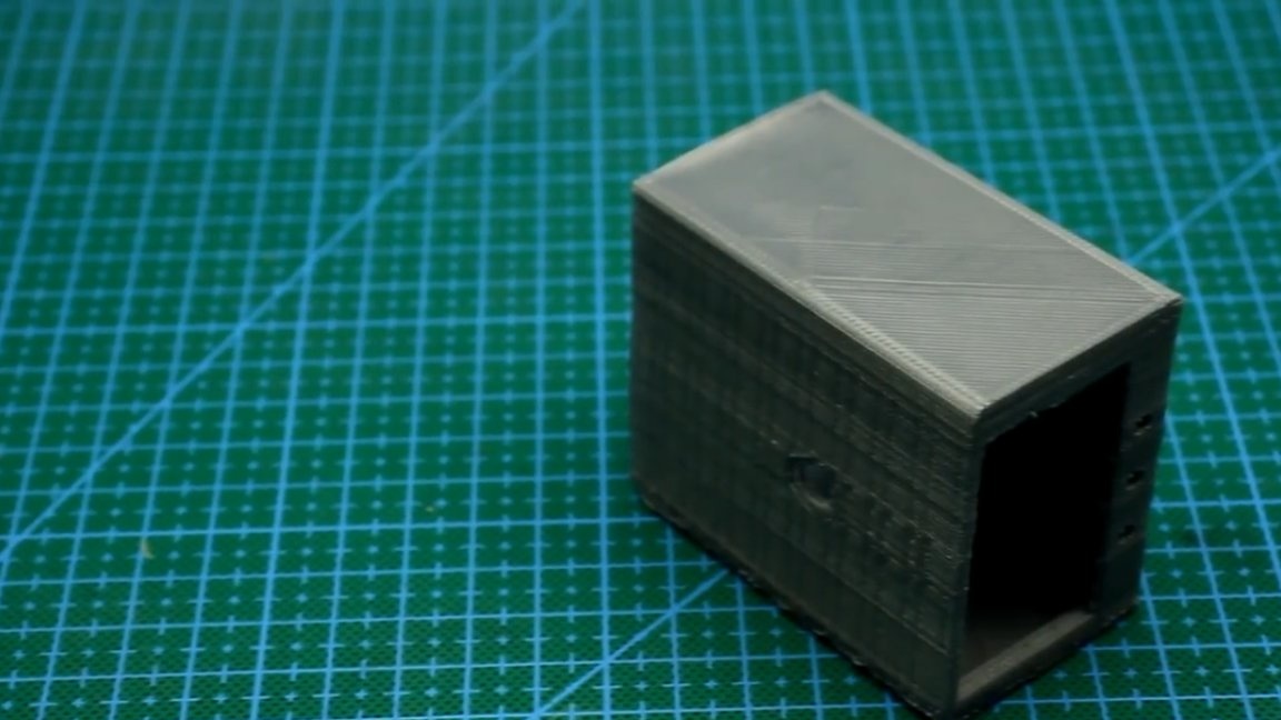
Now you can install everything in the case in its place.
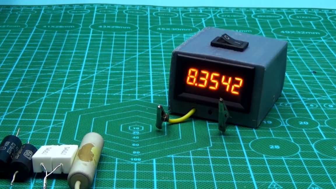
Well, now we go directly to the testing of our device in practice.
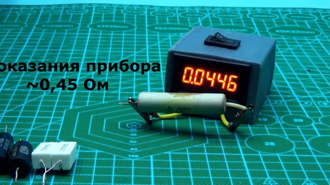
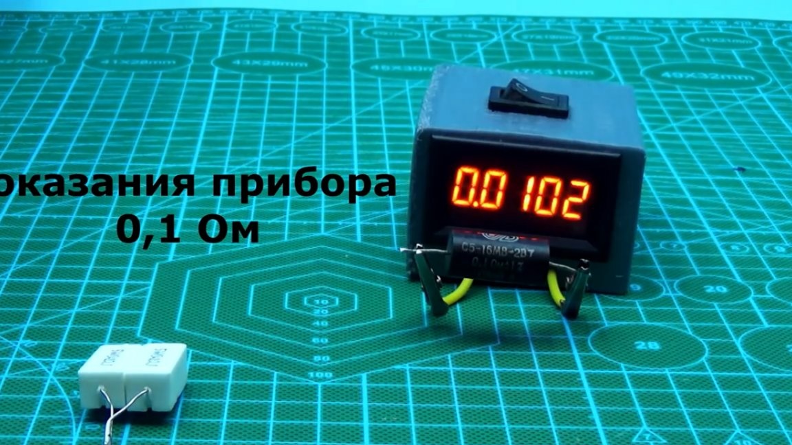
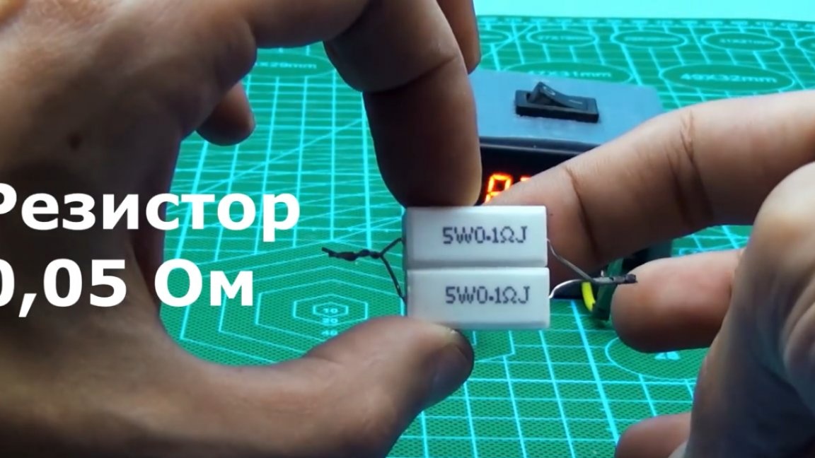
Agree, not bad, really. As a result, we have a compact and also portable milliometer.
Instrument accuracy. The error of the voltmeter readings is 1%, we add to this another 1% of the error of the current limiting system, well, add about a percent for any losses in the wires and connections. Ideally, we get an error not exceeding 3%. But when measuring resistance less than 0.01 Ohm and above 0.5 Ohm, the error increases since we calibrated the device to this range, but this, you see, is not bad, given that the assembly cost does not exceed $ 5-6.
Well, this is perhaps the time to end. Thank you for attention. See you soon!
Author's video: