Each radio amateur or electronics engineer in his laboratory has many different instruments and devices. One of the main ones is, of course, a capacitor meter, with which you can easily check its internal resistance or capacitance. Nowadays, switching power supplies are almost always used everywhere, where the ESR parameter of capacitors is an important parameter, the quality and reliability of the entire device depend on this.
Over time, the ESR in the capacitors increases, which is not good, a capacitor with increased internal resistance on the board of a switching power supply leads to increased ripple of the output voltage and its rapid failure, the capacitor starts to heat up very much, the body is deformed, it can even explode .
When repairing equipment or assembling any device, such a capacitor cannot be checked with an ordinary ohmmeter, here you will need a special device that can measure the internal resistance of the capacitor, such a device costs money.
I suggest you assemble such a device yourself, very convenient and accurate. You will find everything you need to assemble this device at the link at the end of the article.
The advantage of such a device is that the heart of this device is the attny2313 microcontroller in a local radio store, such a microcontroller in a deep package does not cost about 80 rubles. For visual control of the readings in the diagram, an LCD 0802 is provided, which has two lines of 8 characters each, you can use the other, for example, 1602 only half of the display will not be used, I used 0802, such LCD displays can be found in China, they are there pennies.
Perhaps this is the most expensive thing in the scheme. Everything else, resistors, transistors, diodes can also be bought ready-made on the same Ali Express or torn for example from other unnecessary boards.
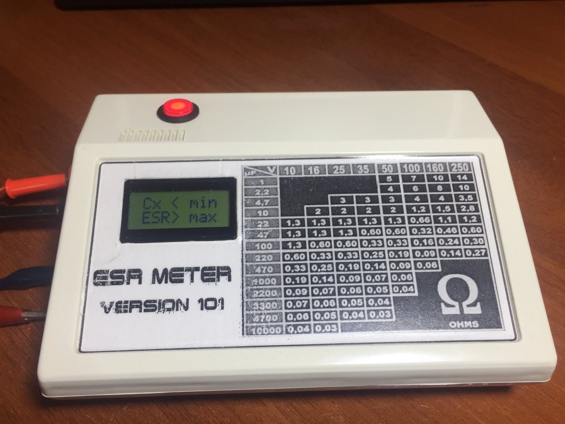
After assembling the device, you need to adjust the contrast of the display, for this we turn the tuning resistor R19, we turn until the information appears on the screen. If there is nothing on the screen, then check that the installation is correct for errors, the condition of the parts, and the controller firmware is correct.If everything worked well, then click on the button that is located on the device’s board on top of the controller, while changes to the firmware are made to the speed of response of the device.
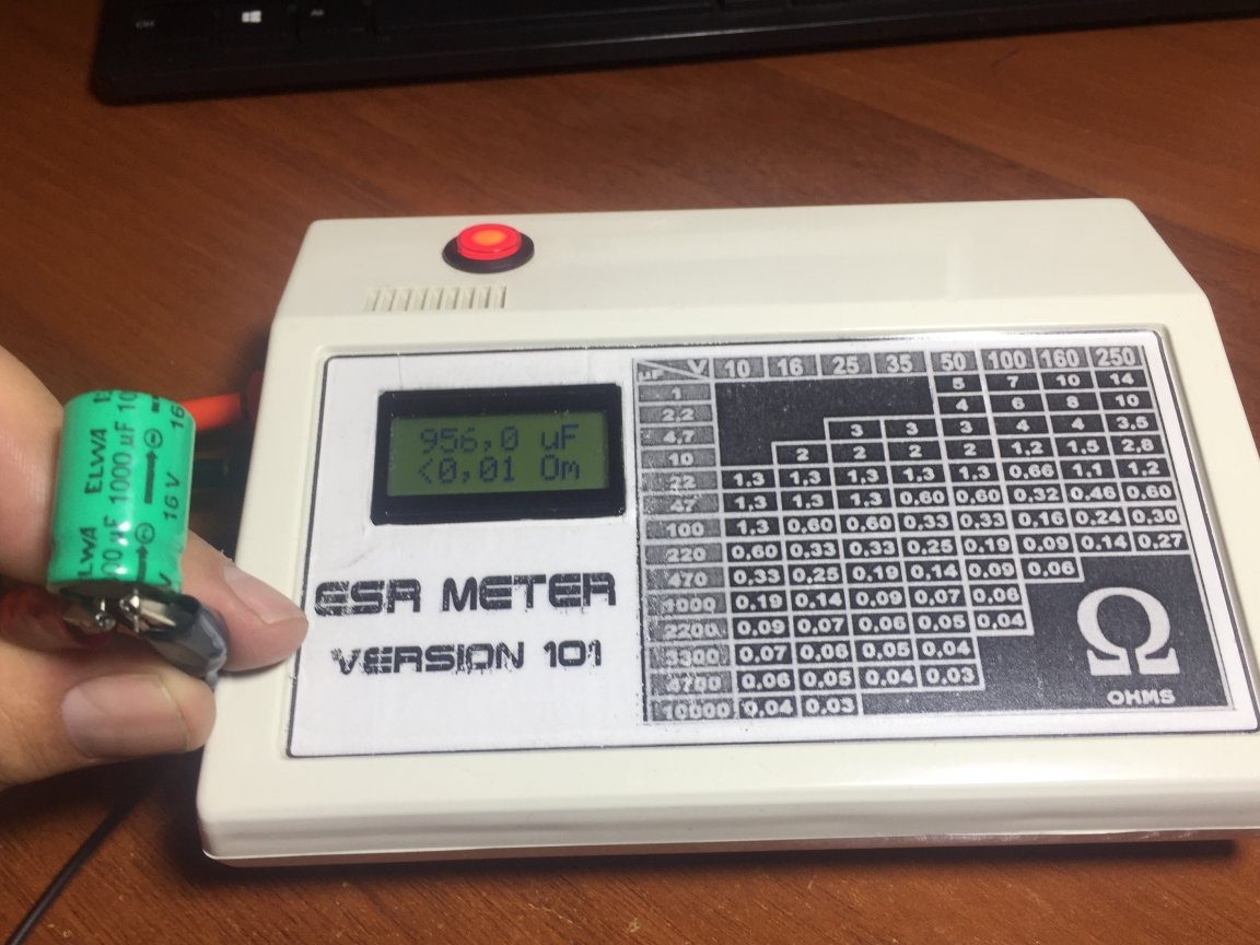
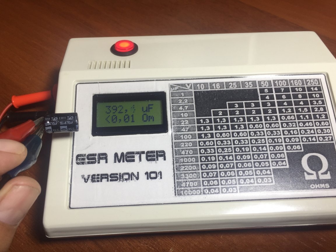
Now we need several capacitors, preferably new ones of good quality from 220 to 470 microfarads for different voltages, connect the capacitor to the output terminals and select the resistor R2 (in my case there is a multi-turn resistor), we get the readings on the LCD screen, it should approximately coincide with the capacitance of this capacitor . Next, we take a capacitor, for example, at 470 microfarads, we connect it to the device and select resistors R6, R9, R10 (on the board I have a lot of tuning tuning), we obtain ECR readings close to those indicated in the table,
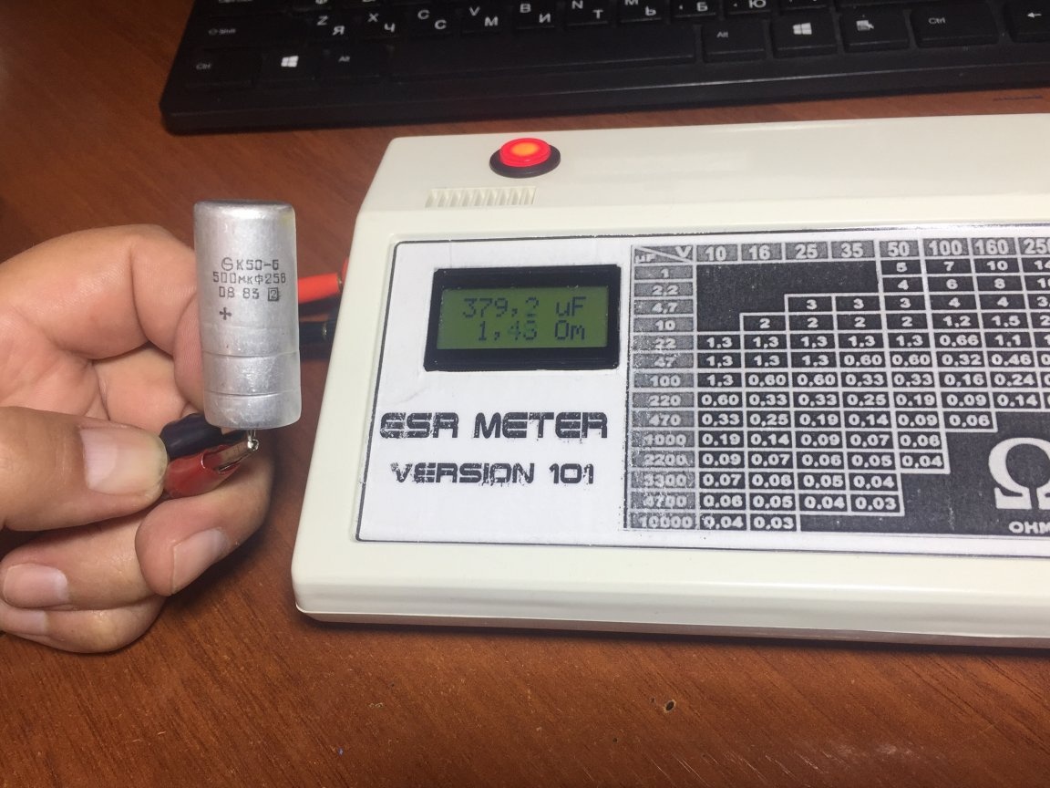
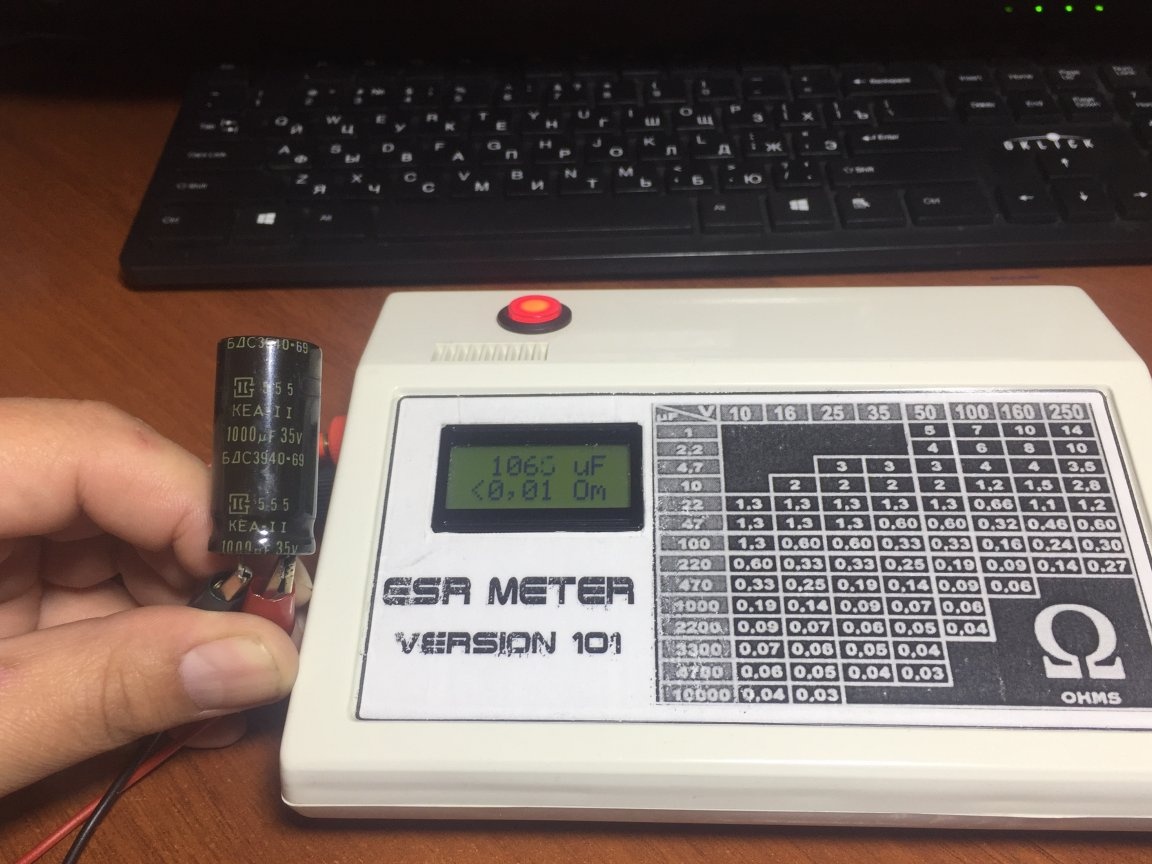
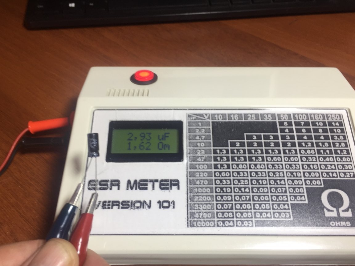
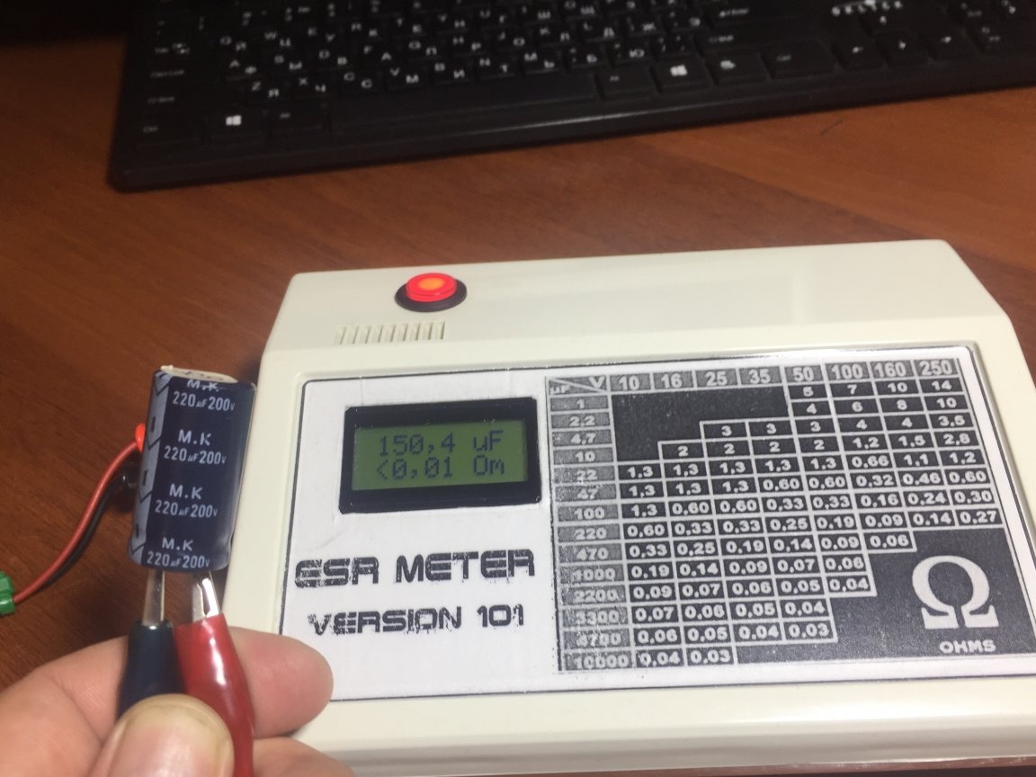
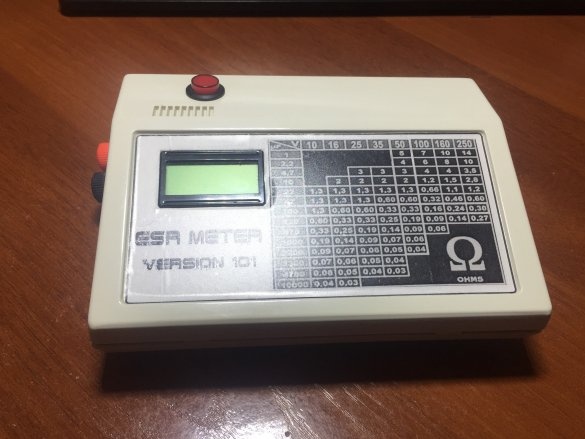
this table shows the maximum permissible parameters of the ECP. Now you can use capacitors from 1 microfarad. When I assembled this device, I was surprised how quickly and accurately measure the readings of capacitors. I took several capacitors and checked, immediately identified with increased internal resistance and reduced capacity, the photo shows this old Soviet electrolyte of the brand K50-6 500 μf 25 volts, the screen shows how he lost capacity and increased ESR.
Such a capacitor is immediately in the trash, it will not be able to work normally in high-frequency circuits. I also checked a few more, the photo shows all the parameters of the capacitors that I checked.
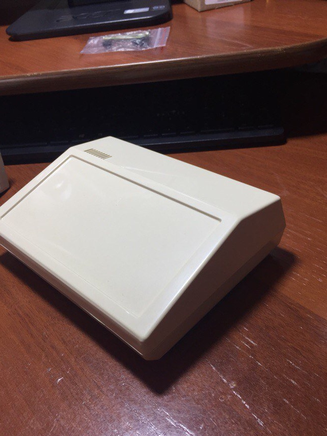
As a case, I used a ready-made instrument case that I bought at a local radio store
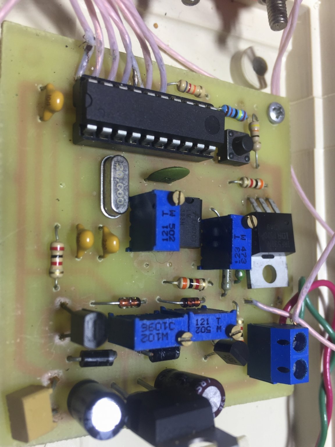
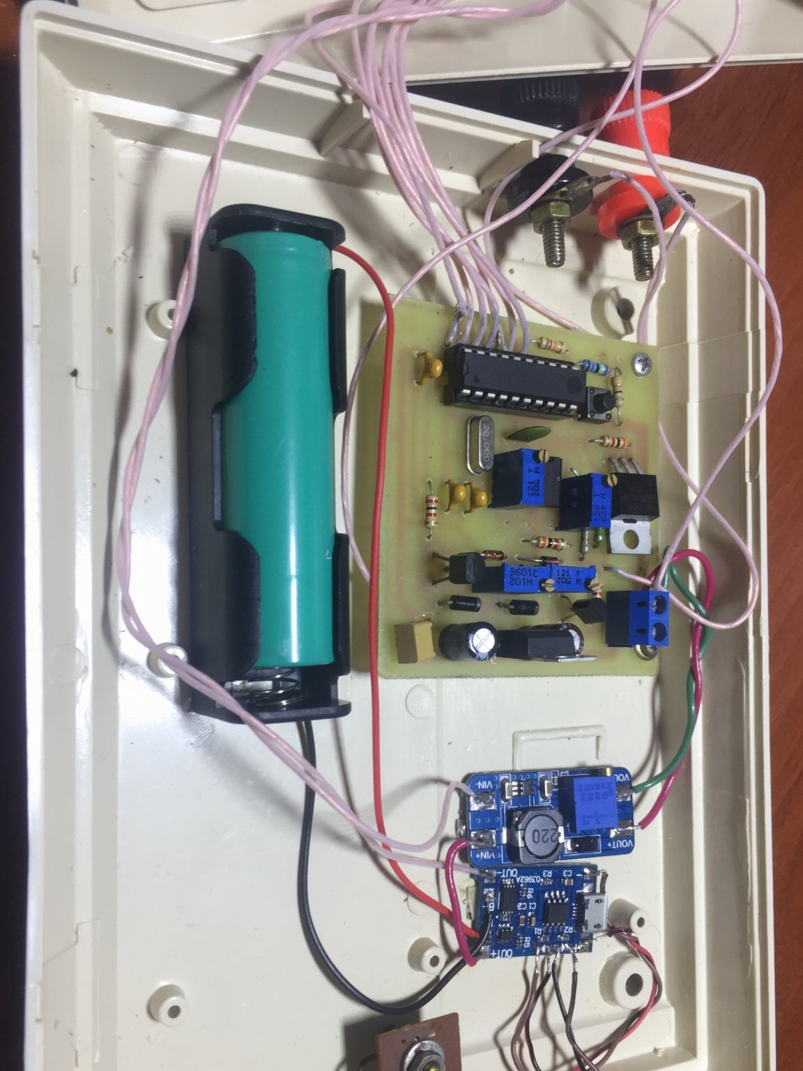
plenty of space in it, on the left is the board of the device itself
at the bottom of it is a lithium battery of 18650 format, which provides power to the device
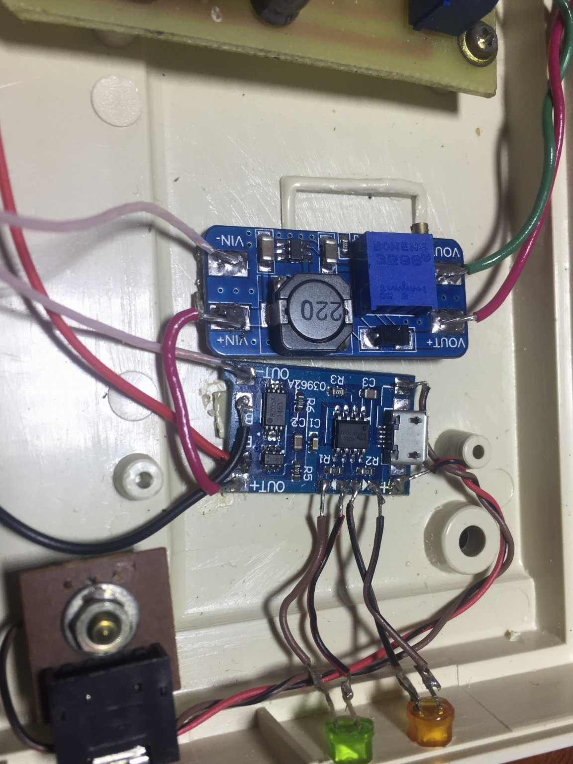
On the right is a voltage converter that raises the voltage to 9 volts.
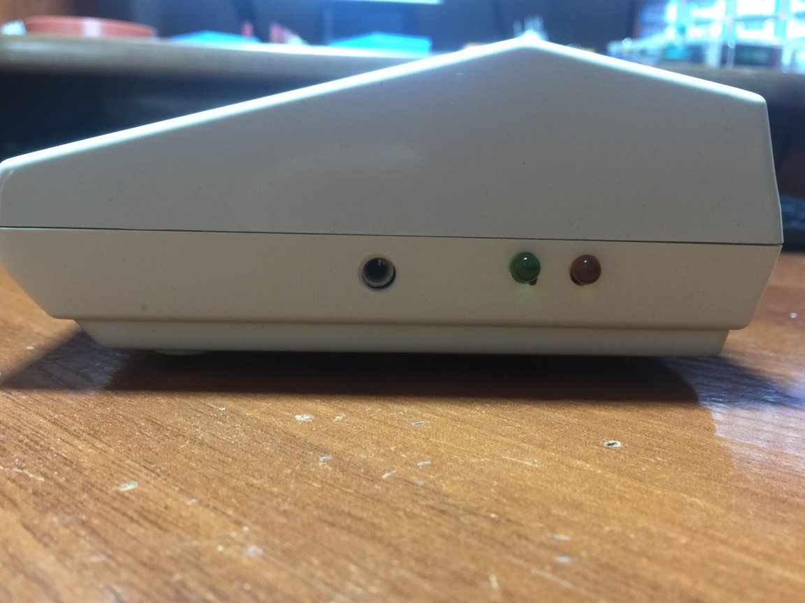
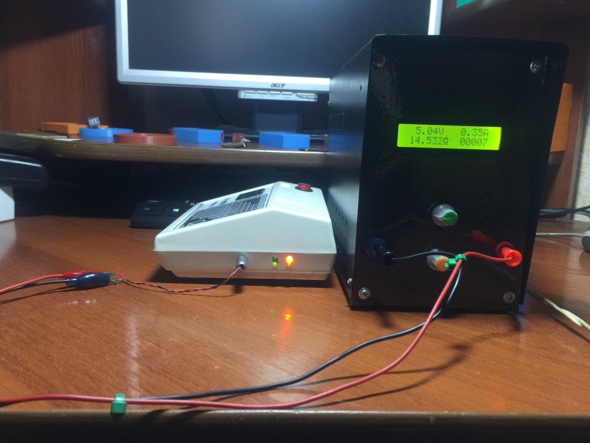
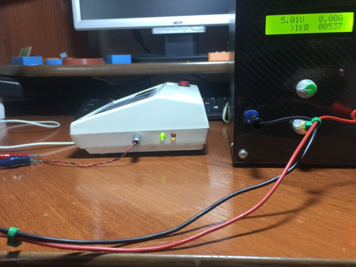
This voltage is supplied to the device circuitry and there it is already stabilizing up to 5 volts; a linear stabilizer L7805 in the TO220 housing can be used as a voltage stabilizer and can be replaced with a domestic analogue KR142EN5A (KREN5A). The device also provides a battery charging circuit on the TP4056 chip. Even if the battery runs out at an inopportune moment, then you can put it on charge and also take measurements. I put two LEDs on the side wall of the case for visual control of the charge. The orange charge is on, the green charge is over and there is also a 3.5 mm jack for connecting the charger, it may be an old charge from a 5 volt cell phone.
I am charging from my laboratory power supply for now.
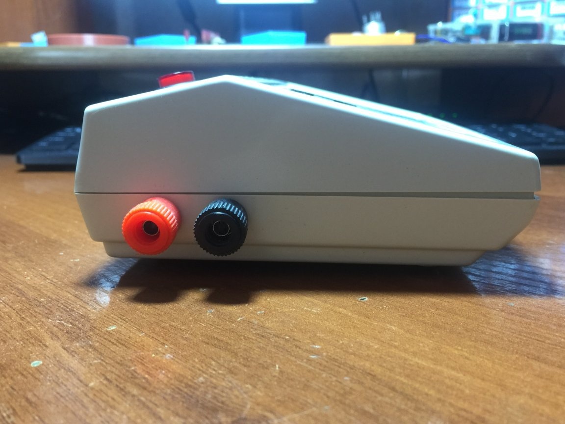
On the side wall of the housing on the left are banana-type connectors for connecting the tested capacitors.
On the front panel there is a table with the maximum allowable parameters of the ECP, a lcd display, a power button with an LED (although you can also do without it), I put the button in the breaker of the power supply of the converter so that the battery does not consume excess energy during downtime.
Such a device with ease will give odds to ready-made devices that are sold in China and you will agree that when you assemble a device you spend time and effort on manufacturing it, setting it up, and so on, it is much more pleasant than just going to the store and buying a ready-made one. More information about the device can be seen in the video below.
[media = https: //www.youtube.com/watch? v = pb3G04SuJ58]