

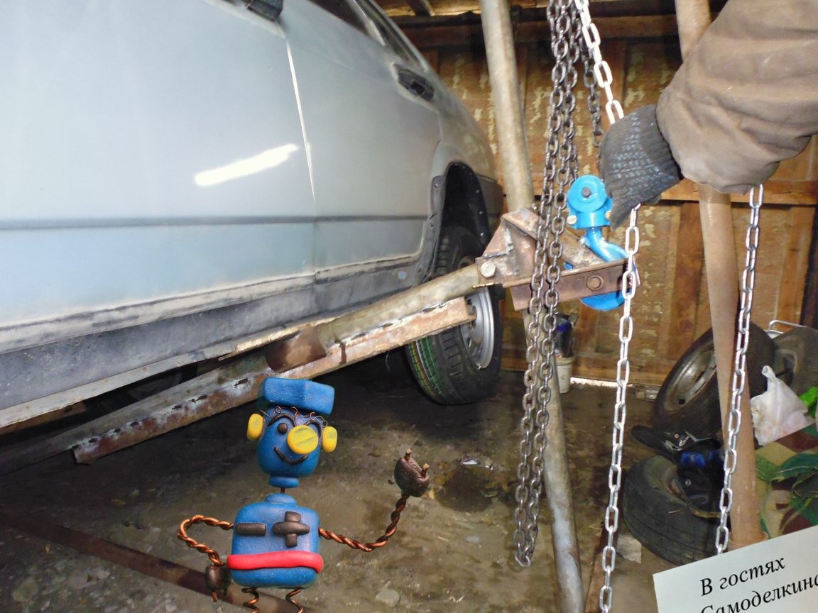
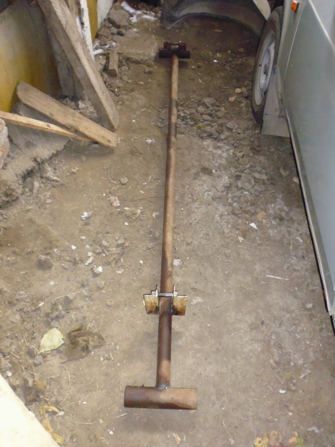
Good afternoon, in my instructions I will tell you how to make a lift for tilting the car, necessary for complex body repairs, etc.
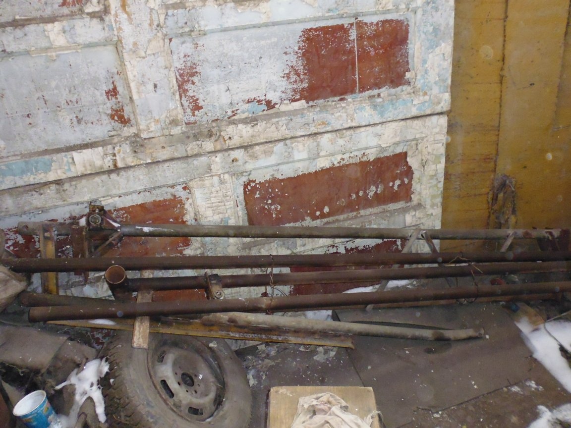
Folding lift for easy storage.
The operation of the lift is provided with little effort, but an electric variant is also possible, depending on the equipment used.
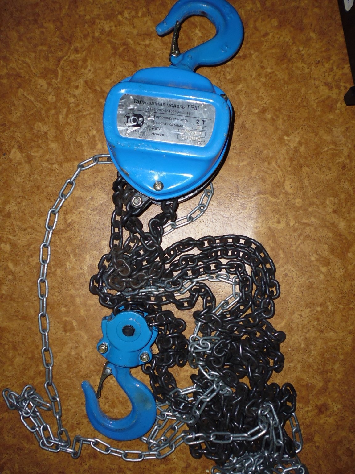
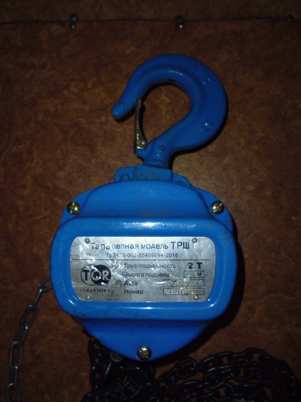
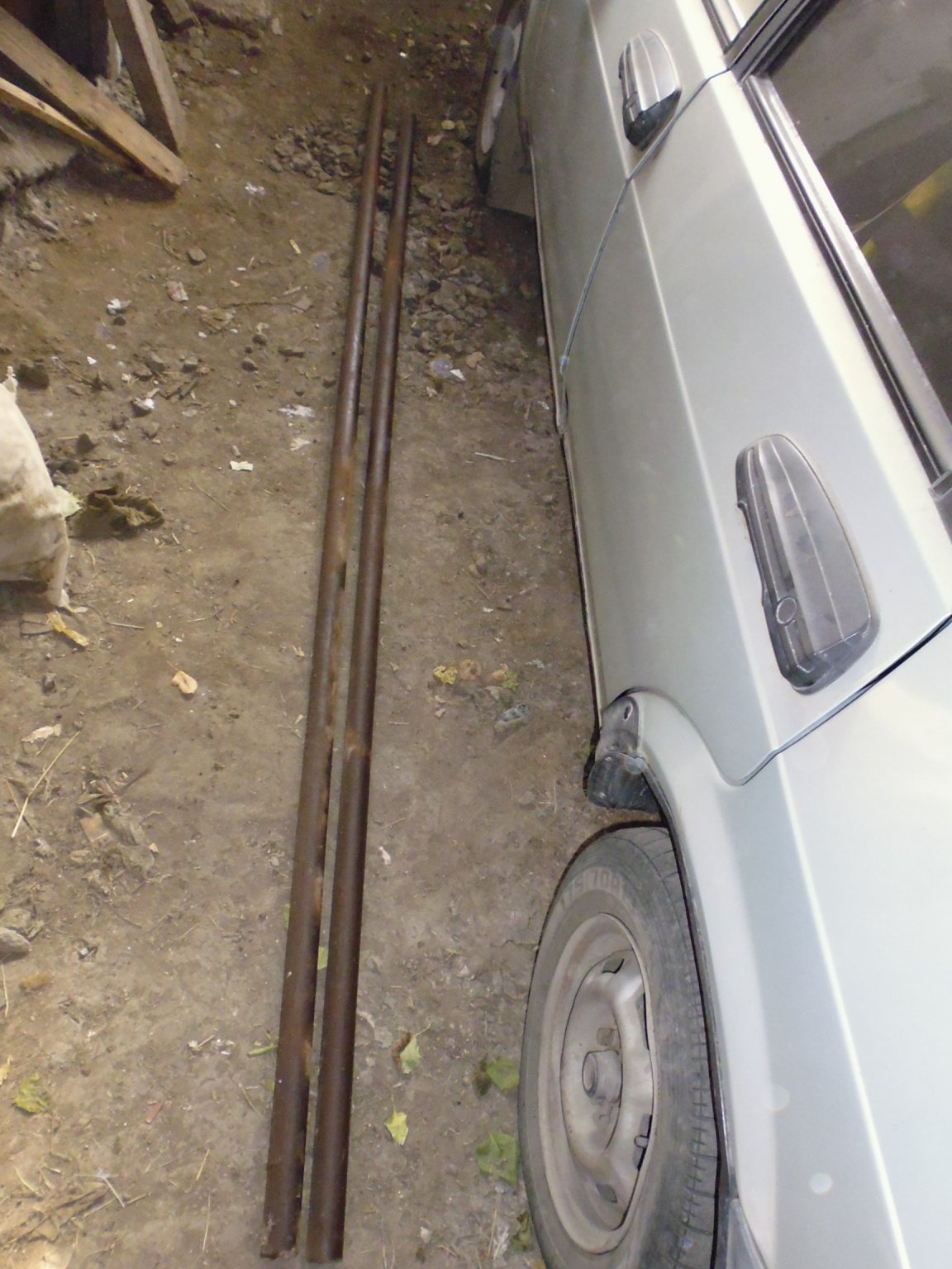
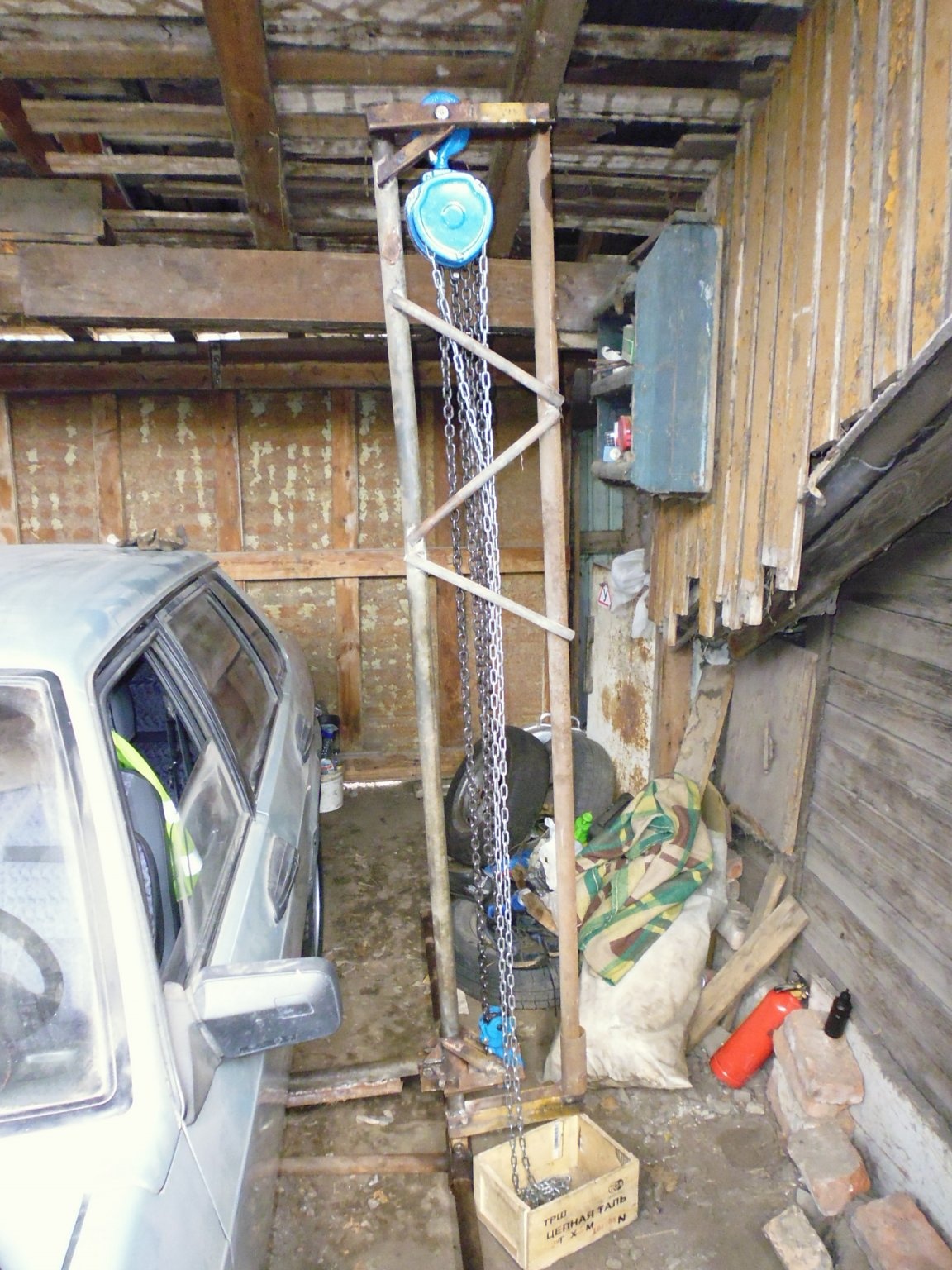
The tilt of the machine is carried out by hand hoist with a maximum load of 2 tons with a drive chain of 2 meters (there are also electric hoists on the market, but more expensive). In the initial version, the lifting beam consisted of one pipe, but in the process of operation it had to be strengthened - to increase rigidity (an option appeared of two pipes with transverse crossbars).
All other machine parts were made. do it yourself from improvised means.
Materials and tools that I used:
Material List:
1. Tal maximum load 2 tons with a drive chain of 2 meters;
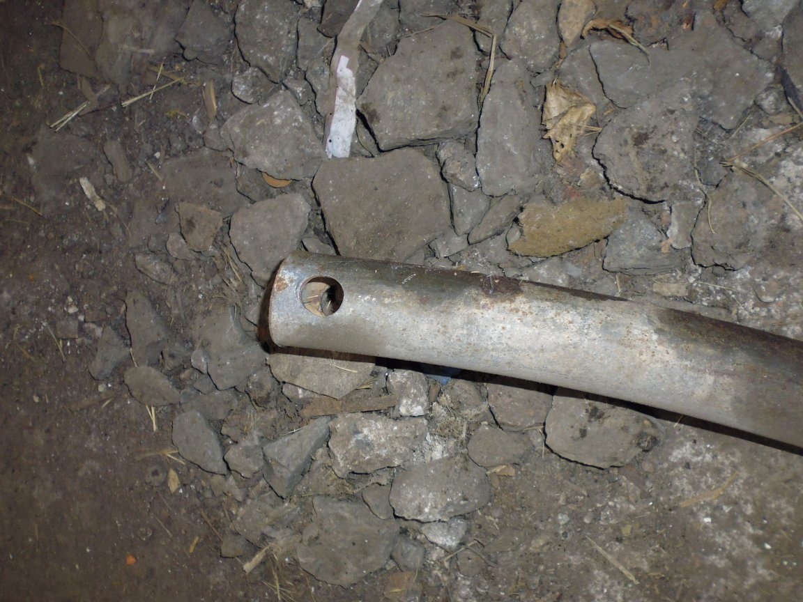
2. Steel water pipe ½ inch with an outer diameter of 21 mm.
3. Steel pipe 1 ¼ inch with an outer diameter of 42 mm.
4. Steel water pipe 2 inches with an outer diameter of 60 mm.
5. Corner 50x50;
6. Corner 40x40;
7. Corner 30x30;
8. Steel sheet 5 mm thick;
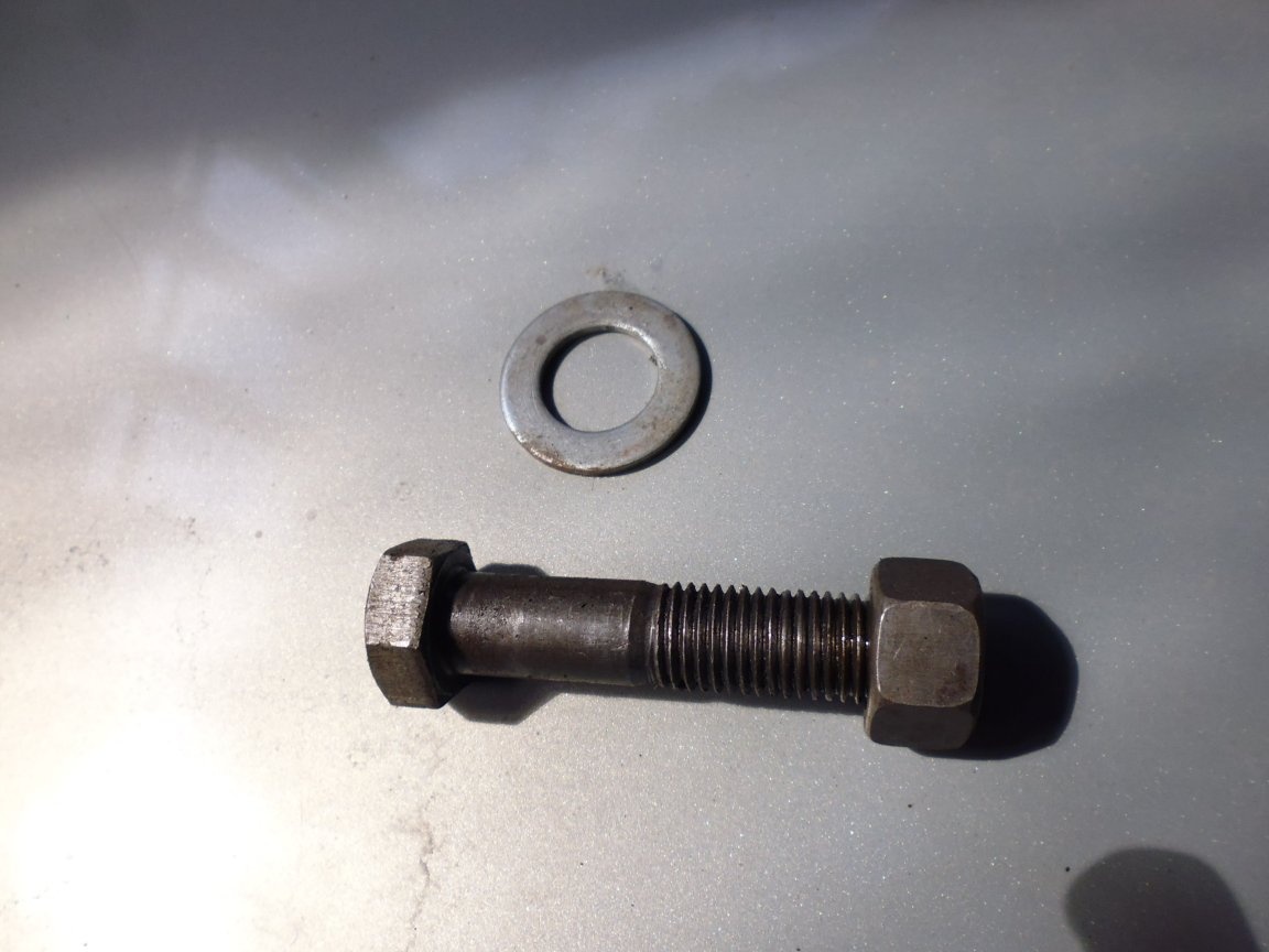
9. Bolts, washers and nuts М16;
Tool List:
1. Drilling machine;
2. Welding transformer;
3. The grinder;
4. Metal grinding machine;
5. Drills for metal;
6. Wrenches;
7. Clamp;
8. The line;
9. Roulette;
10. The hammer;
The manufacturing process of the elevator for tilting the machine:
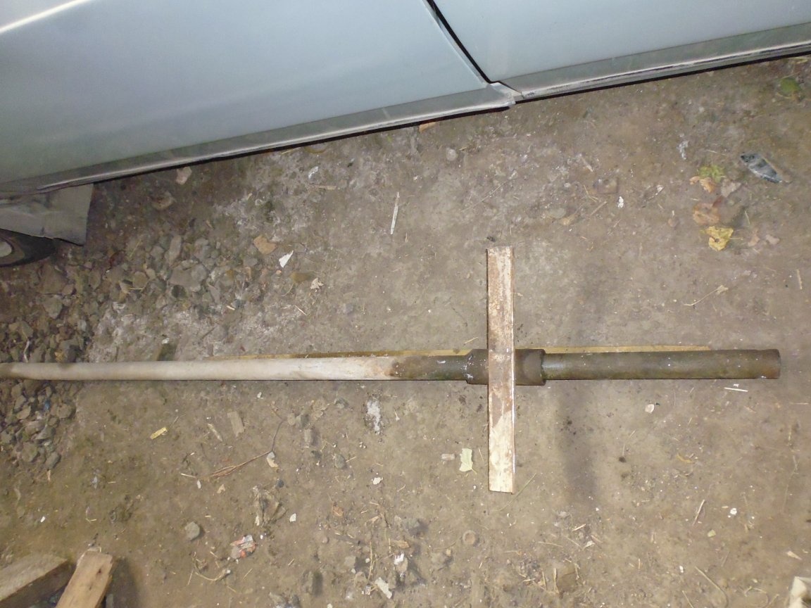
Step One: Making blanks of the lifting carriage.
1. From a ½ inch water pipe with an outer diameter of 21 mm, we cut the blank of the lift finger with a length of 60 mm with a grinder.
2. From a 2-inch water pipe with an outer diameter of 60 mm, we cut a blank of the guide body of the lifting carriage with a length of 150 mm with a grinder.
3. From the corner 50x50 grinder we cut out two blanks of the shelf of the finger of the lift with a length of 185 mm. On the drilling machine in the shelf we make holes with a diameter of 17 mm.
4. From the corner 40x40 grinder we cut out two blanks for an eye 60 mm long. On the drilling machine in the eyes we make holes with a diameter of 17 mm.
5. From the corner 30x30 with a grinder we cut out two blanks for stopping the shelf of the elevator finger.
6. From the plate with a thickness of 5 mm, we cut out two triangles with a grinder to stop the eye.
7. With a metal grinder on the workpieces, we clean the places for welding.
Step Two: Making blanks of the swing beam.
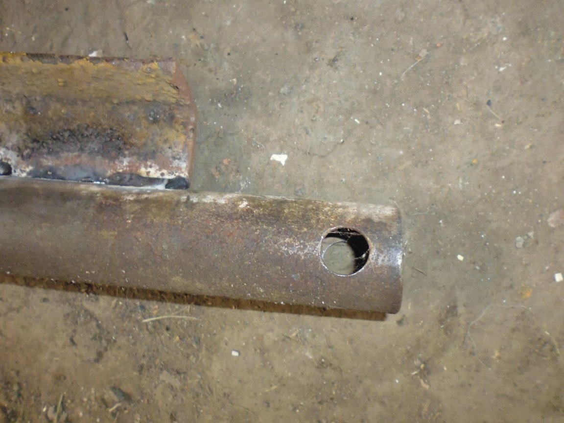
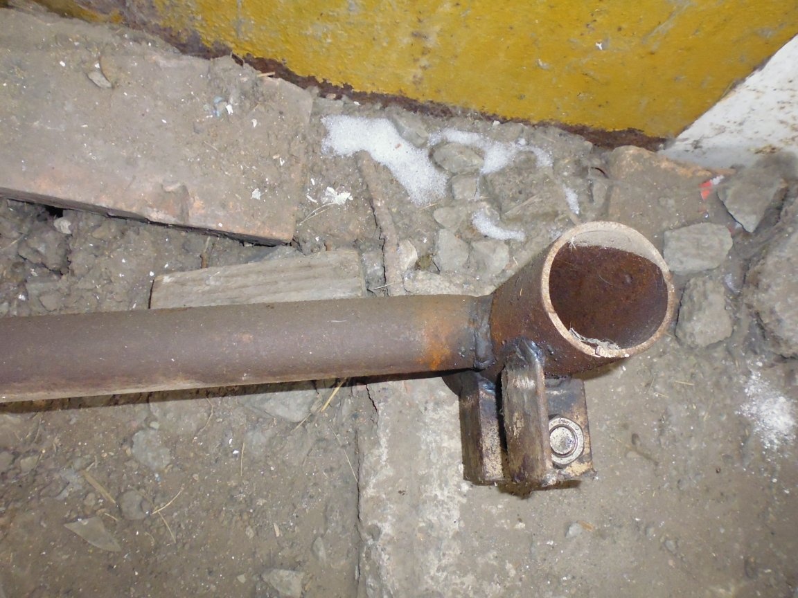
1. From a 1 ¼ inch water pipe with an outer diameter of 42 mm, we cut a blank of a turning beam with a length of 1720 mm with a grinder. On a drilling machine from two opposite sides we make holes with a diameter of 17 mm.
2. From the corner 40x40 grinder we cut a stiffener 1400 mm long.
3. With a metal grinder on the workpieces, we clean the places for welding.
Step Three: Making blanks of the thrust beam.
1. From a 1 ¼ inch water pipe with an outer diameter of 42 mm, we grind a longitudinal blank of the thrust beam with a length of 2000 mm.
2. From a 2-inch water pipe with an outer diameter of 60 mm, we cut the two transverse blanks of the guide thrust beam with a length of 200 mm with a grinder.
3. From the corner 40x40 grinder we cut two blanks for the eyes of the swivel beam with a length of 120 mm. On the drilling machine in the eyes we make holes with a diameter of 17 mm.
4. From the corner 40x40 grinder we cut two blanks for the eyes of the lifting beam with a length of 60 mm. On the drilling machine in the eyes we make holes with a diameter of 17 mm.
5. With a metal grinder on the workpieces, we clean the places for welding.
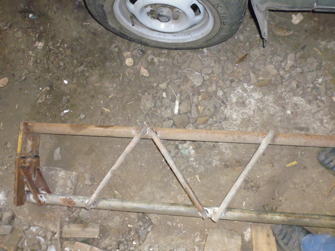
Fourth step: Making blanks of the lifting beam.
1. From a 1 ¼ inch water pipe with an outer diameter of 42 mm, we grind the main workpiece of the lifting beam with a length of 2200 mm. On a drilling machine, from one end we make a hole with a diameter of 17 mm.
2. From a 1 ¼ inch water pipe with an outer diameter of 42 mm, we grind the second blank of the lifting beam with a length of 1700 mm.
3. From a ½-inch water pipe with an outer diameter of 21 mm, we cut three billets of the beam of the lifting beam with a length of 400 mm with a grinder.
4. From a ½ inch water pipe with an outer diameter of 21 mm, we cut the blank of the finger of the lifting beam with a length of 60 mm with a grinder.
5. From the corner 40x40 grinder we cut four blanks of the upper and lower crossbeams of the lifting beam 320 mm long. On a drilling machine in the upper two crossbars we make holes with a diameter of 17 mm.
6. From the corner 30x30 with a grinder we cut out two blanks to stop the upper crossbar.
7. With a metal grinder on the workpieces, we clean the places for welding.
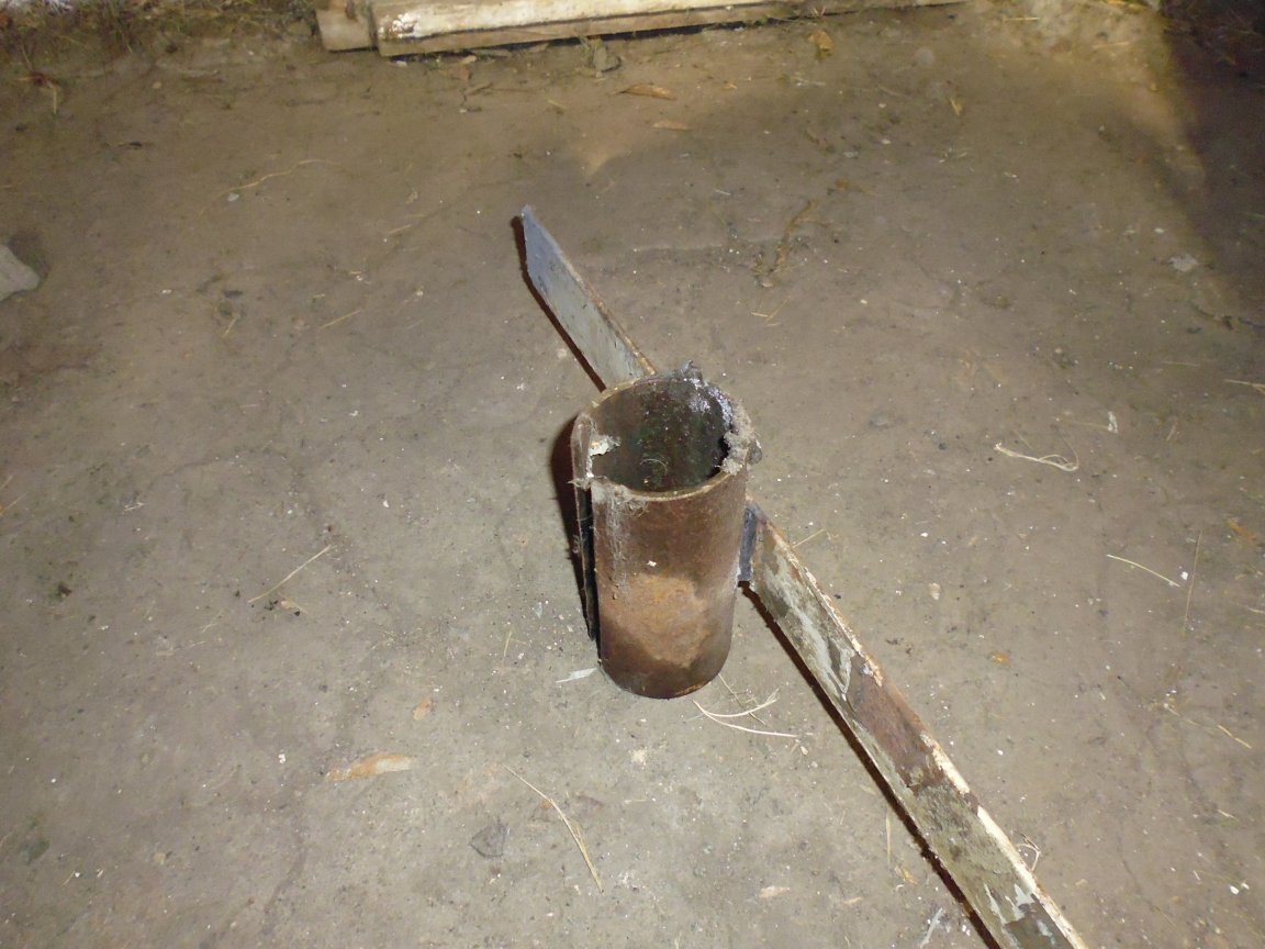
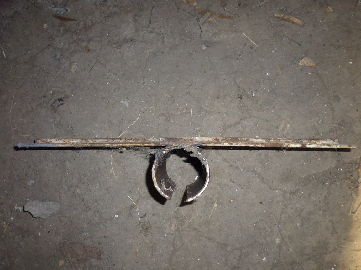
Step Five: Making Floating Support Billets
1. From a 2-inch water pipe with an external diameter of 60 mm, we cut a blank with a grinder of a floating support of 100 mm long, using a grinder, we cut a groove 6-7 mm wide along the workpiece with a grinder.
2. From a 40x40 corner with a grinder, we cut a blank of the heel of a support 300 mm long., Cut a part of the corner shelf so that a protruding edge of about 5 mm remains.
3. With a metal grinder on the workpieces, we clean the places for welding.
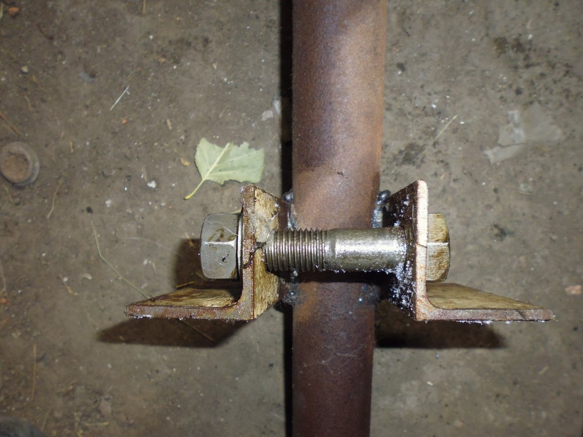
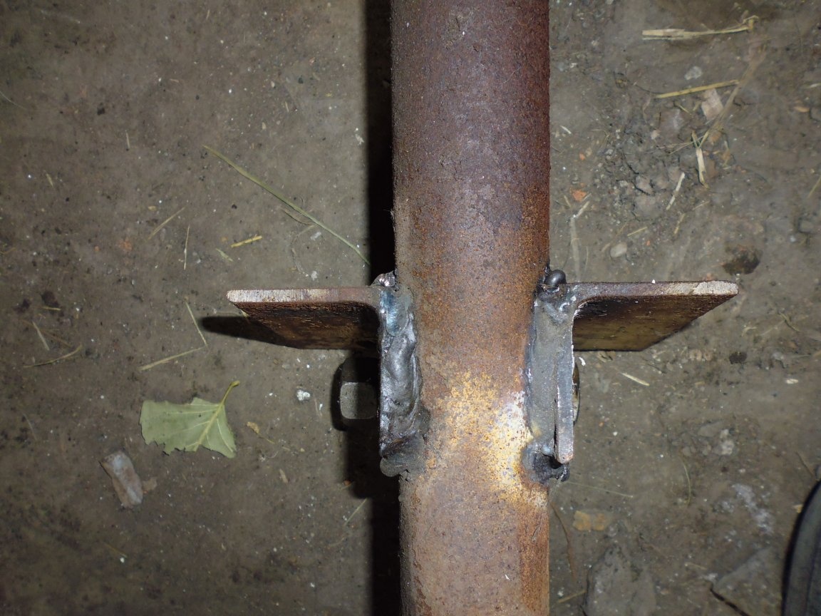
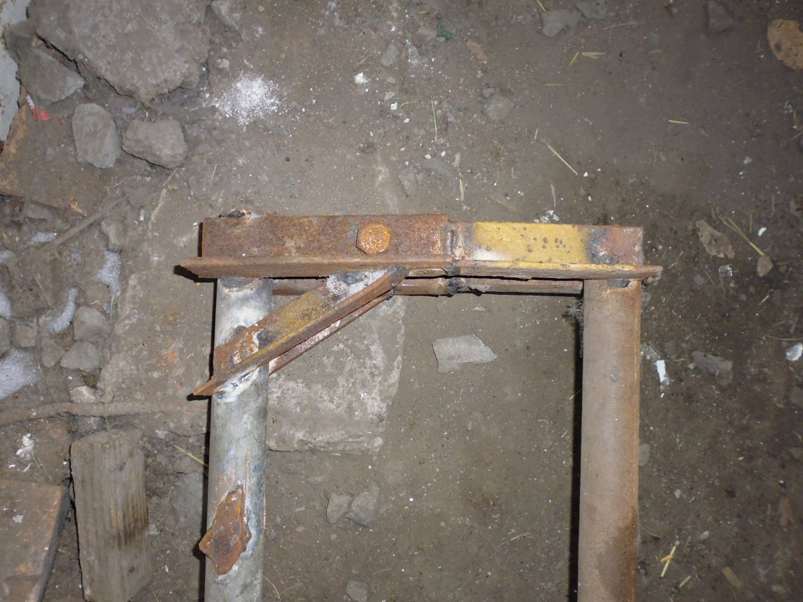
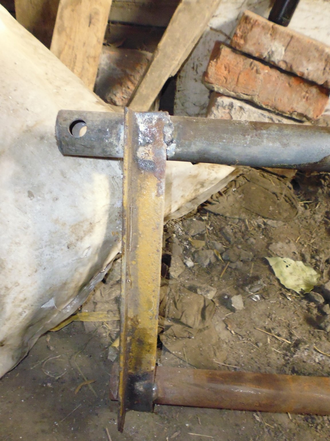
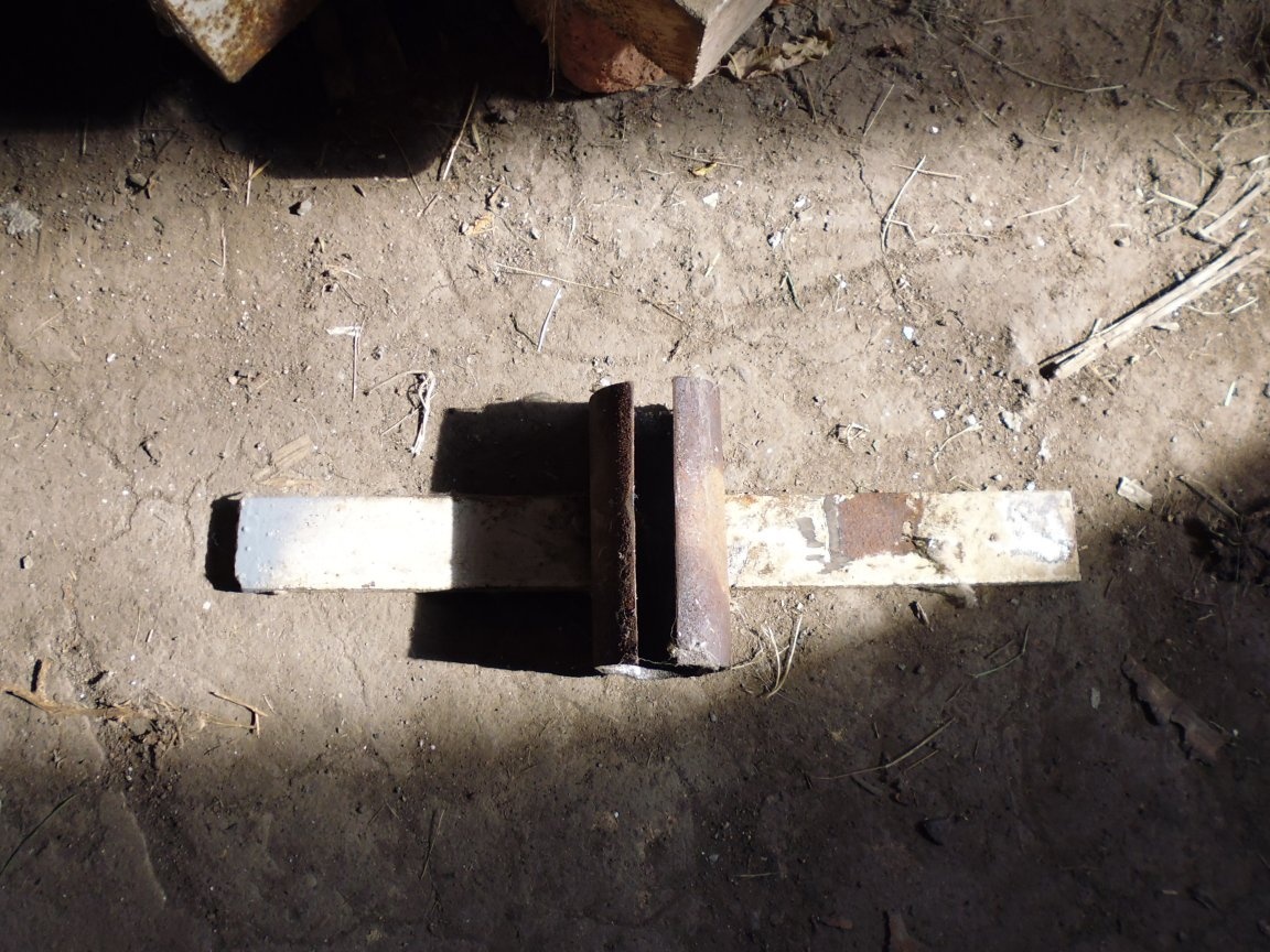
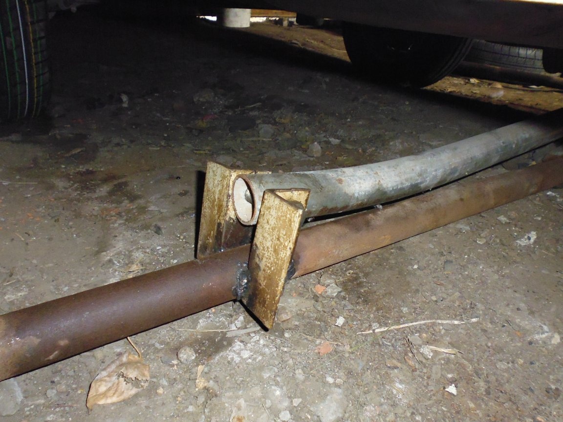
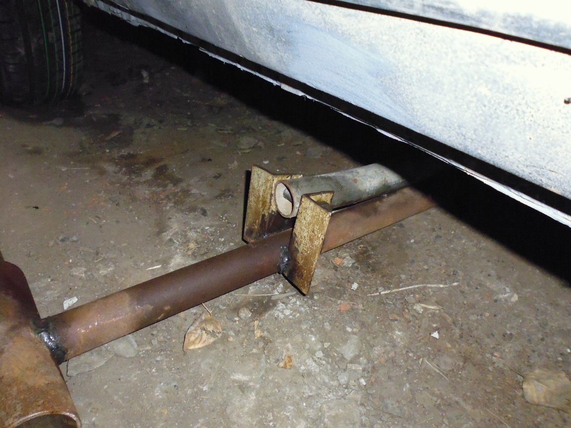
Sixth step: Assembling the lifting carriage.
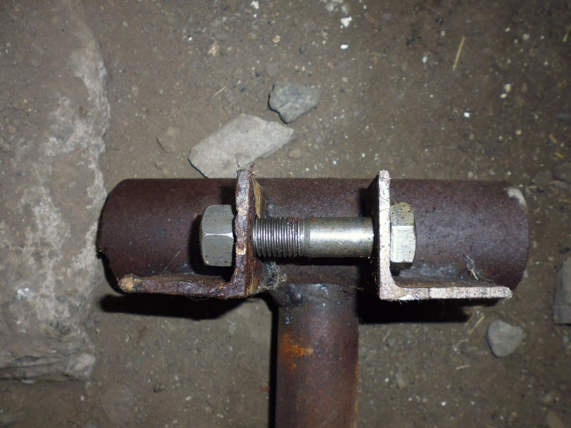
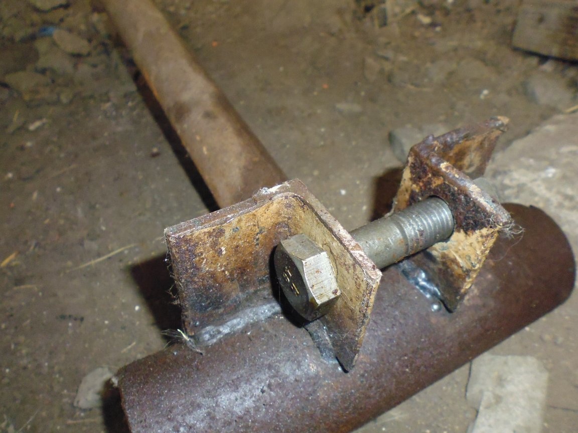
1. Combine the hole of the finger of the lifting carriage with the holes of the shelves of the finger so that the shelves are located to the right and left of the edges of the finger, install the M16 bolt in the hole and clamp it with a nut.
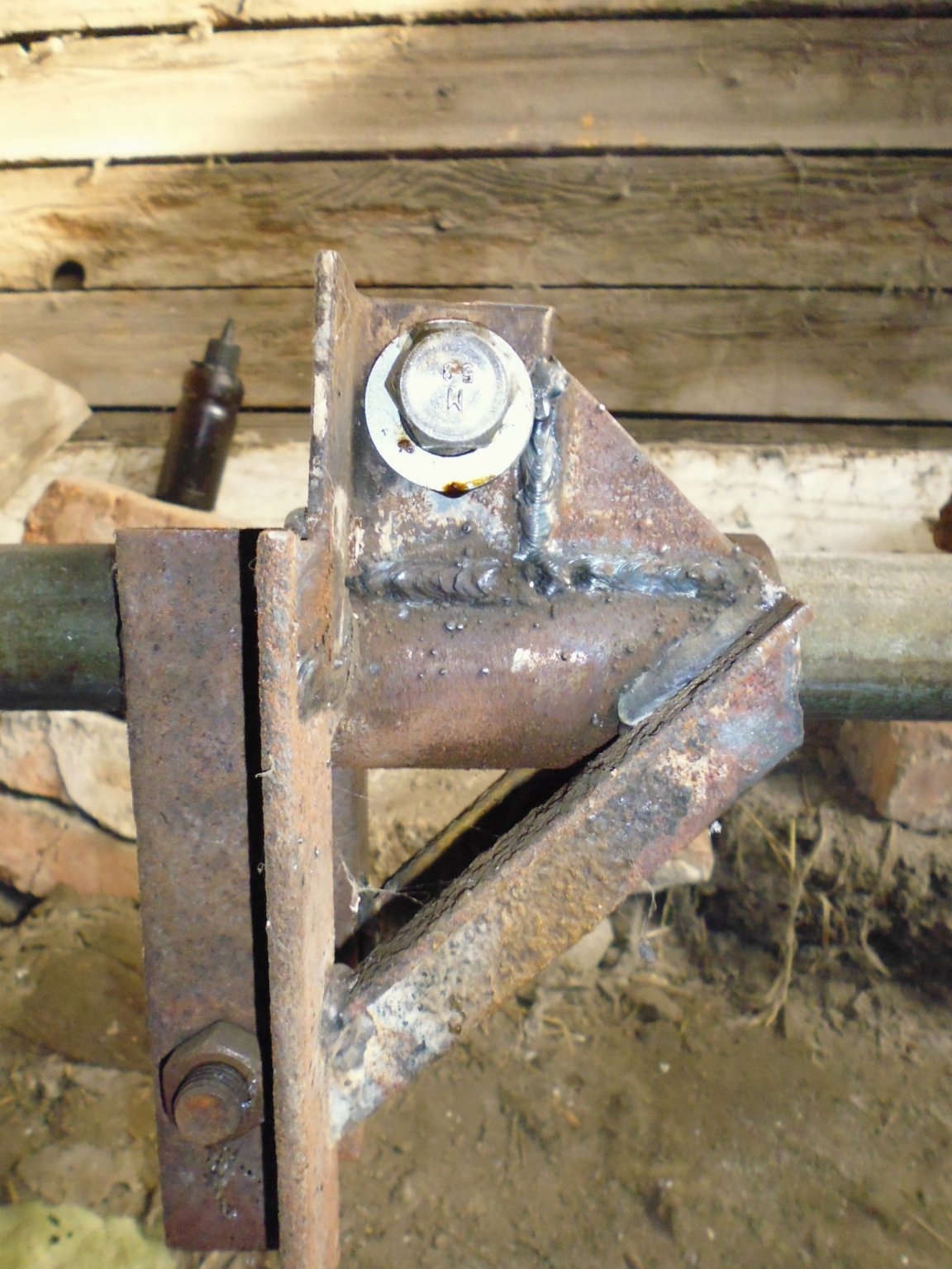
2. Align the edge of the guide housing of the lifting carriage with the shelves at an angle of 90 degrees, then weld the guide body and the finger to the shelves of the lifting carriage.
3. On the opposite side from the shelves of the finger to the housing of the lifting carriage, we weld two eyes, combining with the edge of the shelves, between the eyes we provide a distance of 47 mm and the alignment of the holes.
4. On the opposite side of the eyes we weld the eye lugs.
5. Under the shelf of the lifting carriage, we weld the stops of the shelf at an angle of 45 degrees.
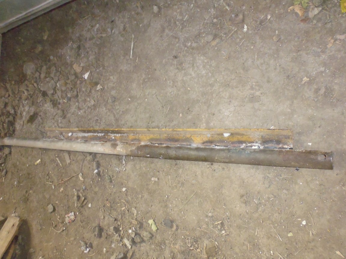
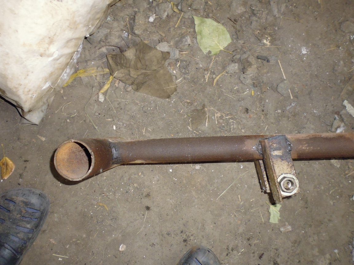
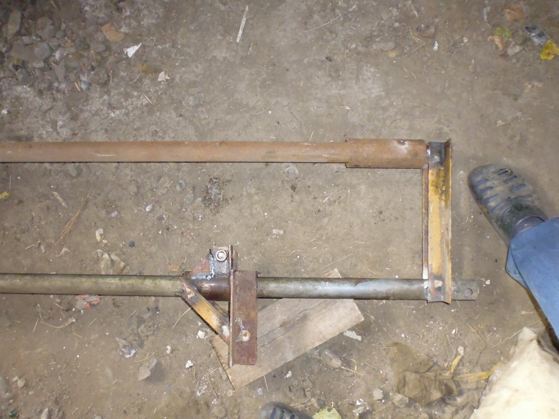
Seventh step: Assembling the swing beam.
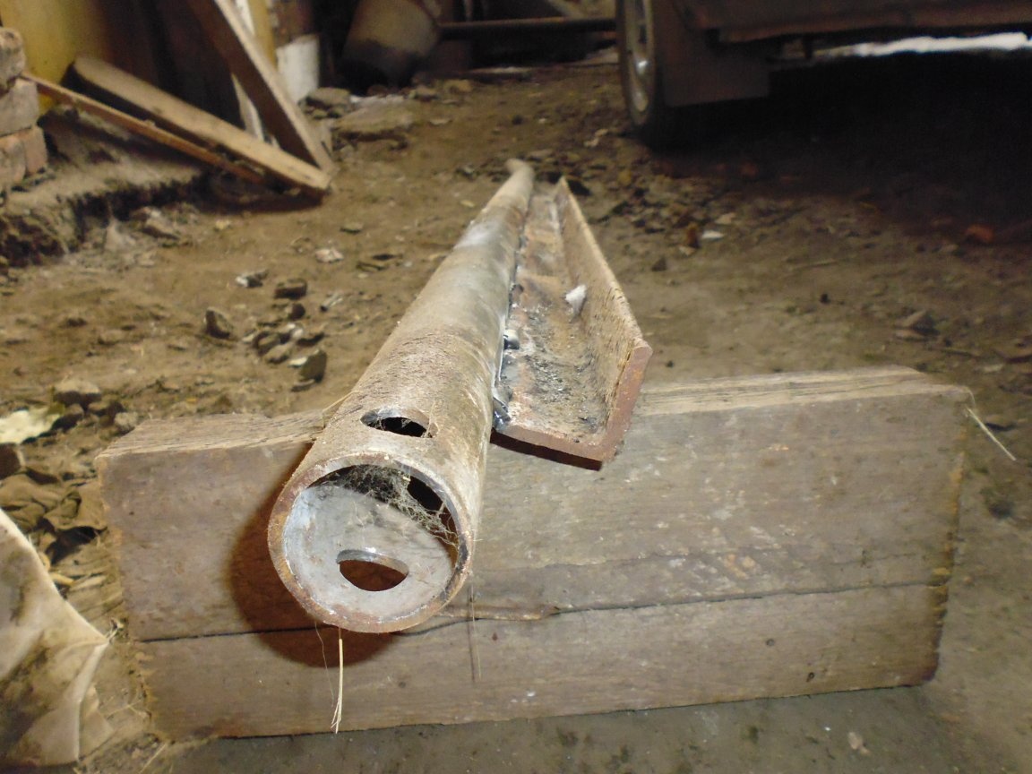
1. To the pivot beam, on the reverse side of the stop, we weld a stiffener with a discontinuous seam, retreating 100 mm from the edge of the beam.
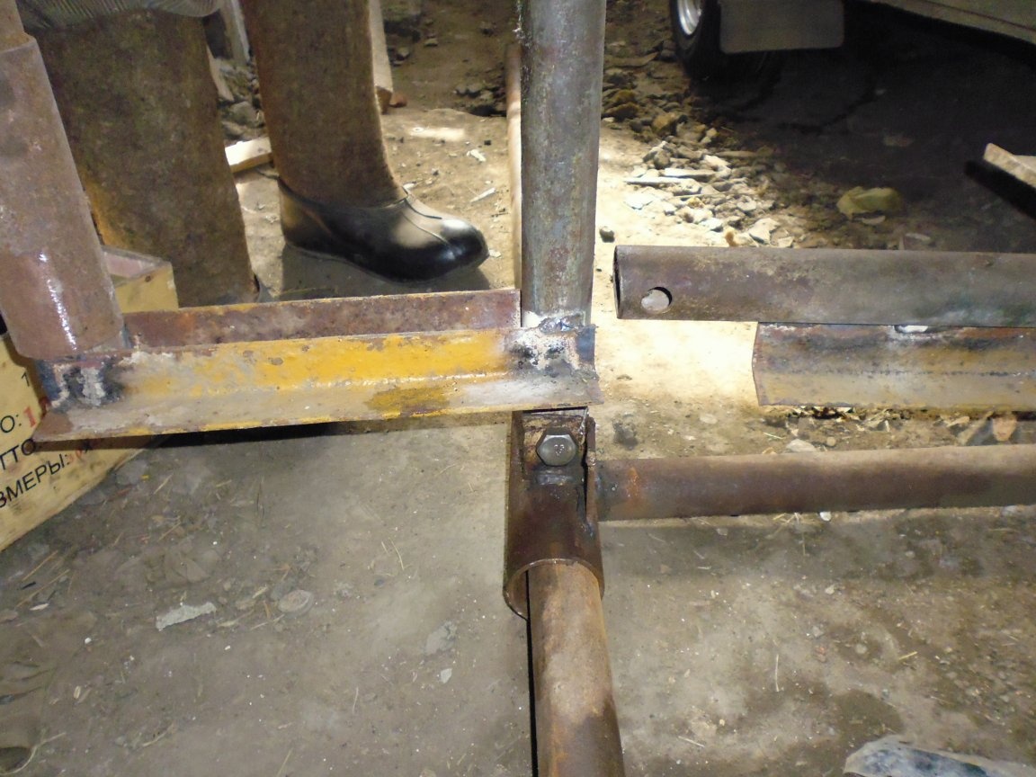
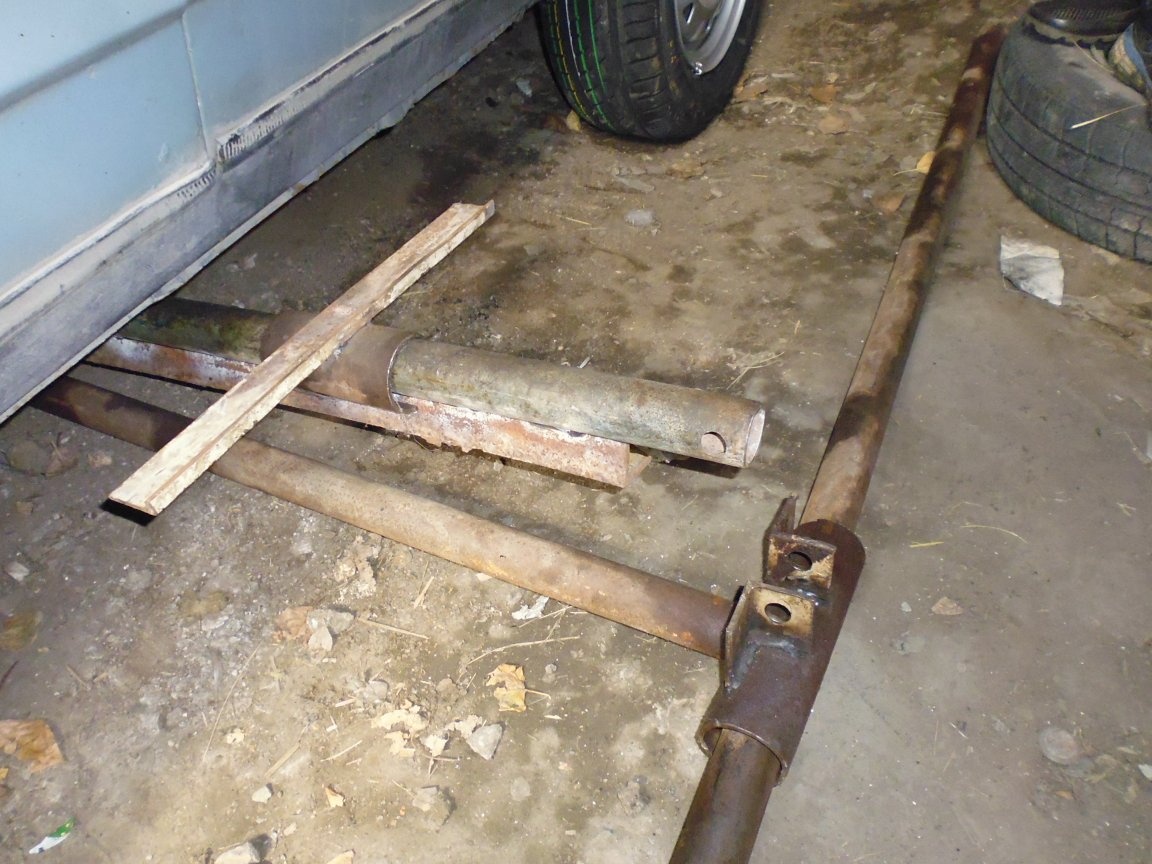
Step Eight: Assemble the Thrust Beam.
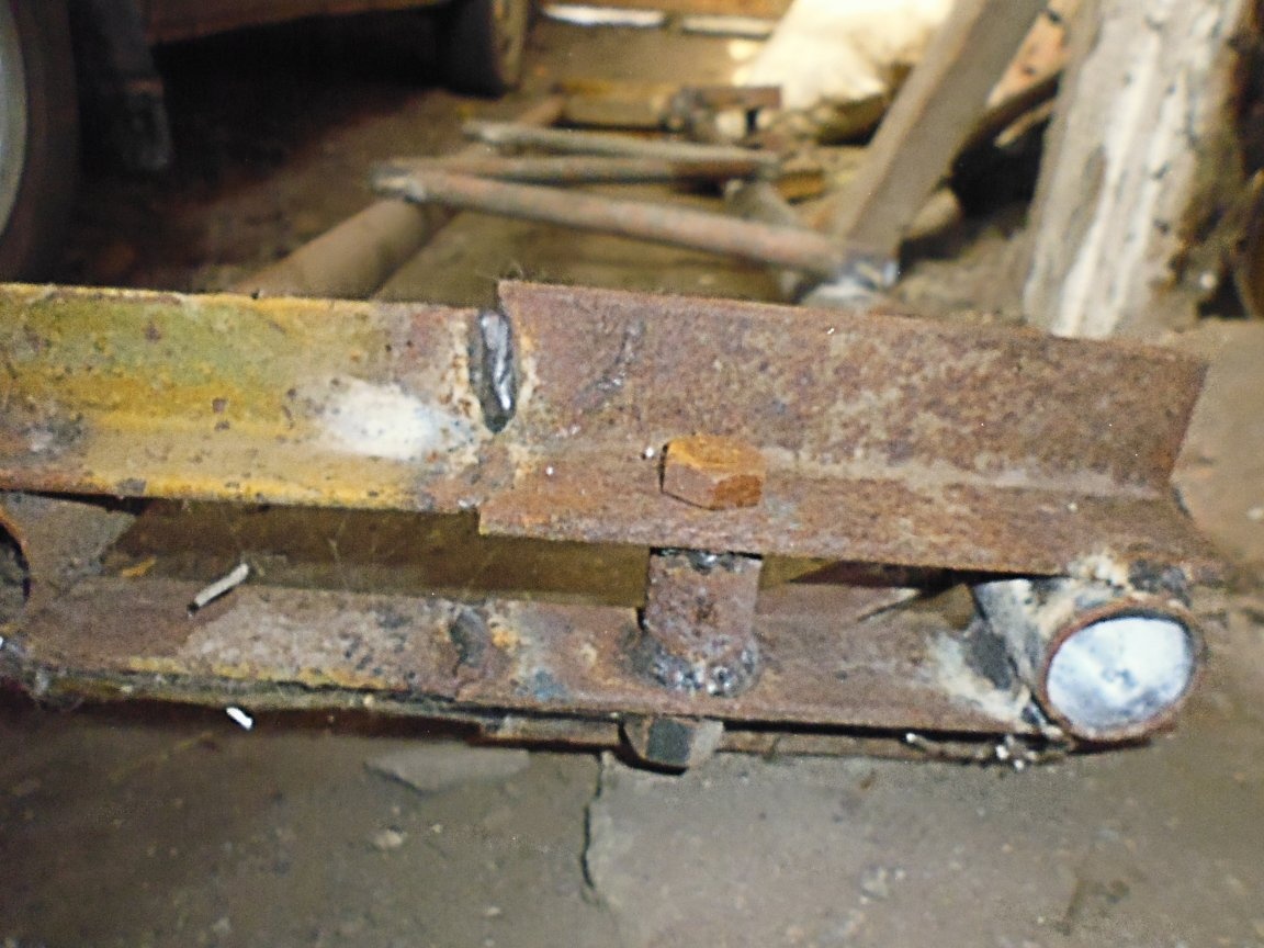
1. At the ends of the thrust beam parallel to each other, we weld the guides.
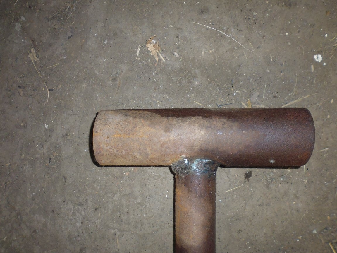
2. On the thrust beam perpendicular to the guides, retreating 305 mm from the axis of the first guide, we weld two eyes of the swivel beam, between the eyes we provide a distance of 47 mm and alignment of the holes.
3. On the second guide rail perpendicular to the thrust beam, we weld two eyes of the lifting beam, between the eyes we provide a distance of 47 mm and the alignment of the holes.
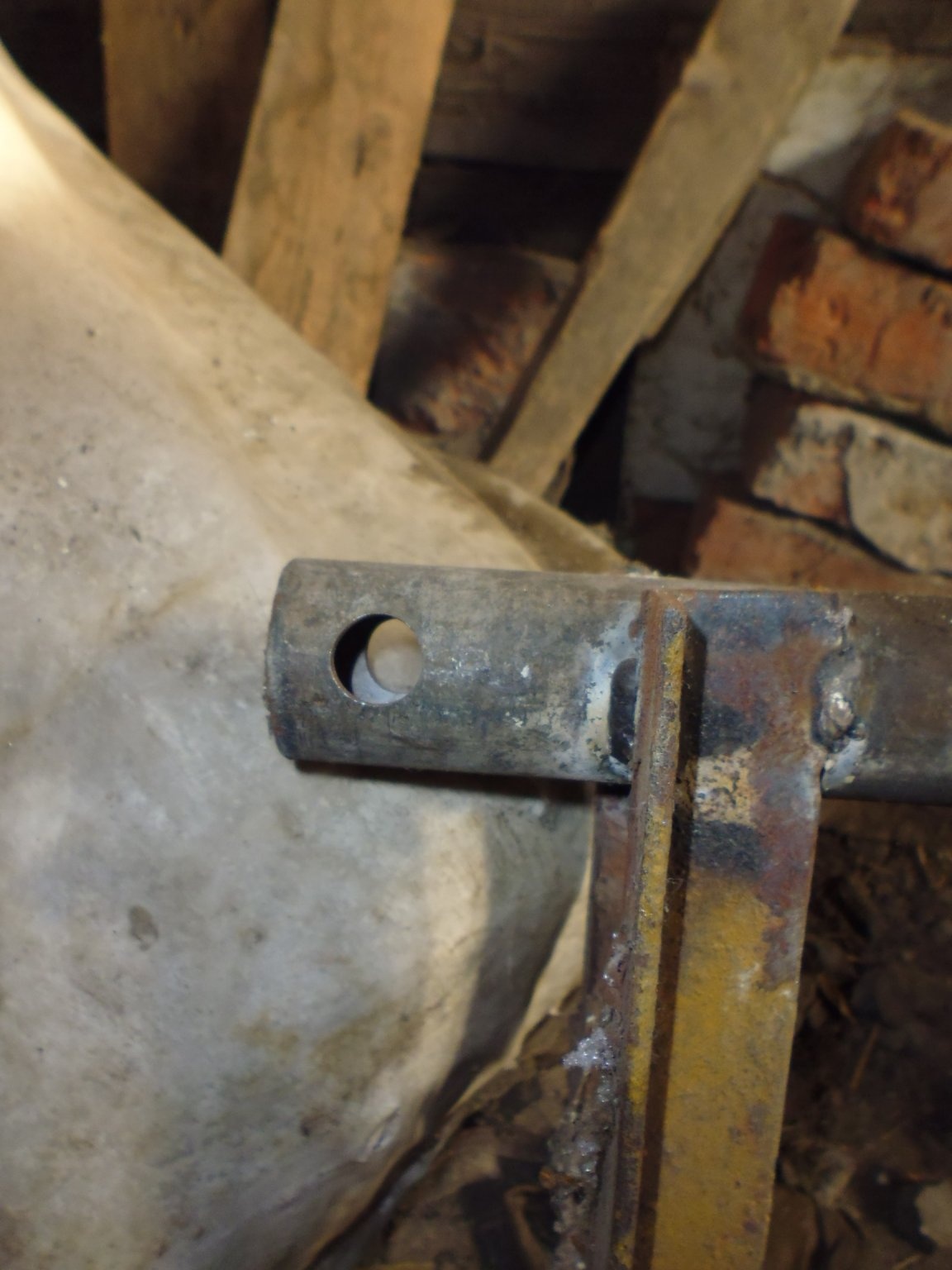
Step Nine: Assembling the lifting beam.
1. Combine the hole of the finger of the lifting beam with the holes of the upper crossbar so that the shelves are located to the right and left of the edges of the finger, install the M16 bolt in the hole and clamp it with a nut.
2. Align the upper beams along the edge with the main and second lifting beams at an angle of 90 degrees, then weld the upper beams and a finger to the lifting beams.
3. Install the lifting carriage on the main lifting beam.
4. Align the lower beams along the edge with the second lifting beam at an angle of 90 degrees, then weld the lower beams to the lifting beams.
5. On the main and second lifting beam, on the one hand in the upper part, stepping back from the edge of 300 mm, welded with a ladder one after the other at an angle of 45 degrees three transverse stops.
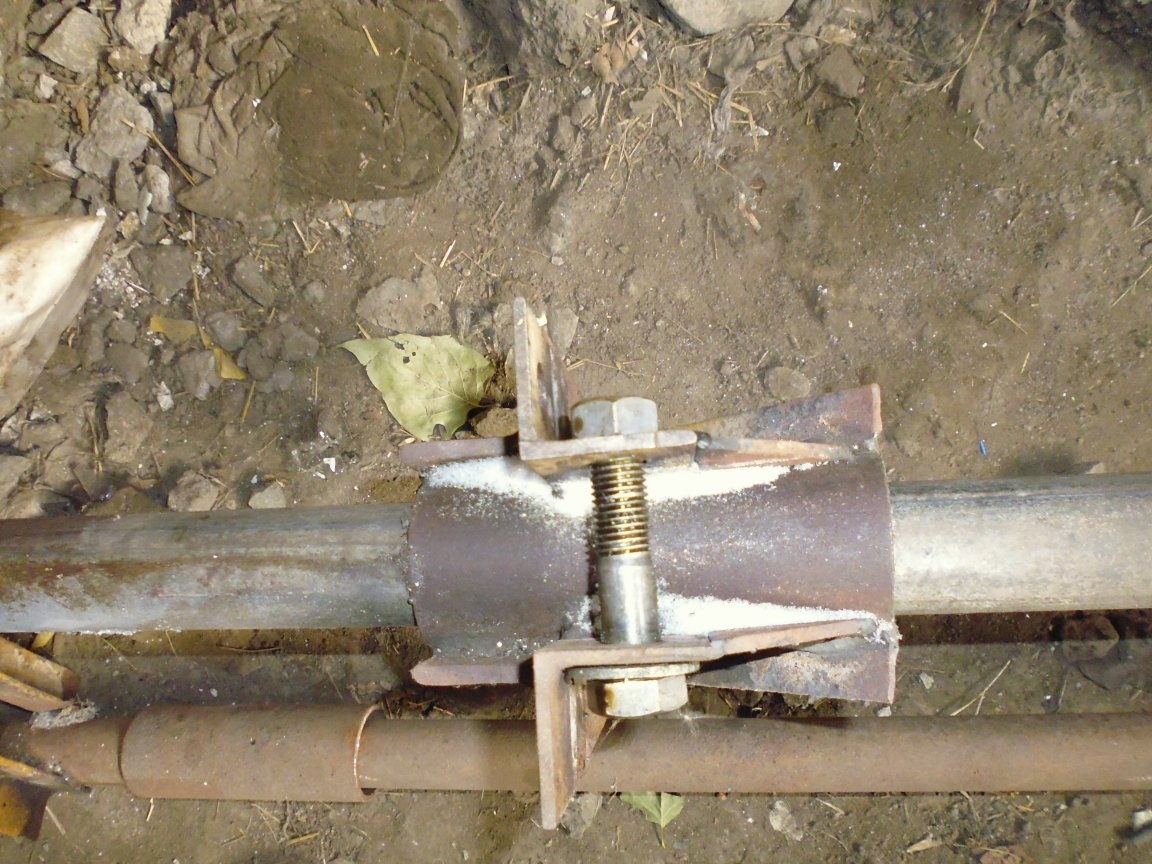
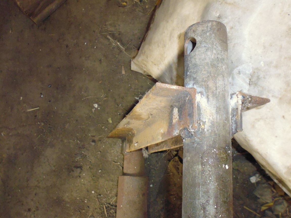
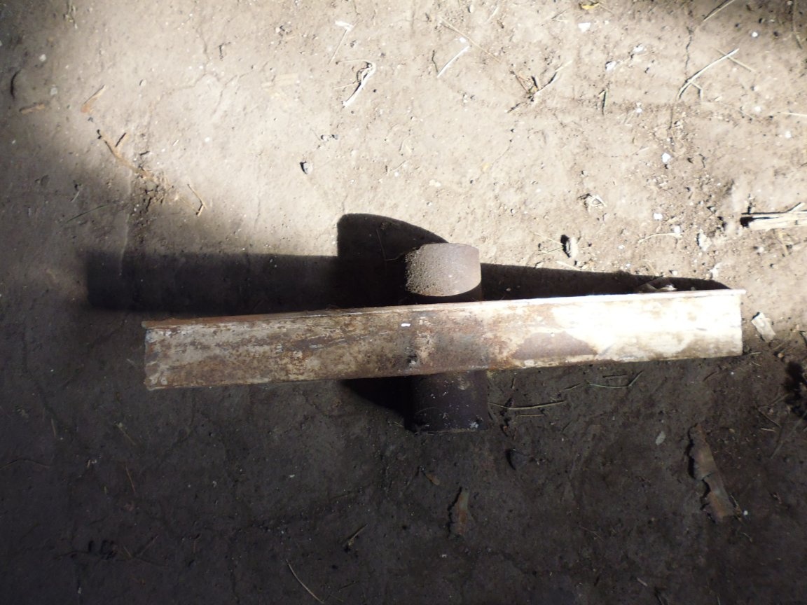
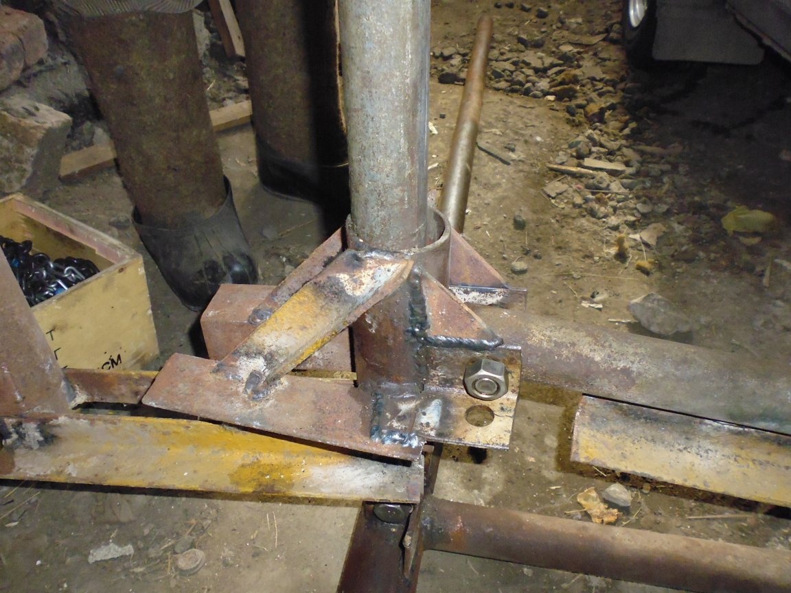
Step Ten: Assembling the Floating Support
1. The guide body of the floating support is welded perpendicular to the heel of the support, on the opposite side of the groove.
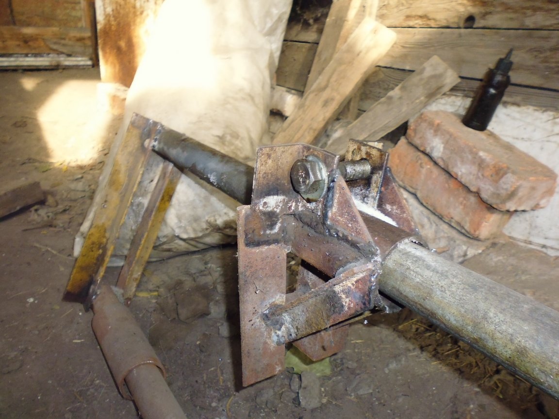
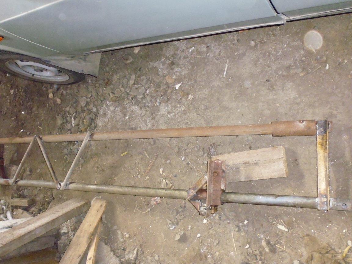
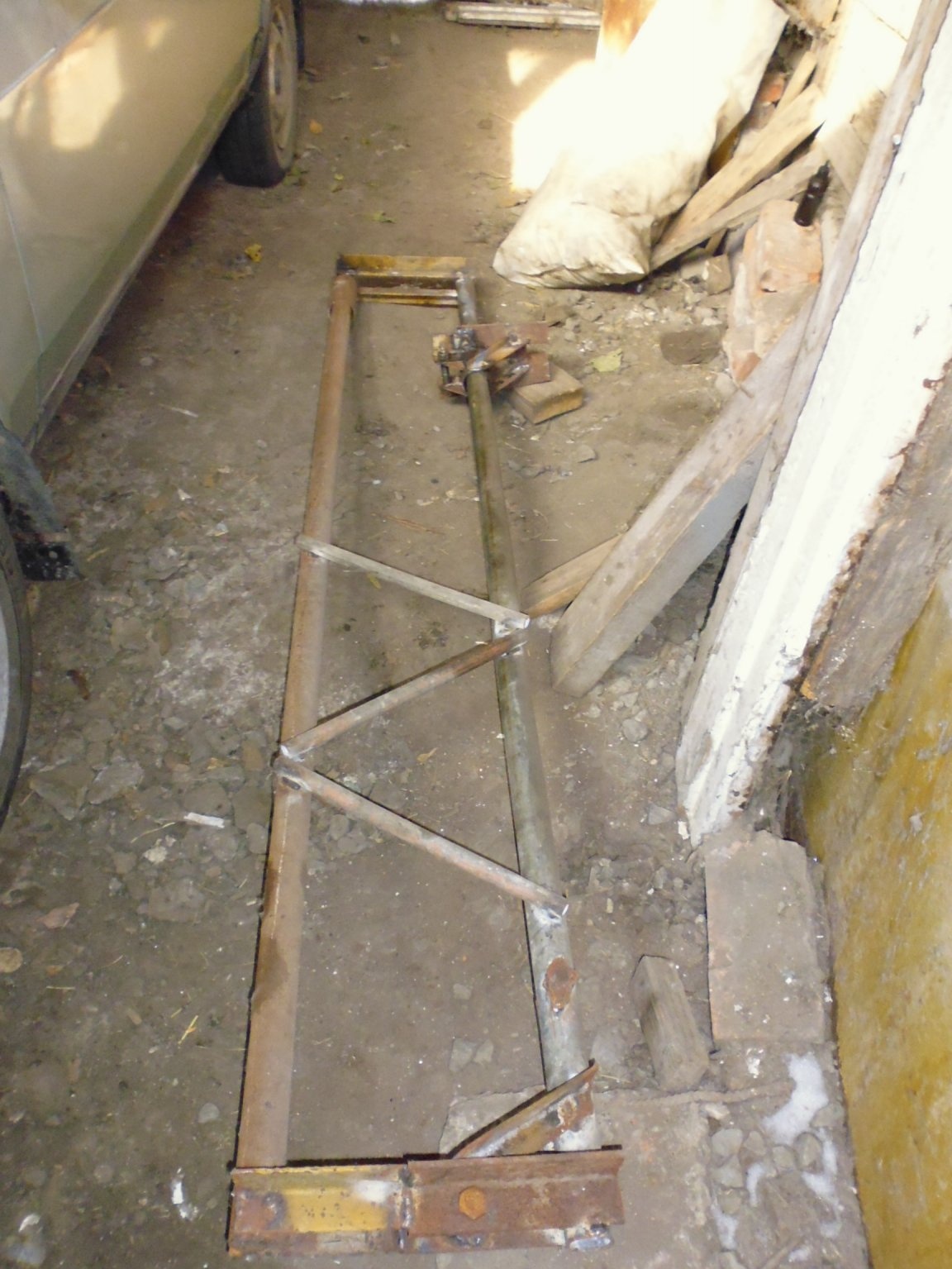
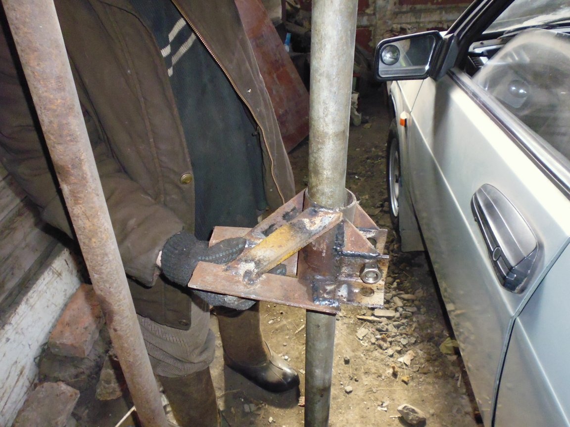
Step Eleven: Final Assembly
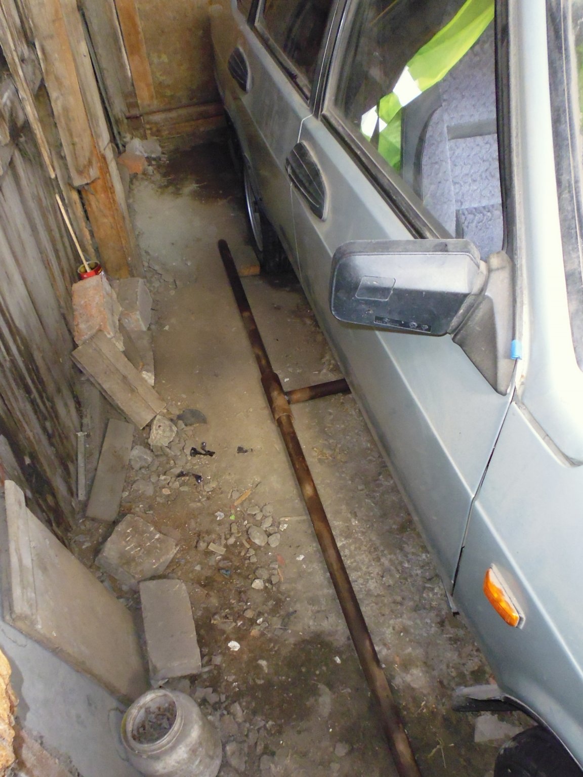
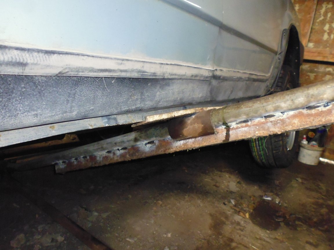
1. We lay the stop beam under the machine in the center, stepping back from the edge of the wheel 150 mm.
2. In the guides of the thrust beam, insert pipe cuts of 2-3 m.
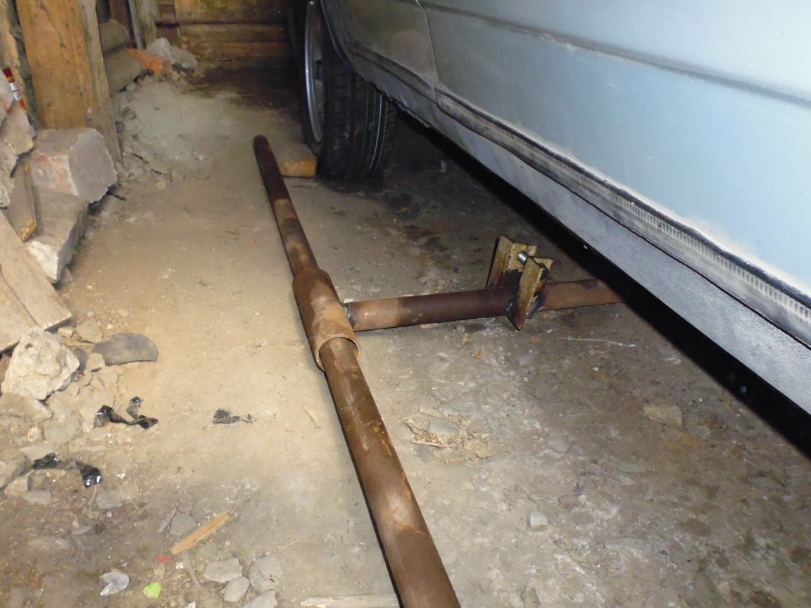

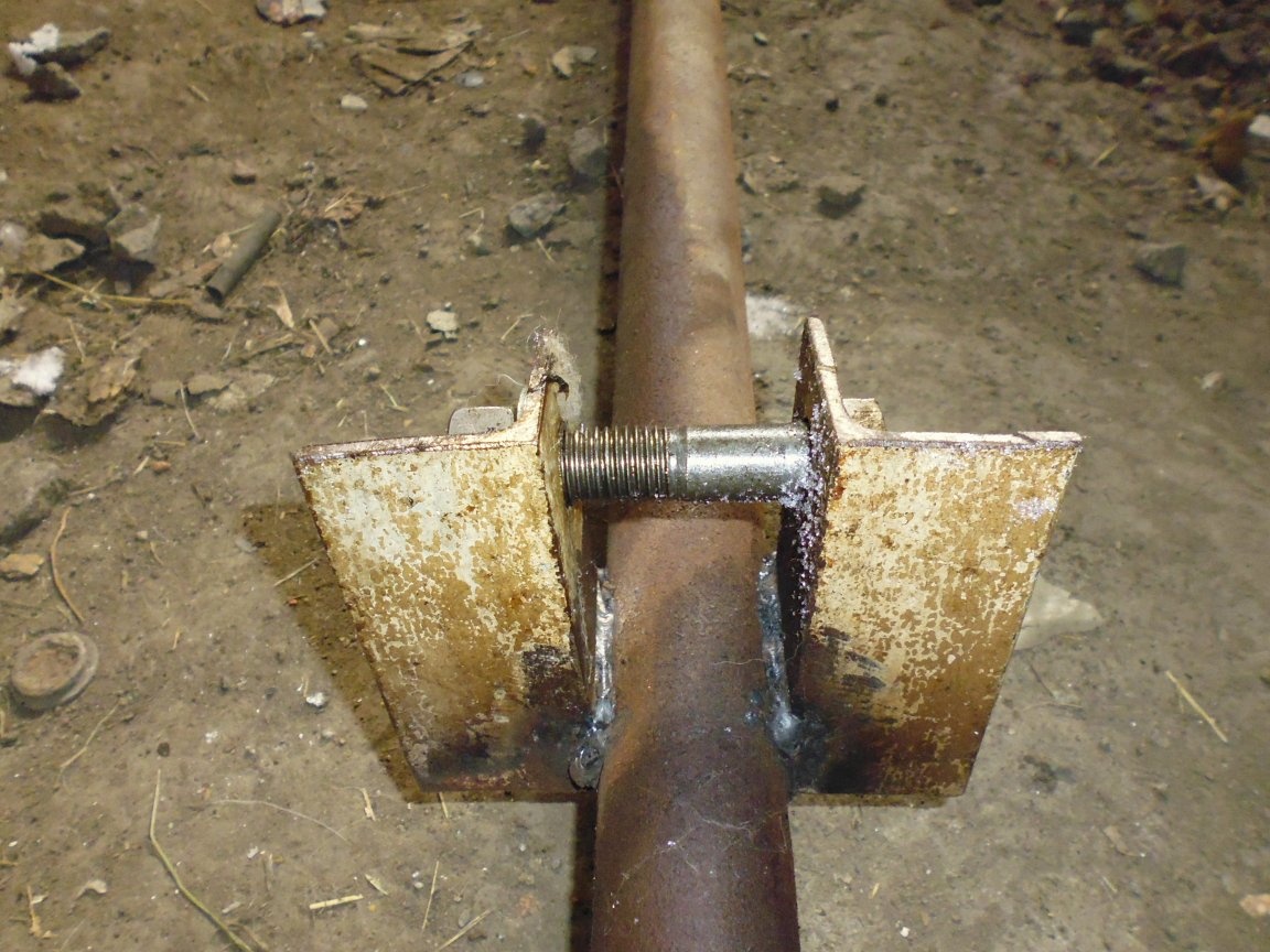
3. In the eyes of the rotary beam with a bolt and nut M16 we fasten the rotary beam.
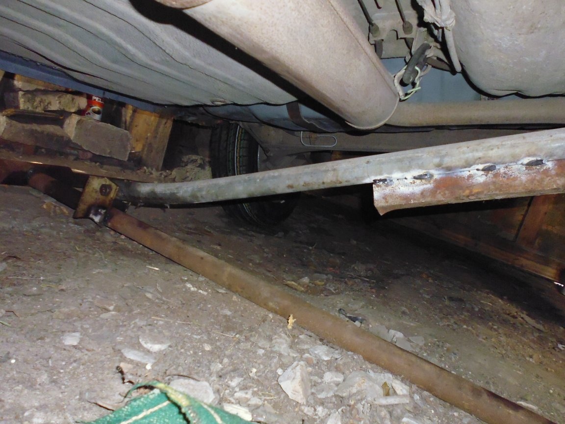
4. In the eyes of the thrust beam with a bolt and nut M16 we fix the lifting beam.
5. Install the floating support on the rotary beam with the cut edge towards the lifting beam,
pre-lubricating the swivel beam pipe with solid oil, for better glide.
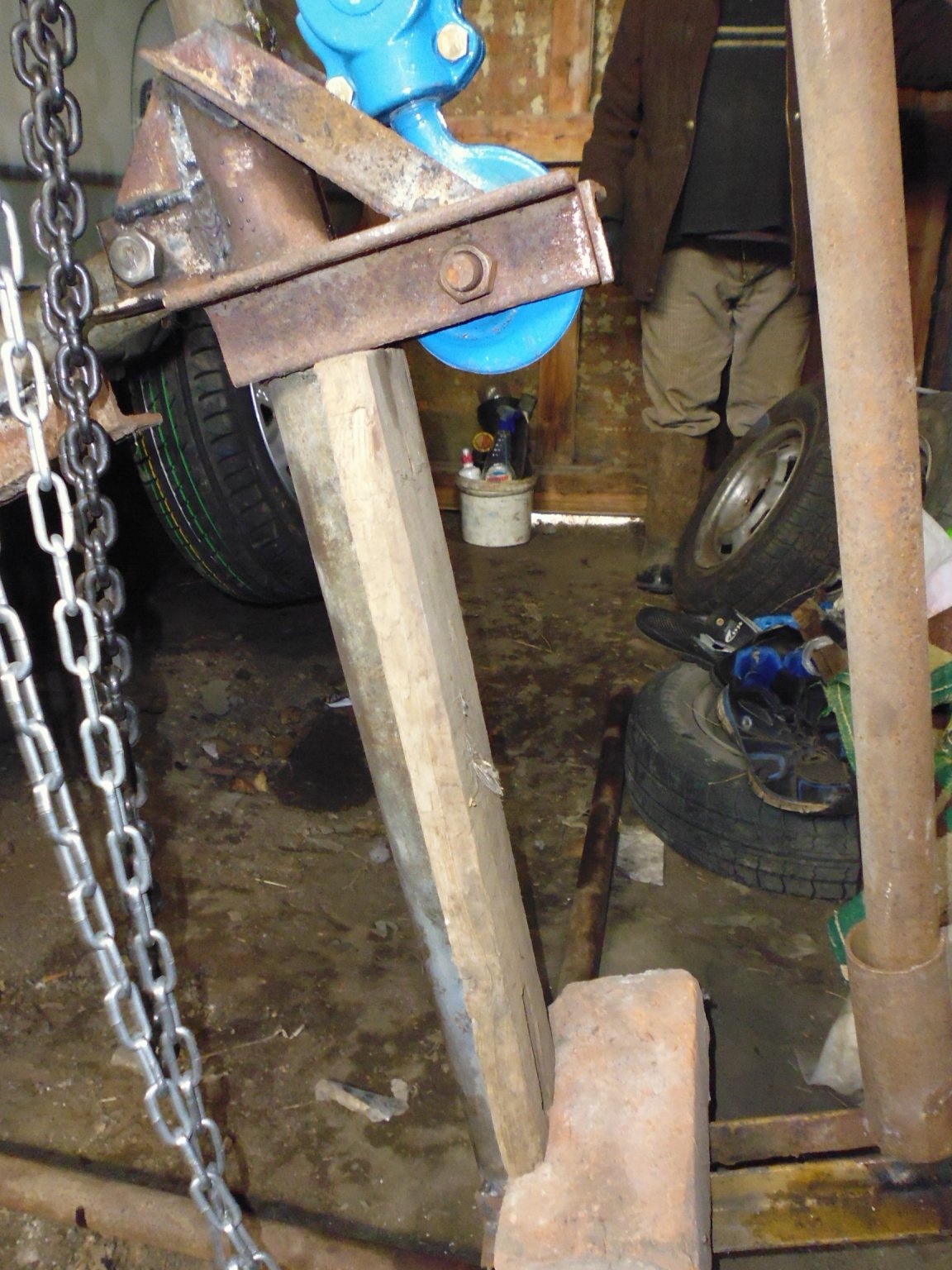
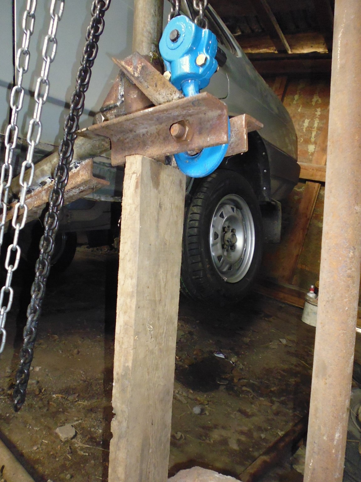
6. The free end of the rotary beam with a bolt and nut M16 we fix the lifting carriage.
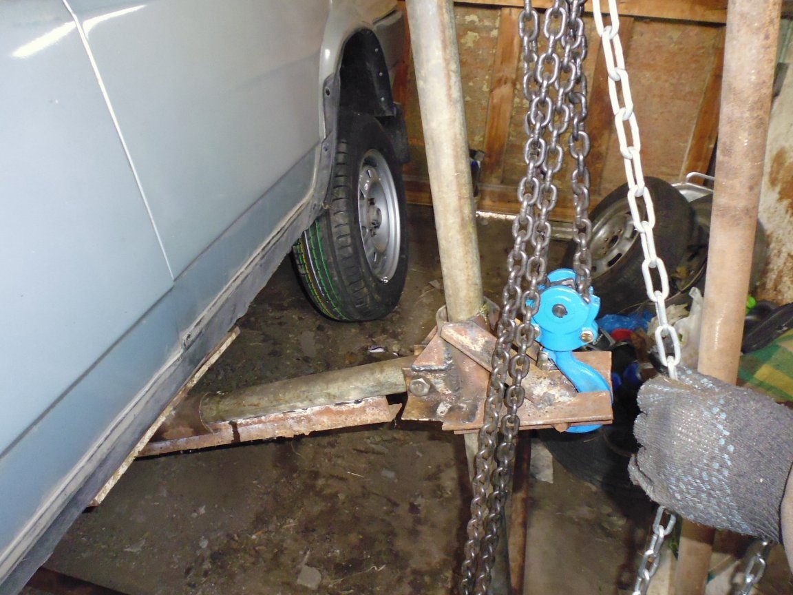
7. On the finger of the lifting beam we install the hoist, we attach the hook of the hoist chain to the finger of the lifting carriage.
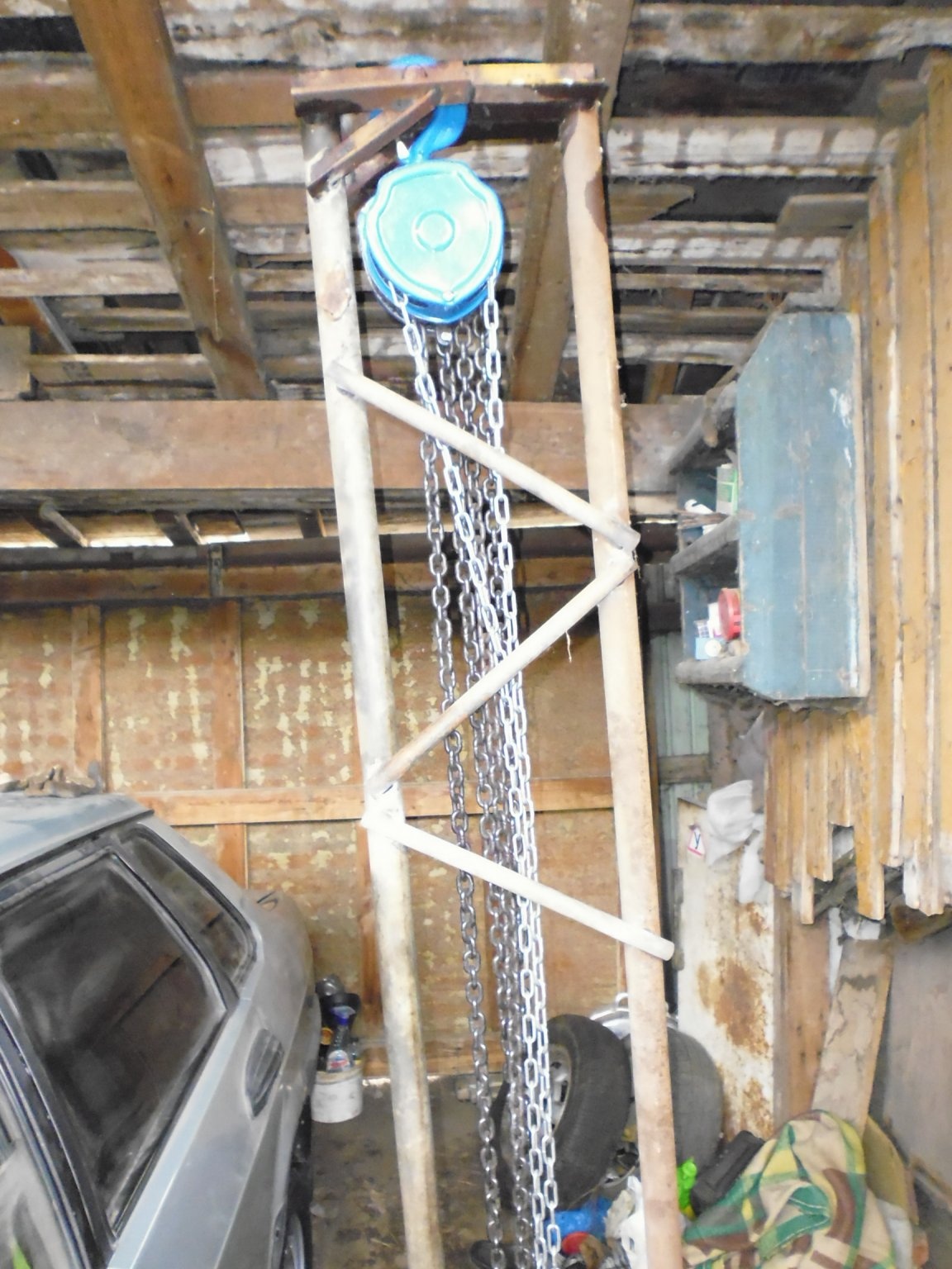
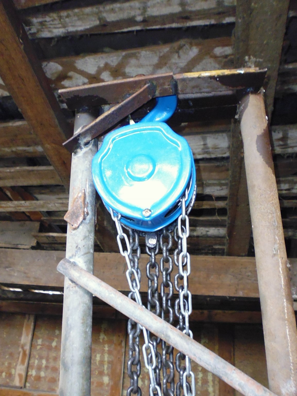
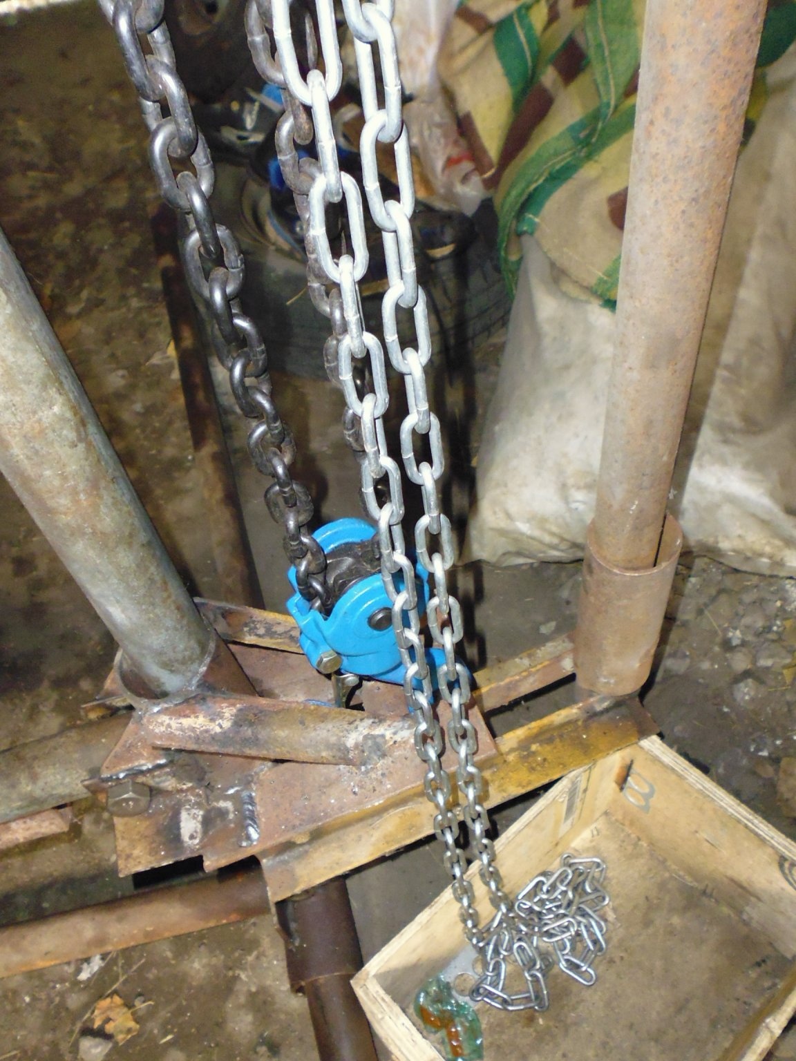
Step Twelve: Challenges
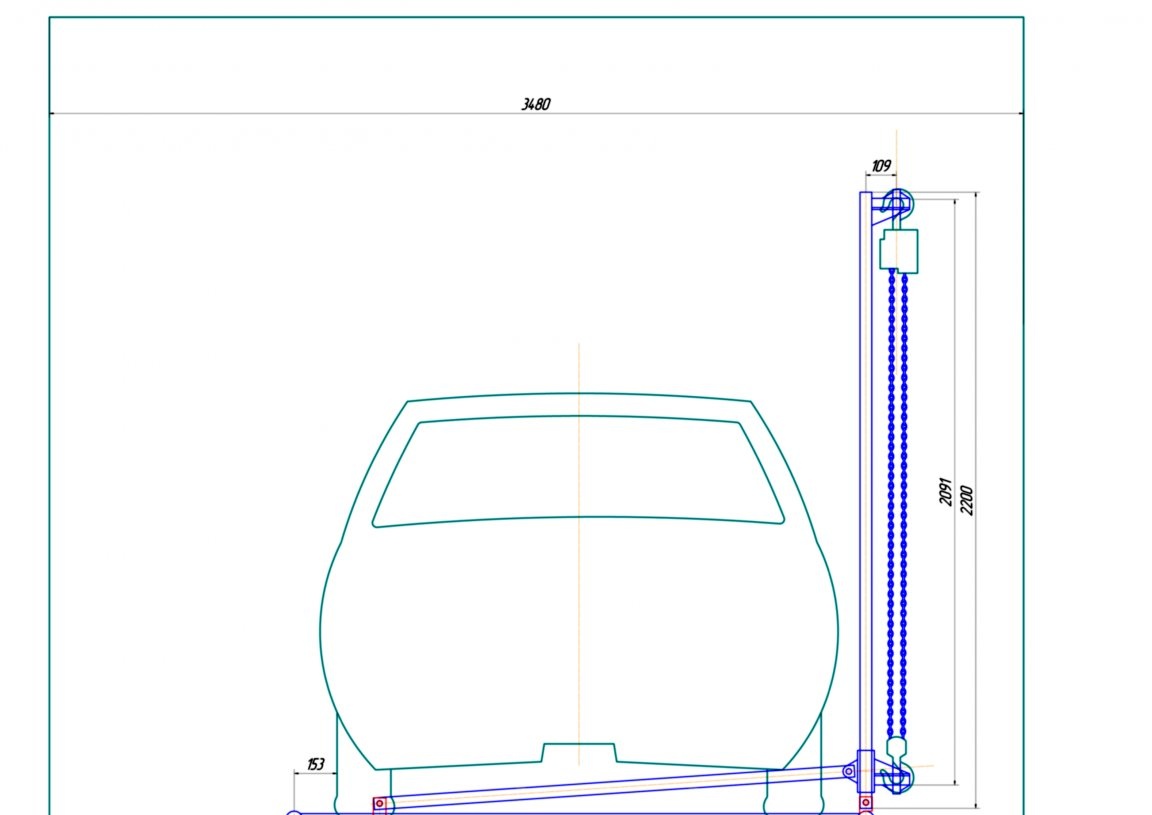
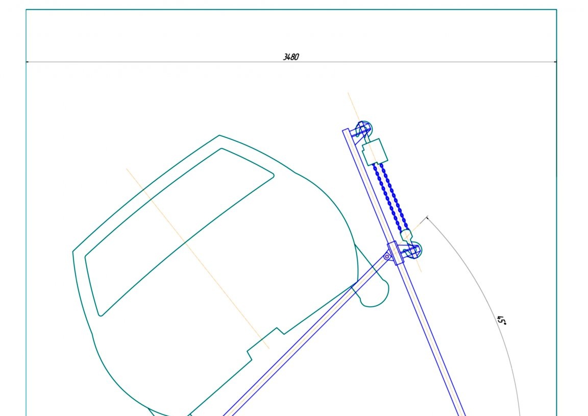
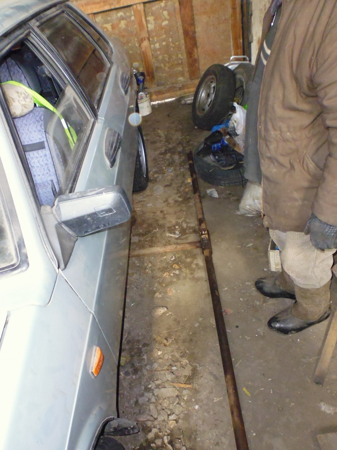
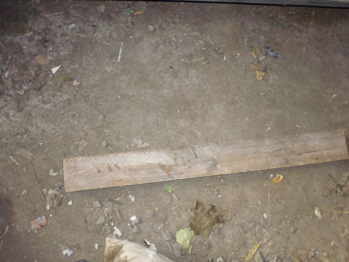
Moving the chain of the hoist, we bring the rotary beam and the heel of the stop to the lower edge of the car. One-handed rotation car to the angle necessary for repair, to fix, install a wooden beam of the desired length, between the lifting carriage and the lower beam of the lifting beam, then lower the lifting carriage slightly. The maximum angle of rotation is 45 degrees.
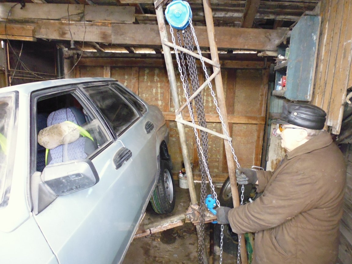
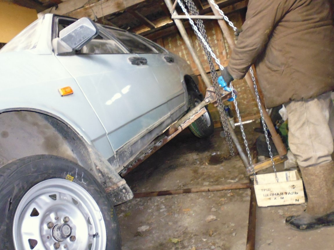
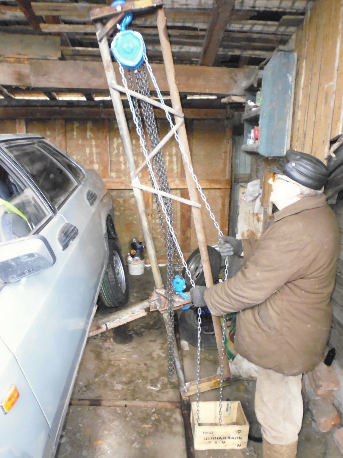
With this swivel mechanism, car repair has become much easier, even in a very narrow the garage, and now there is no need to call a bunch of people to overturn the car.