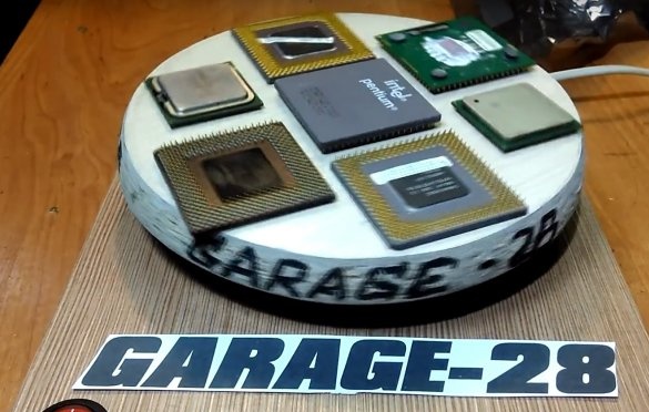
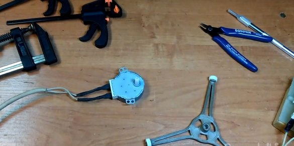
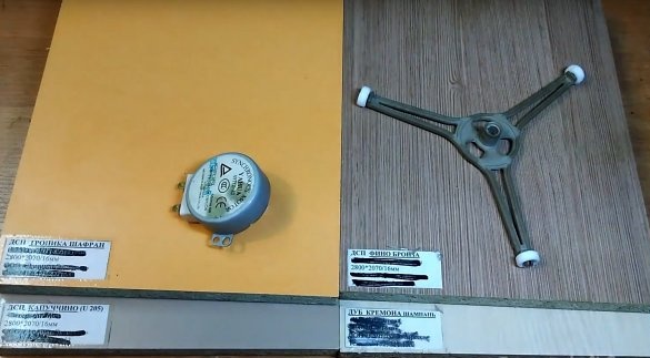
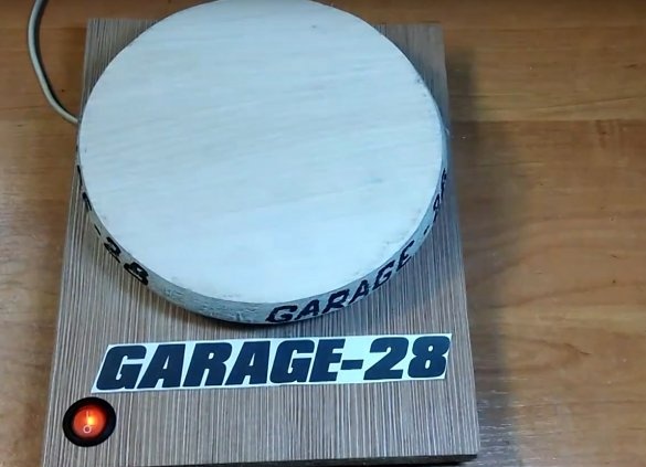
When the first microwave repair appeared, I all wanted to disassemble it into spare parts, the fan is quite quiet and low-power, while quite productive. The transformer is wonderful, and the most interesting, the engine is a twisting plate)))) I always wanted to adapt it somewhere. But the first microwave, although it was not repaired, left for the owner. The second was repaired, but it was necessary to disassemble the third to repair it))) As a result, finally we got a broken microwave oven. True, for more than a year she has lain in a pit in the garagebefore hands reached her. The first hobby was a portable fan, an article on this hobby was already on my site, and the video is also on the channel. And then his hands reached the treasured engine, which rotates the plates. Then right away everything in my head was built, what should look and work. In fact, in this article the final form is always predefined, its functionality probably implies just such a performance. There will always be a base platform for mounting the engine, and there will always be a rotating part, round, square, 8-faced, it will still be installed by the weight center on the axis of the engine.
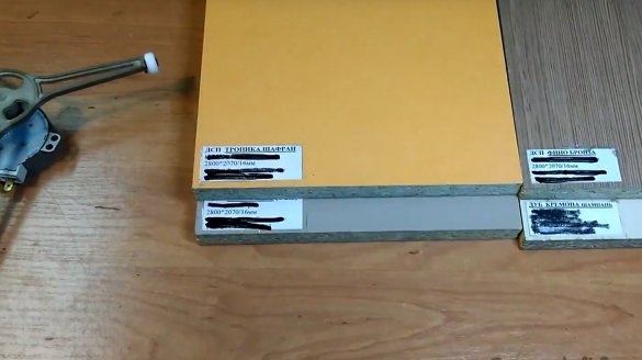
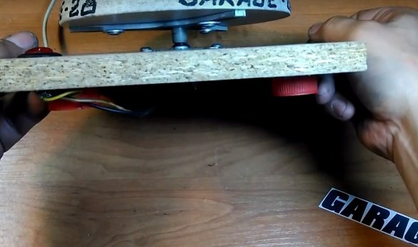
Next, there were four chipboard blanks, in different colors. Well, I chose it to mind, it was not particularly important. He marked the base in the center, calculated the shift of the upper disk, made a hole for the engine with a jigsaw. Then I cut out the upper part, screwed up a little, I don’t know how to cut circles exactly with a jigsaw, or rather I cut the circle for the first time, the canvas constantly tumbled to the side. As a result, I made such a sloping end part of the disk. Then he drilled a hole in the center for a sleeve of a 3-beam "plate stand". And installed it, pulled by screws.
I used Coca-Cola bottle caps as legs. He installed a switch in the front of the base, flooded the switch with hot-melt adhesive and closed it with a Coca-Cola lid, so as not to accidentally get under voltage. On this the first stage was completed. The video is also incidentally divided into two parts.
In the second stage, this miraclecraft got a controlled RGB LED backlight with a remote control. Here, Chinese components were already used, the LEDs decided to use normal, SMD 5050, three-segment, and not separate in color.The tape controller disassembled and secured the board without a case, under the base. IFC sensor brought out from the bottom right to make it easier to catch a signal from the control panel.
In the second stage, he also turned over the 3-beam stand and underestimated the gap between the base and the disk, even went over a little bit, so I had to put in the washers. Well, in principle, it seems like I painted all the main points, everything is shown in more detail in the videos. I hope someone else will do the same demo stands, for some reason I personally didn’t see more of such crafts, though I didn’t look for them.
Jura from the channel “as an option” generally just drilled a hole in the movable disk and stuck it on the axis without using this 3-beam stand. And I decided that it better keeps the disk on the axis, but in reality everything turned out the other way around. The axis in the well-fitting hole fits quite tightly and the slope or buildup will depend only on the straight-handedness of the author. And when using this spacer, the gap between the axis and the hole in the stand is initially and of course free play is present, and hence the rolling and tilting of the disk. So decide for yourself if you repeat this, it is better to try just to drive the axis directly into the disk first. It is never too late to increase the diameter of the hole, but it is more difficult to reduce the diameter, as in my case. Nevertheless, I did what I wanted, did it, the result personally pleased me, the project was completed. Write in the comments your opinion on this homemade, and what would be even more interesting, suggest where else could such a low-speed engine be used?

