» Electronics » Sound and Acoustics " Portable speaker. As it was before

Portable speaker. As it was before


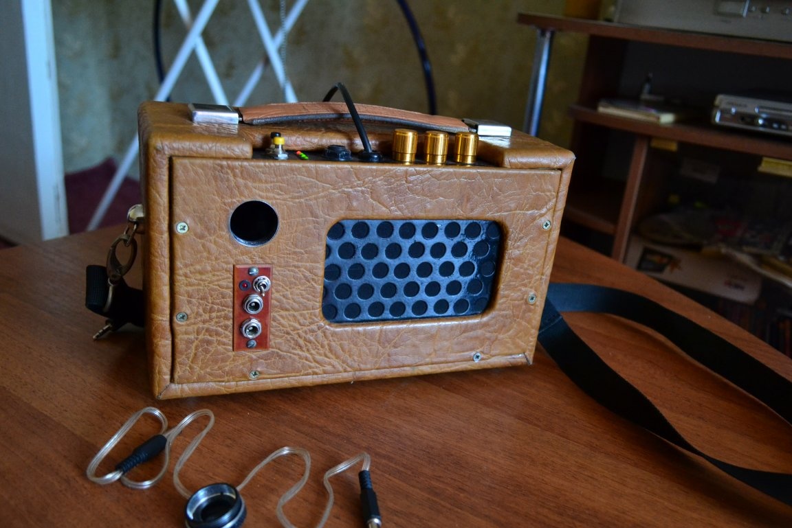
Once upon a time I had the idea to make a portable speaker for listening to music, but with the ability to connect a guitar. Yes, now it’s not uncommon to meet a teenager with screaming irresponsible music in a small box, and portable combos are easily bought through the Internet. Also, due to the spread of modular design and the availability of these same modules on aliexpress, an incredible amount of home-made products of all kinds was created. But then ... then everything was different. The presence of such a toy caused bewilderment among passers-by and delight in the company. Accordingly, with some help from friends of radio amateurs, the development of his own representative began. The goal was a portable system with the smallest possible consumption and good sound. Also, the battery should act as power so as not to spend money on batteries constantly. The result is this:


The general scheme, divided into blocks for convenience, you can observe below.


In fairness, I want to note that the column has been lost for a long time and this article is more likely a memorial in memory and a demonstration of how we did it 10-15 years ago.

ULF block


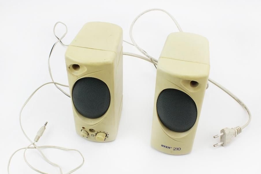
As an amplifier, the TDA2822 chip was chosen. It is noteworthy that it is better to use a chip with 16 pins, and not with 8. With the same consumption, it provides significantly better sound. The chip was designed specifically for portable systems and systems with low consumption, it is not uncommon to stumble upon it in cheap Chinese USB speakers.


A typical bridge connection. With a supply voltage of 6V and a load resistance of 4 ohms, the microcircuit is capable of delivering 0.65 watts per channel, that is, in a bridge connection we get about 1.3 watts, which is quite enough. Believe me, in the end, the unit screams in such a way that if you turn it on at full volume, then talking on a street five meters from it is not very comfortable. A big plus is the fact that the chip does not require any additional cooling, a radiator is not needed. Such amplifiers, in spite of their moral obsolescence, I collect for various projects to this day. They have good characteristics and sound definitely better than cheap Chinese D-class modules for 10 rubles.


Charging regulator, indicator.


Everything is quite simple here.The voltage taken from the emitter of the transistor VT3 is set by the Zener diode D1 and LED4. If the zener diode has a stabilization voltage of 5.7 V, then the red LED should be chosen such that the voltage sagged on it is 1.6-1.7 volts. As a result, at the output of the circuit, we should get 7.3-7.4 volts. I always set to 7.35V, strive for this value. LED3 - green. Moreover, it is desirable to use LEDs for indication, those that shine dimly and are matte. And it should be exactly green, not light green or with a yellow tint. Then this LED will indicate the end of the battery charge and at the end of its charge will glow brightly, while with a discharged battery it will dim or will not glow at all.


It is worth noting that the VT3 transistor must be installed on the radiator. I collected this charger, it is tested and working. But due to certain circumstances, later I collected and used another charger.

Portable speaker. As it was before


The description is taken from a third-party resource, I have nothing to add.

The circuit shown above is a conventional current regulator, to which a current limiter consisting of Q1, R1, and R4 is added. When the current becomes too large, the transistor Q1 opens, thereby causing a decrease in the output voltage.

The output voltage is 1.2x (P1 + R2 + R3) / R3 V. The current limit is activated when the current reaches 0.6 / R1 A. For a 6-volt battery requiring fast charging, the charge voltage is 3x2.45 = 7.35 V (3 2.45 V cells per cell). Thus, the total resistance R2 + P1 should be 585 ohms. For a 12-volt battery, the value of R2 + P1 is 1290 ohms.

In order for the circuit to work efficiently, the input voltage must be at least 3 V higher than the output voltage.

P1 is a standard trim resistor of suitable power.

The LM317 chip should be well cooled by a large heatsink.


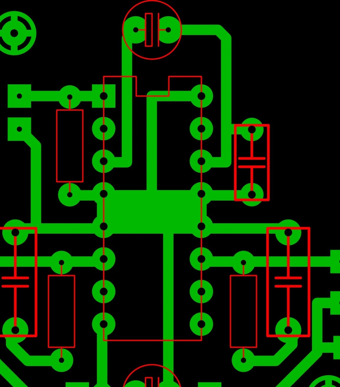
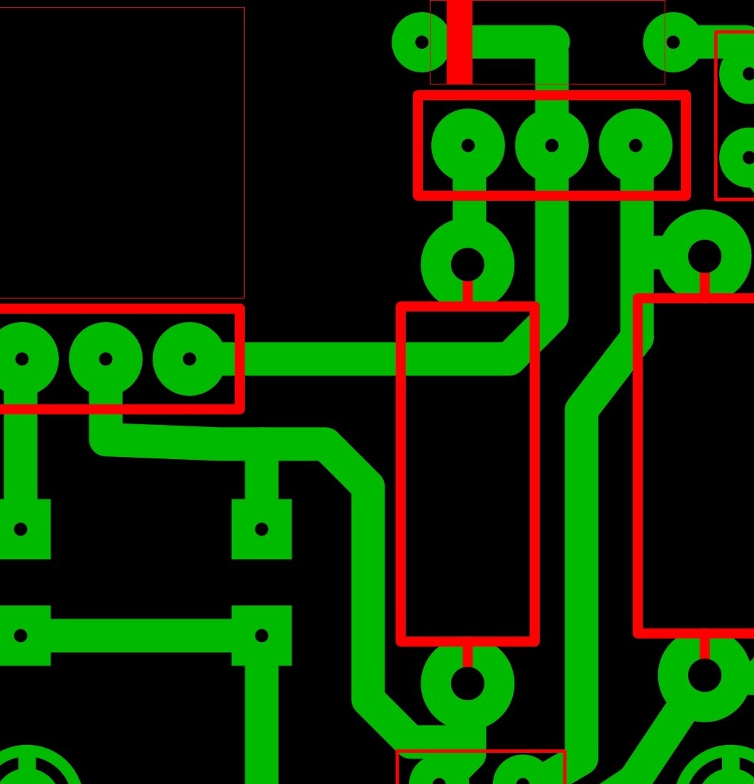
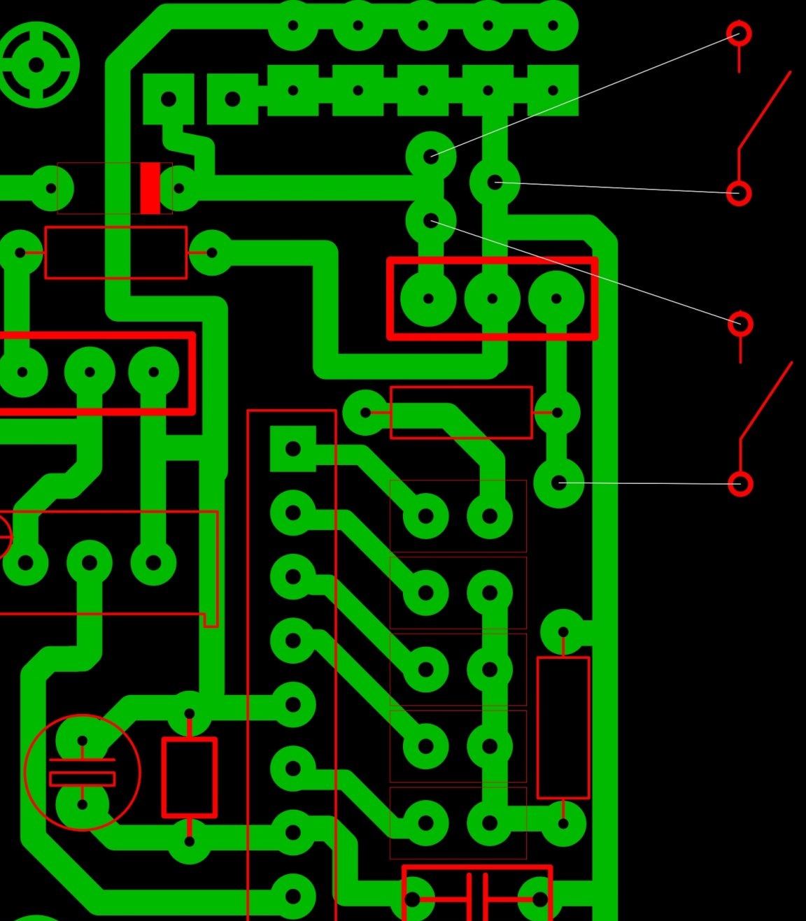
Instead of the BC140 transistor, I used 2N2222. I enclose a circuit board below, keep in mind that this circuit board is designed for the LM to lie on the textolite and a radiator will be installed on top. If you want to do as usual - just mirror the print vertically. On the back of the device there is a socket for a power supply, which can be used as any unit capable of delivering from 10.3 volts. The unit for lotions on 12V is great. But keep in mind that for charging it is better to use exactly the unit with which you tuned the stabilizer. The voltage at the output of the stabilizer, albeit not significantly, but may vary depending on the voltage supplied to its input.


Control and indication device.


This is probably the most interesting and difficult part of this device. This unit implements the ability to indicate the battery charge, as well as protecting the latter from deep discharge. The same circuit protects the device from short-circuit, you never know what rain will have to get with it. The circuit is implemented on a linear indicator AN6884 and a transistor key. You can of course just do the assembly on the comparators. Switching the device on and off is performed by the buttons SA1 and SA2. Buttons should be without locking, to short circuit. Zener diode D1 is set to "zero point", the voltage which the microcircuit will consider the lower threshold. It will have to be picked up, since it is difficult to find zener diodes with such a face value on sale. The stabilization voltage should be in the range of 5.7-5.8 volts, but not lower than 5.7V. The divider R9 / R10 allows you to further set the threshold. As it was, I used a multi-turn 1k trimmer.
Resistor R8 should be chosen so that the circuit consumption is the smallest. Transistor VT4 acts as the most common key, it can be replaced with any similar one. Better yet, use a fieldman instead, well, of course, in this case you have to adjust the circuit a bit.


Now a little nuance. 27 ohm resistors are worth increasing. Personally, I set 1.5k. Perhaps it makes sense to put a resistor on each LED separately, especially if you use LEDs in different colors.I don’t remember how I did it at home. The goal is to achieve an indication, not a glow, we are not collecting a flashlight. Our device is portable, we have nothing to spend on LEDs for. Until I increased the resistance of these resistors, this unit consumed 120 mA, almost like the amplifier itself, you see, recklessness is complete. Now only 35 mA. Strive for this value.


Overload Indication Device


Unfortunately, this part was never implemented, because the circuit needs to be configured specifically for the microcircuit, for which an oscilloscope is needed. There wasn’t one then, the idea was discarded.

Nutrition.


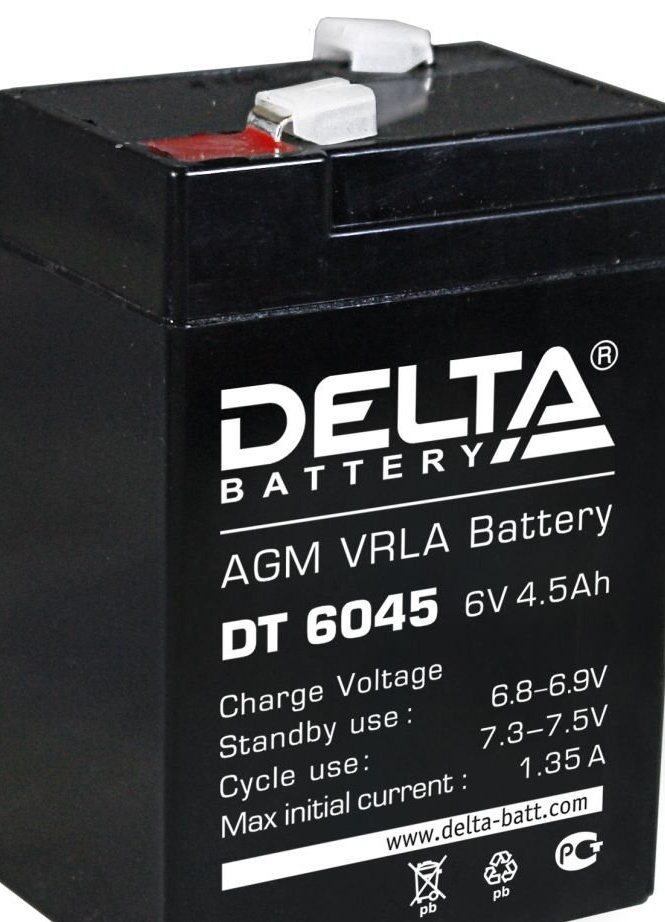
As I said at the beginning, the circuit is designed to work with a 6V lead-acid battery. It is not difficult to get these batteries on the market; they are often used in Chinese portable radio / flashlights, etc. There are different capacities, I came across 4.5 and 6 Amp hours. Better of course to take a larger capacity.


I did not calculate how long the charge of such a battery would last, but I would say that up to 40 hours was enough at medium volume. Charges all night, while you should not be afraid for it, lead batteries do not be afraid of overcharging at set charge voltage, while a deep discharge is very afraid. It is enough to bring it to the last one, as the efficiency decreases by 30%, the second time - by 50%, the third - 70%, you can throw it away. Therefore, always make sure that your battery is charged, I have already changed 2 by stupidity.


Here's how to switch blocks:


As a signal processing unit, I have the usual passive timbral block assembled according to the classical Baksandal scheme, to which I added a signal level control.


It is worth noting that the outputs from the phones / players are stereo, so the left and right channels should be connected through 1k resistors. Do the same with the connection of the guitar signal and the signal from the player, if you intend to use them simultaneously. After that, you already start the signal on the tone block. Keep in mind that such a timbral block can land a signal. On the back of the device, I added an additional power connector, to which I connect the “pizzotpyty zoom”, and play through it. You can’t imagine a better application for it.


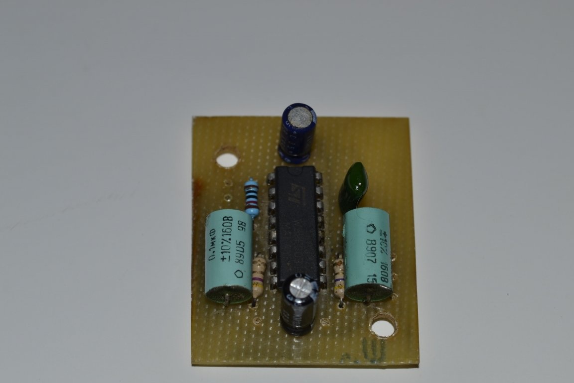
Here is one of the devices. Collected for myself. Previously, my emblem was on the grill, but then it came off. I collected more than 2 years ago, already beaten by this life) In total, about 5-6 such devices were assembled for my memory, they all work properly and delight their owners.

The case of the tenth plywood, made of the old radio Leningrad 002. There was practically nothing to do, the case of this radio itself was made of plywood boards, all that was needed was to cut them into the necessary pieces. The front wall along with the speaker are taken from there. The speaker, by the way, is very good in it (3GD-32). Some sources say that this is the best broadband speaker produced in the USSR. I cut the back cover out of fifth plywood. The grate was torn from the TV found in the forest, though I had to fight for a long time with her friend XD

And so it turned out, the case was already ready at that moment, and the grill was exactly in place, sometimes it was lucky) I pulled the handle from an old suitcase and took it to the shoemaker to sheathe leather. The case itself is glued with the so-called "vinyl skin", in general they release special material for these purposes, but in home conditions, it is replaced by the skin of a young dermantine, which is bought in fabric stores under the guise of fabric for covering the kitchen corners. There are many options, you can choose for every taste and color.


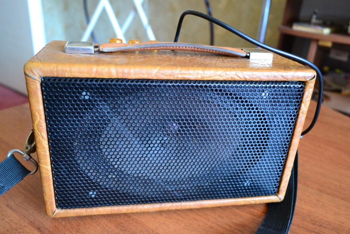
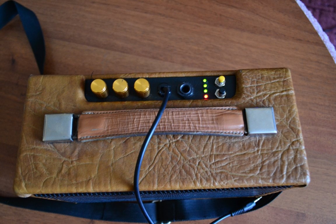
On the back wall there is a charging socket, a charging indicator, a socket for connecting external devices (in my case, a processor), a container for a processor power cord and a completely unnecessary toggle switch. He stuck the grille so that the speaker system was open, as it sounds so much better to me. The grill itself protects the insides from mechanical damage, and the fabric is pasted to protect it from dust.


Well, from above, I think everything is clear power buttons, tone block knobs. LEDs indicate battery power.


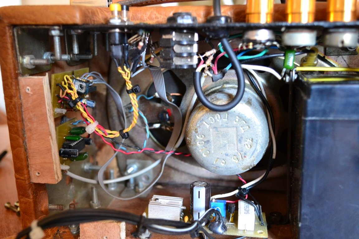
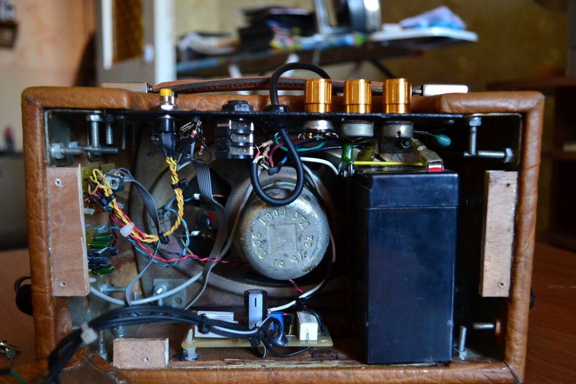
Interior. Not very neat, but considering how many times I redid it ...


Question about transportation.


If someone decides to do something like that, great advice to you. At first, when the device was just made, it was thought to carry it by the handle. But over time, it became clear how much it is not convenient. First, annoying to drag it in his hand. I generally hate carrying something in my hands. Secondly, because of the battery, the device has a fairly large weight for its size, mine weighs about 3 kg, it would seem not much, but if you walk for a long time - your hands get tired.
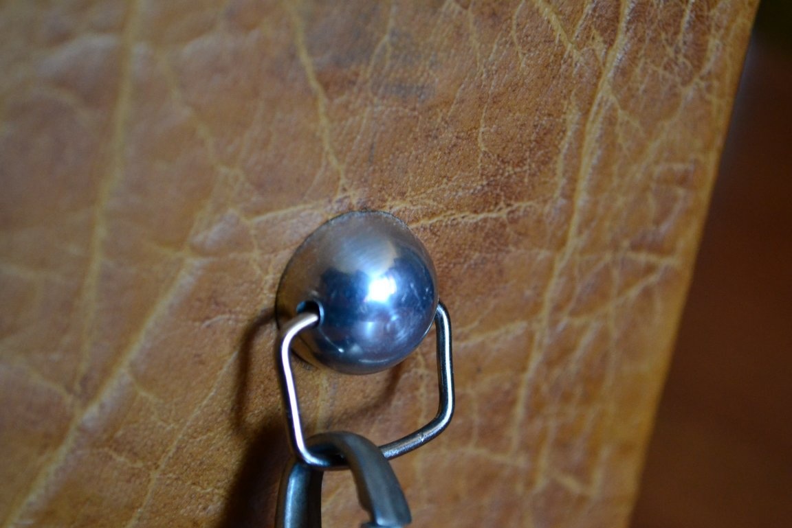
Therefore, it was decided to equip it with a belt so that it could be worn over the shoulder. The belt on the carabiners, so you can remove it if you wish. Keep this in mind when you think through the case. I just ordered two such screws with a specific hat from a turner.


In general, somehow we assembled portable speakers 10-15 years ago) Of course, now a lot of this is no longer relevant, lead has long been replaced by cheaper, lighter and more capacious Li-ion batteries, charging and discharge control modules are sold at bargain prices , and the "standard" for portable systems has become a wireless connection via A2DP. At the same time, I think the article is a good demonstration that this can also be done from the components available from the components, which can be obtained from the old (everything is relatively finite), unnecessary equipment.

Printed circuit boards, circuits, datasheets can be downloaded in one archive below.

Download
8.2
9.8
9

Add a comment

    • smilesmilesxaxaokdontknowyahoonea
      bossscratchfoolyesyes-yesaggressivesecret
      sorrydancedance2dance3pardonhelpdrinks
      stopfriendsgoodgoodgoodwhistleswoontongue
      smokeclappingcraydeclarederisivedon-t_mentiondownload
      heatirefullaugh1mdameetingmoskingnegative
      not_ipopcornpunishreadscarescaressearch
      tauntthank_youthisto_clueumnikacuteagree
      badbeeeblack_eyeblum3blushboastboredom
      censoredpleasantrysecret2threatenvictoryyusun_bespectacled
      shokrespektlolprevedwelcomekrutoyya_za
      ya_dobryihelperne_huliganne_othodifludbanclose
29 comments
Author
Quote: Korolev
mindlessly laying out absurd auto-translations,


Actually this is my article written about 10 years ago for the forum. There is no author’s symbol just because I cannot fulfill the main rule for this, to take a photo of the finished device with a piece of paper, because the column itself is no longer there.
Author
Quote: Korolev
Indicate where I got to the grammar


I'm not talking about you, I have no complaints whatsoever for you, I apologize for yesterday’s comment, I got excited.
Sheets of the text, with digging up to each typo - this is not constructive criticism
Indicate where I got to the bottom of the grammatical (not distorting the meaning of the stated) typos. And I consider the comments on the thoughtless laying out of absurd auto-translations to be constructive criticism!
I react to constructive criticism absolutely calmly
This is what yours say
Sheets of text
smile
Author
I react to constructive criticism absolutely calmly. Sheets of the text, with digging up to each typo - this is not constructive criticism, and certainly not healthy and friendly. And the negative reaction to such sheets is more than adequate, and I am not one example to this. Although I must admit, it's still my fault, as they say - do not feed the troll.
Dear Korolev, please indicate at least one sentence from my copyrighted articles where I boast
Actually, I expressed his attitude to the topic of publication of their crafts, please indicate where you have seen hints at anyone specifically! Unlike your inadequate response to healthy, friendly criticism aimed specifically at tips and tricks for those who will repeat published homemade products ...
A couple of pensioners who, instead of helping, advising, and prompting, trample everything they see with dirt, because no matter what education they have, they stayed at the level of school age and consider themselves to be the navel of the world.
scratch
Author
Quote: Ivan_Pokhmelev
You did not finish


Actually I’ve finished, but it’s not important, I’m not going to prove something to you anyway.

Once again pass the exam on the basics of electrical engineering


“Once again”, as it were, means that I have already passed it.

"I do not want"


It occurred to me in the first place. I just didn’t want to believe that an educated person would spend several hours a day on fun in the form of writing comments for a very strange purpose, to assert himself, which was worth doing 40 years ago. Seriously, look at yourself, all your comments are an attempt to show how smart you are and how stupid everyone is. Ala I D'Artagnan, and all n ****** s.

not for bragging


Dear Korolev, please indicate at least one sentence from my copyrighted articles where I boast. Thematically. I write all my articles in order to share information, I post circuits and printed circuit boards, (which, I bred myself) I bring the assembly to the level of a designer. But who cares, right? A couple of pensioners who, instead of helping, advising, and prompting, trample everything they see with dirt, because no matter what education they have, they stayed at the level of school age and consider themselves to be the navel of the world.
I'm not interested in killing time for some little money
I completely agree, I’ll add, if I’m up to something, then for myself, and not for boasting, and I will not bother with lighting, high-quality shooting, etc., which greatly interfere with my work! nea
You are a logician, for you the world of emotions and intuitive perception is beyond the bound of the conscious))
Quote: feonor12
I am not an engineer, and the wiki suggested only as an example.
Based on your text, I'm talking about
if suddenly I want to take the exam again on the basics of electrical engineering do not wait for me, I will call the teacher from the university in which I studied
I thought that you graduated from a technical university, now it becomes clear that you did not finish your studies and left the school somewhere after the third course.
Quote: feonor12
I have been using this symbol since I was eight years old, it is not new.
The fact that you have been using it since you were eight years old does not mean that you are doing it right.
Arguing.
Easy. )))
Based on the above, I can only find one justification for this - you can’t.
You didn’t even have the more obvious answer - “I don’t want to”. It is not interesting to me to kill time for the sake of some small money. I have a pretty decent pension, the garden plot makes it possible to save on the purchase of products, so I don’t see a special need for low-productivity labor. 300-400 rubles is not the amount that is worth trying. And I don’t like to do it horrible and I won’t. If he lays down and suddenly needs money, I’d better go to work in my specialty.
You confirm that with the logic you do not care: Dmitrij He gave a quote from two mutually exclusive statements, so it was not clear what his sensation refers to, if logically, then to the second. For some reason, you attributed Sharikov’s words to me.
We will calculate it by IP)))))
Author
- Yes, I do not agree.


The feelings of people from your disagreement do not change)
Author
Real engineer


I am not an engineer, and the wiki suggested only as an example. I have been using this symbol since I was eight years old, it is not new.

It doesn't matter with your logic, Evgeny Vladimirovich


Arguing.
Quote: feonor12
the symbol of repetition from this given symbol has not ceased to be.
Only in tables. The real engineer turns to Vicki last, if he could not find the answer in serious literature and standards.
Quote: feonor12
just one justification for this - you can’t. And you can’t for two reasons:

And again, your untruth. )) It doesn’t matter with your logic, Evgeny Vladimirovich. ((
- Yes, I do not agree.
- With whom? With Engels or with Kautsky?
- With both.
© "Dog Heart"
Author
Write nonsense we can


Yes, the whole article is complete nonsense

True amateur radio


I'm not real, I'm fictitious

I do not use Wikipedia, but the standards


Use whatever you want, this symbol has not ceased to be a sign of repetition.

Ivan, you are a very selective person. You cling to any little thing that you can catch on, right down to the black spot, ignoring the text that prevents you from doing this. At the same time, there is not a single article from you, an engineer. Do not bother with your standard answer that it is not for me to tell you what to do. I do not indicate, I am only stating a fact. I posted this article about 10 years ago on the forum, I was about 17 years old then. The forum died, I asked the admins to remove it from there and copied it here. So 95% of the article was written when I was 17, the remaining 5 are a little retouch. No matter how old you are, what you regularly remind everyone of, I’m sure 10 years ago you also shone, but as I said, there are no articles from you. And for them, as you know, they pay money. I’m sure a retired person will never be hurt, and given how much time you spend writing comments on this site, it's not for me to judge, but this time could be spent on something more useful, writing a useful article about it, and get a pretty penny for it. And share your experience and knowledge with the young generation at the same time. But you do not do this, and based on the above, I can only find one justification for this - you cannot. And you can’t for two reasons: either you survived several strokes, which deprived you of working capacity so much that you can only print, and in this case I sincerely sympathize with you, or, you simply do not know how.

Thanks for the constructive criticism, I could fix it - I would fix it. As you can see from the new articles (meaning those written right now) I grow as a radio amateur. Well, at the expense of the checkers - you understand me. All the best.
I’m pretty sure that you have worked as a teacher all your life

And again, your lie, I did not work as a teacher for a day, all my working life as an engineer


Yes, I also have this feeling initially
Quote: feonor12
I will not answer questions to which you know the answer in advance and ask for fun.
We can write nonsense, we don’t want to explain what we wrote. (( Clear. ((
I understand where the nonsense is written, but for those who decide to repeat your product, text inconsistency with the scheme and erroneous statements can lead to the wrong path.
Quote: feonor12
Electronics - my hobby, I need something - I found a circuit, put it together.
True amateur radio implies the desire to understand and understand what is soldered and why it works this way.
Quote: feonor12
Before me this scheme was repeated by three people, in fact, he, the author, and two more friends. Personally, I have assembled three more devices. Everything works fine for everyone. Based on this, a reasonable question is brewing for me: Have you put together a circuit and something does not work for you? Then let's get it together. Otherwise, the conversation comes out as in the joke "Do you want to ride or checkers?" It seems to me that you have checkers.
Where did I say that this will not work? Will be. Only the explanations that you gave partially did not correspond to the scheme, which you actually admitted by changing the numerical data when answering my question.
Quote: feonor12
This is a standard repetition sign, or “see above.” You can google it on wikipedia.

Your untruth, uncle. Unlike you, I do not use Wikipedia, but the standards. In fact, according to clause 4.4.16 of GOST 2.105-95, quotation marks replace repeating text only in tables, moreover, if the repeating text consists of two or more words, at the first repetition it is replaced with the words "The same", and only then with quotation marks.
You have twice broken this paragraph with your quotation marks.
Quote: feonor12
Well, tell me what it is, demonstrate that you can not only ask questions, but also answer them!
The fact of the matter is that the inclusion is mysterious and illogical, so you need to explain.
Quote: feonor12
I’m pretty sure that you have worked as a teacher all your life
And again, your lie, I did not work as a teacher for a day, all my working life as an engineer.
Author
Let's get it straight.I will not answer questions to which you know the answer in advance and ask for fun. But if I suddenly want to take the exam again on the basics of electrical engineering, don’t wait for me, I’ll call the teacher from the university in which I studied.
Answering the specifics - yes, I collected it without understanding. And why?

Firstly, I'm not an electronics engineer by training. Electronics - my hobby, I need something - I found a circuit, put it together. No need - not looking and not collecting. If you are an electronics engineer by training, I congratulate you, I have an education in another field.

Secondly, this scheme was developed by my friend and comrade, an engineer by training and working in the local central scientific laboratory, therefore I have no doubts in his competence. Before me this scheme was repeated by three people, in fact, he, the author, and two more friends. Personally, I have assembled three more devices. Everything works fine for everyone. Based on this, a reasonable question is brewing for me: Have you put together a circuit and something does not work for you? Then let's get it together. Otherwise, the conversation comes out as in the joke "Do you want to ride or checkers?" It seems to me that you have checkers.

What does this mean?


This is a standard repetition sign, or “see above.” You can google it on wikipedia.

This is not protection against short circuit.


Well, tell me what it is, demonstrate that you can not only ask questions, but also answer them! By God, based on your comments, not only addressed to me, but in general, I’m almost sure that you have worked as a teacher all your life, because when communicating with you, you have the same feelings as when passing the session.
On the red LED, according to the directory, a drop of 2 V, in fact, jumps 1.8-2.3 V, the zener diode 5.7 V, on the BE drops 0.6-0.8 V, the circuit is configured by selecting a zener diode and a red LED, so that the output of the circuit was 7.35 V.
Why, then, was to write that
Quote: feonor12
If the zener diode has a stabilization voltage of 5.7 V, then the red LED should be chosen such that the voltage sagged on it is 1.6-1.7 volts.
5.7 + 1.65 = 7.35, if you subtract 0.6, then the output will be 6.75.

I’ve found a link especially for you, you can go and protest.
Do you think that you can draw nonsense from other resources without questioning it? You didn’t give the link, but brought the text.
— // —
What does this mean?
I’ll ask the author of the scheme. Most likely protection against short circuit.
We soldered the circuit, not understanding how it works. ((This is not a protection against short circuit.
Author
Quote: Ivan_Pokhmelev
Doesn’t the BE VT3 transition fail?


Why ask a question that you know the answer to? On the red LED, according to the directory, a drop of 2 V, in fact, 1.8-2.3 V jumps, the zener diode 5.7 V, on the BE drops 0.6-0.8 V, the circuit is configured by selecting a zener diode and a red LED, that would be 7.35 V.

This is a common voltage regulator.


Description taken from a third-party resource


I’ve found a link especially for you, can go and protest.


It is much more reasonable to accept the value of the reference voltage of 1.25 V, and not 1.2 V.


— // —

VT5


I’ll ask the author of the scheme. Most likely protection against short circuit.

C9


You can not bet.
with emitter transistor
From the emitter.
voltage sagging on it
Falling Drawdown and fall are different concepts.
at the output of the circuit, we should get 7.3-7.4 volts.
Doesn’t the BE VT3 transition fail?
it’s a regular current regulator,
This is a regular stabilizer. voltage.
The output voltage is 1.2x (P1 + R2 + R3) / R3 V.
It is much more reasonable to accept the value of the reference voltage of 1.25 V, and not 1.2 V.
multi-turn trimmer
Multi-turn.
According to the control and display device. The meaning of VT5 and C9 is unclear.
So yesterday May 1!
I would say Easter, smoothly flowing on May 1! smile
Author
So yesterday May 1! Hence, there are such mistakes!)
flashed the second LED

Where did you go? Spring came chtoli?
Author
Initially, when the first charging circuit was assembled, the toggle switch was not there, but the second LED flashed. It looked pretty concise.When I assembled the second charge circuit, the second LED fell off, instead of it I put the toggle switch, which I came up with some purpose, but in the end I did not realize it. So he stood) And about furniture stubs I didn’t even know then
The socket (with the "unnecessary toggle switch") would also be deepened a little, and the heads of the screws should be closed with plugs (furniture) in the color of the case
Author
Thanks. In fact, as practice has shown, in nature he used a combo literally a couple of times. In nature, the atmosphere is not the same, I want acoustics. In the best case, quietly play along with the solyachek. So he doesn’t need a microphone at all. At the same time, no one bothers to assemble a simple preamplifier on a high-quality opamp and mix the signal through a resistor to the general one, but then you will have to add at least a volume control to the microphone, and control a guitar with a voice with one timbral unit ... and all this on the combo 1.3 Watts))) Not the tasks he has.
Guest Victor
Well, well done. For a guitar, a very nice thing in nature. Still a microphone input ...

We advise you to read:

Hand it for the smartphone ...