

This article discusses how you can make a tuner for an electric guitar using Arduino! The author was prompted to create this device by experimenting with the possibility of processing an arduino audio signal and determining the frequency. In this case, the Amanda Gassei code was used, which allows determining the frequency using Arduino. As an indication, LEDs of different colors are used, which indicate whether the reproduced string is tuned. The device works like any other guitar tuner, but you can do it yourself!
Step 1. Necessary
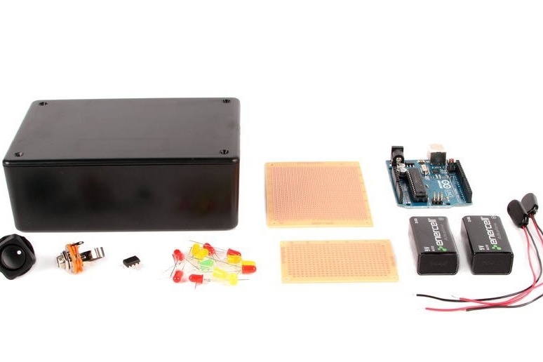
(x1) Arduino Uno (you can use Nano)
(x1) TL082 Paired Operational Amplifier TL082 (TL072, TL062)
(x1) Case 6x4x2 inches (or any suitable)
(x6) 5 mm yellow LED
(x6) Red LED 5 mm
(x1) 5mm green LED
(x13) 150 ohm resistor
(x2) Battery 9 V ("Krona")
(x2) Battery Connectors
(x1) Power connector 5.5 x 2.1 mm male
(x1) Power switch
(x1) Monaural Jack Jack 6.3 mm (Jack 1/4 ")
(x2) Development board
(x3) Resistor 100 kOhm
(x1) Resistor 22 kOhm
(x1) Electrolytic Capacitor 10 uF
(x1) Capacitor 100 nF
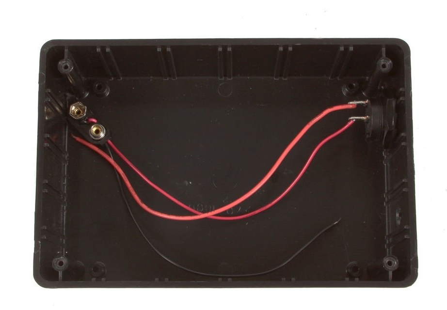
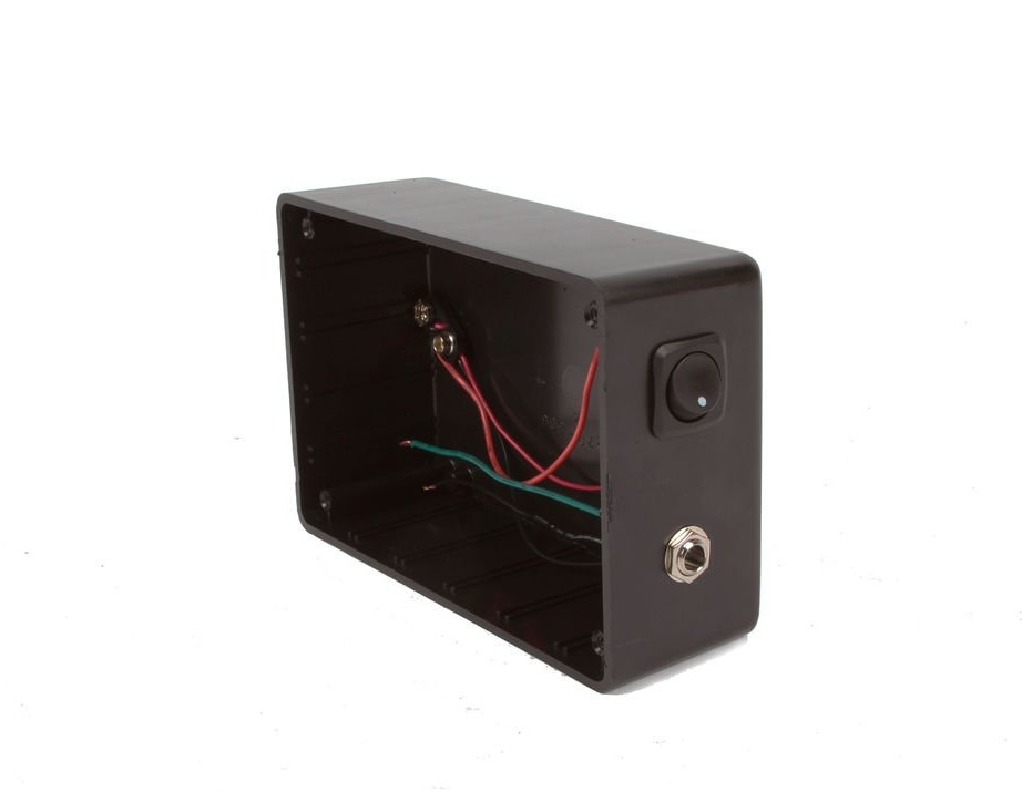
Step 2: preparing the enclosure
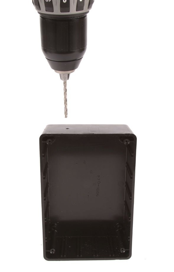
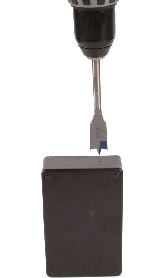

Drill all the required holes. The diameter of the holes is selected based on their specific components.
Step 3: Turn On / Off
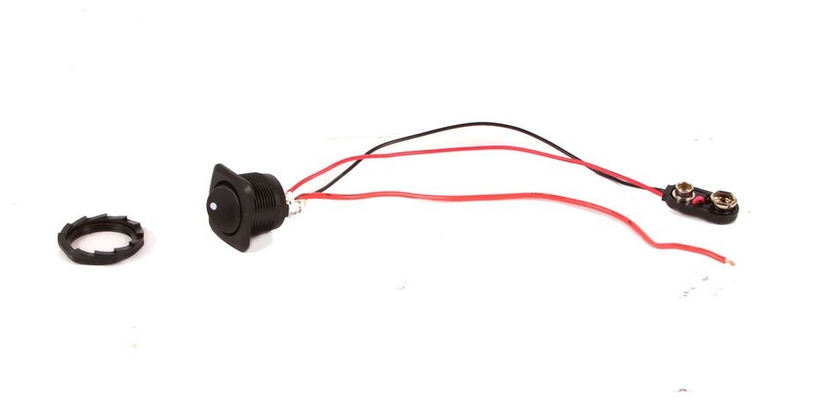
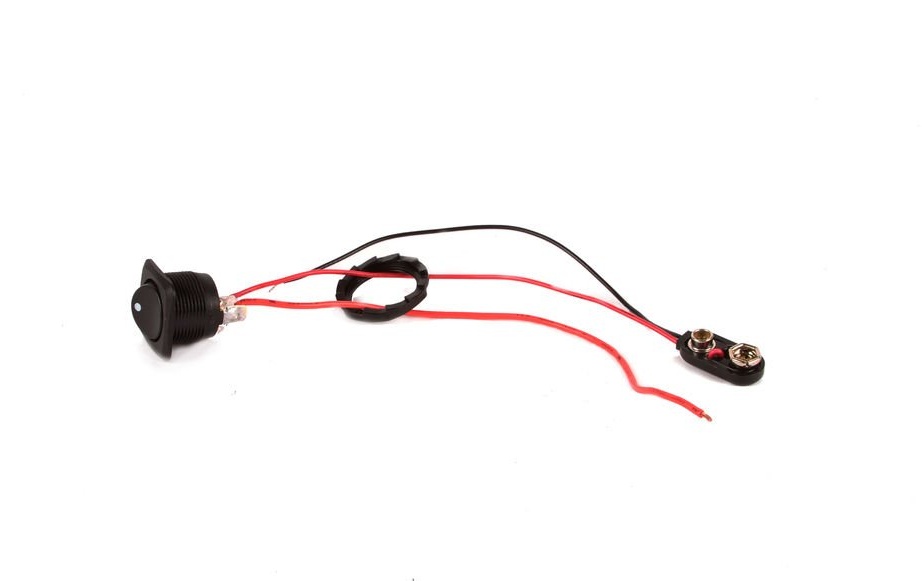

The switch must be soldered into the power gap. In this case, the author breaks the circuit from the positive contact of the battery. From myself, I can add that you can use special guitar connectors that allow you to turn on / off the power by connecting a guitar plug, in all guitar effects this is implemented in this way. In this case, the gap must be minus.
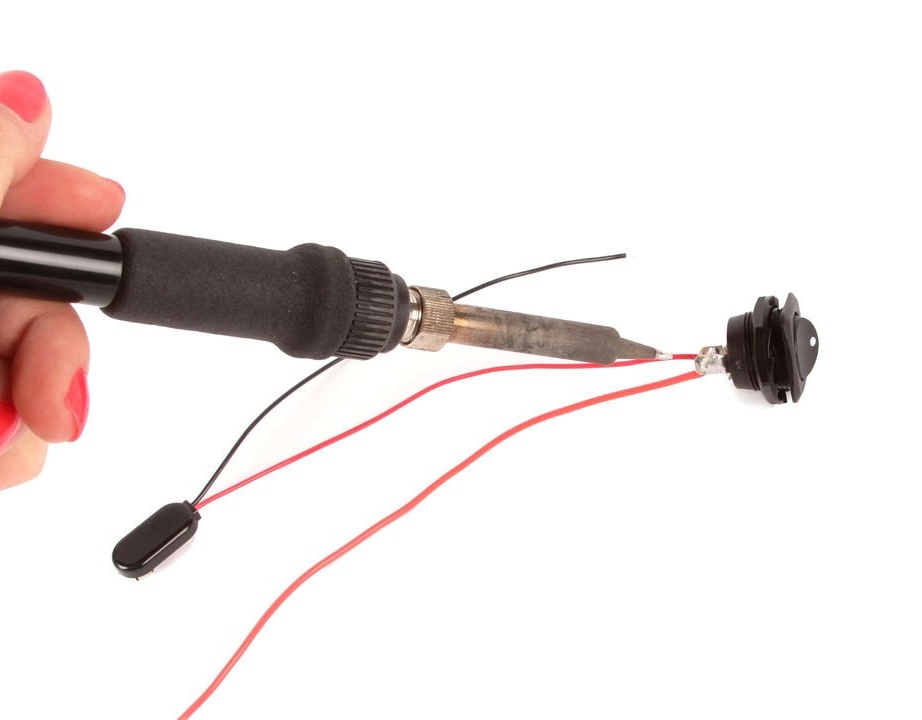
Step 4: Audio Jack
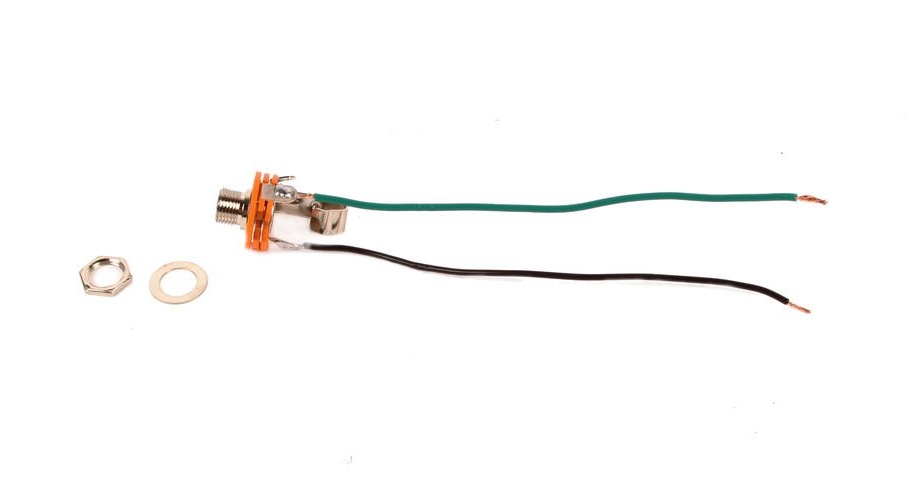
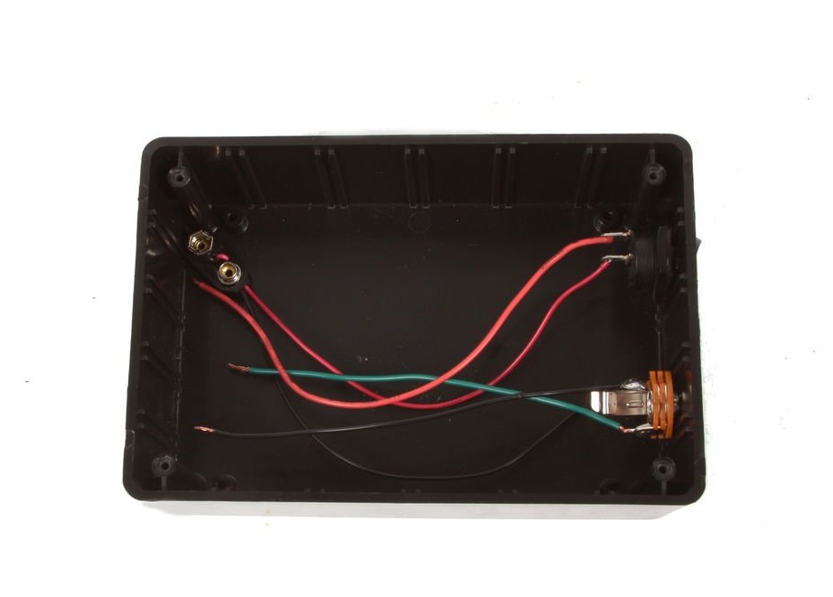
In order not to get confused with further installation, solder wires of different colors to the connector, green - signal, black - ground. By the way, the author used just such a connector, which I wrote about above, but, obviously, did not know about such functionality of these connectors.
After that, both connectors can be mounted in the housing using the supplied nuts and washers.
After that, both connectors can be mounted in the housing using the supplied nuts and washers.
Step 5: Plug
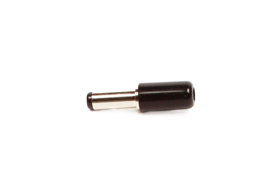
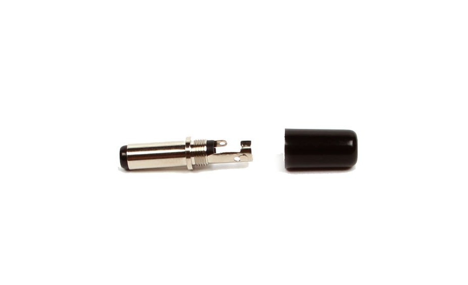
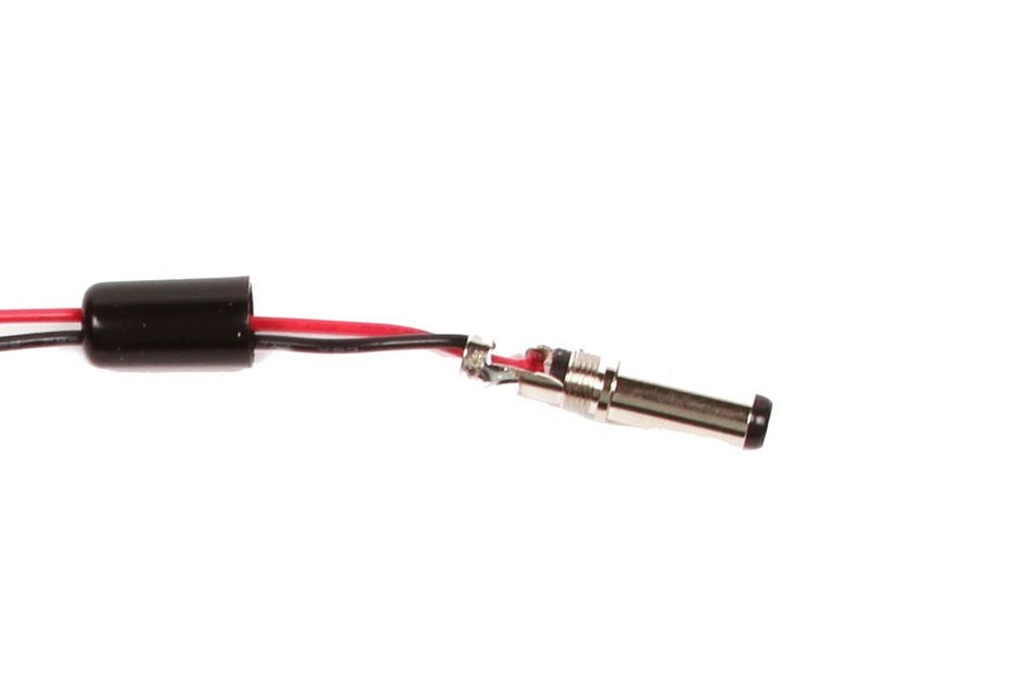
Unscrew the fork. The positive wire must be soldered to the central pin of the plug, and the negative to the external (minus "outside", plus "inside", if you look at the plug itself). Then reassemble the plug.
Step 6: Amplification and Bias
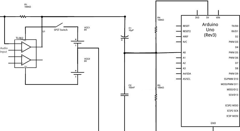
The audio signal coming from the electric guitar must be amplified to about 5 V from peak to peak, and the offset should be 2.5 volts, not 0 volts.That is, the lower peak should be 0 volts, the upper - 5 volts. This is necessary so that Arduino could read the supplied audio signal. Above, you can see the circuit diagram, which, before final assembly, it is desirable to assemble on a careless breadboard.
After that, you can send a signal to the arduino, fill in the sketch on it and make sure that everything works correctly. The required code is below (the code is hidden by a spoiler).

The port monitor will output the frequency of the played strings. Guitar strings, with standard tuning, have these frequencies:
- Sixth Mi String - 82.4 Hz
- Fifth String A - 110 Hz
- Fourth Re - 146.8 Hz
- Third Salt - 196 Hz
- Second C - 246.9 Hz
- First Mi - 329.6 Hz
At the first attempts, problems may arise in determining the frequencies of either the upper or lower strings. Amanda's code has an ampThreshold value. Changing this value, it is necessary to achieve good detection of the frequency of all strings, this value should be in the range from 10 to 30, but you can experiment with other values.
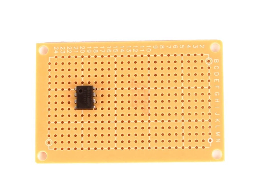
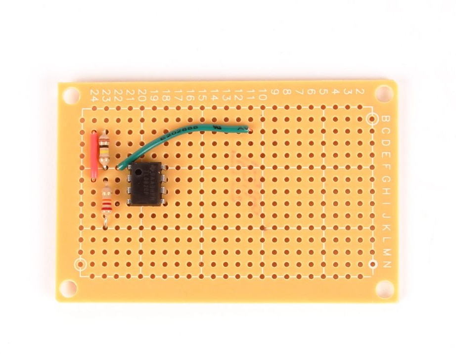
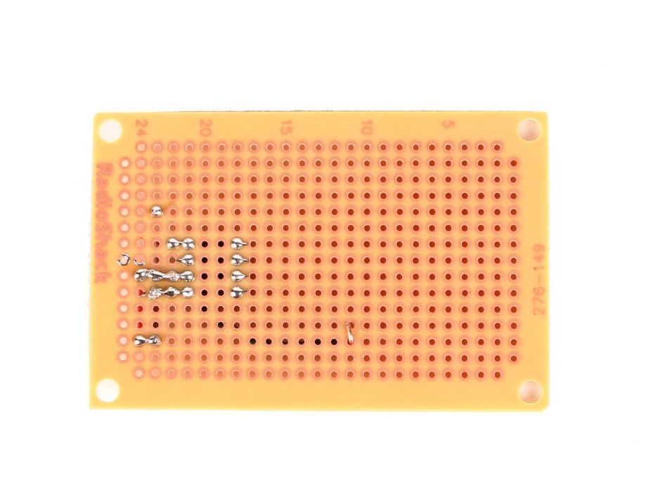
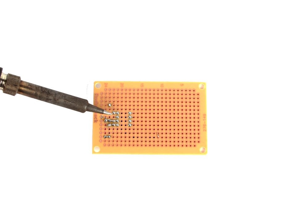
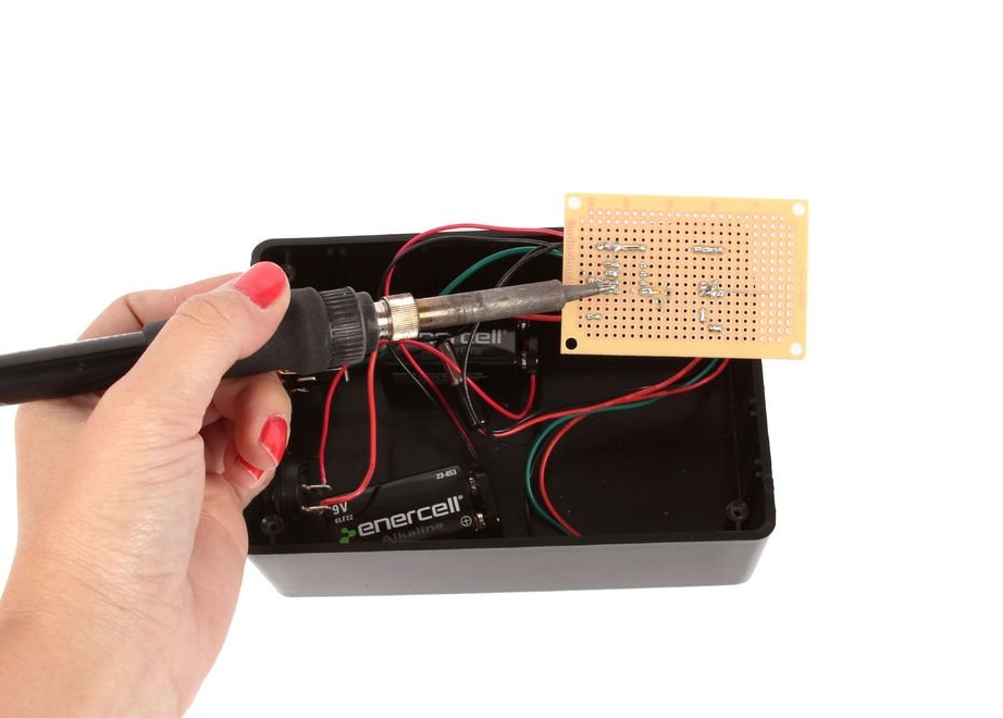
Step 7: solder the chip
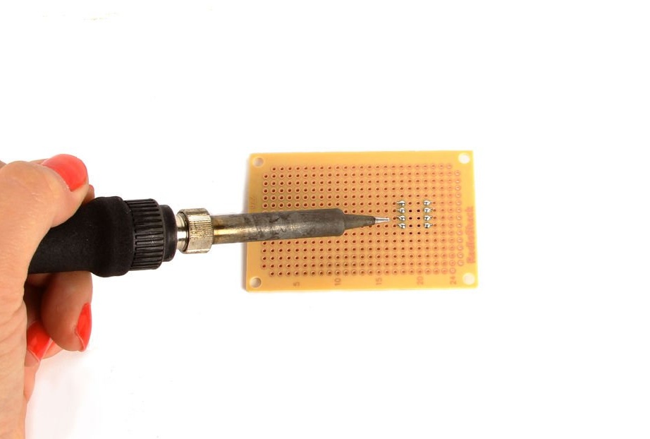
Step 8: Solder the remaining components
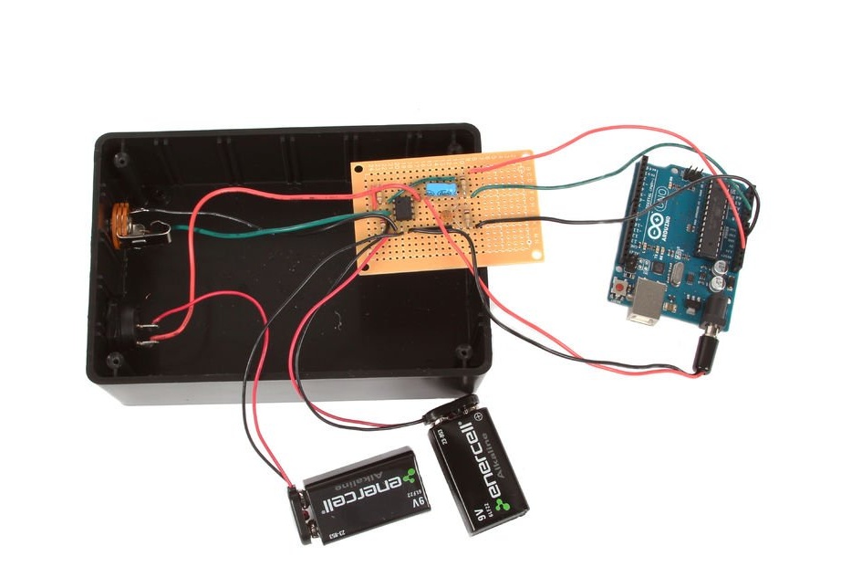
Step 9: Pre-Build
Step 10: Programming
Download the following code in Arduino.
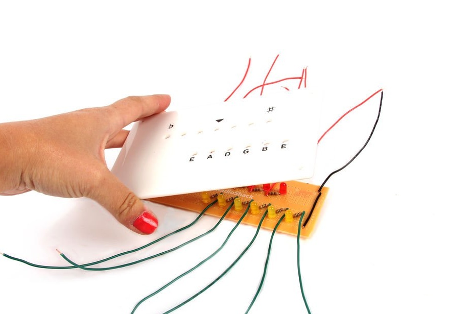
Step 11: Nameplate
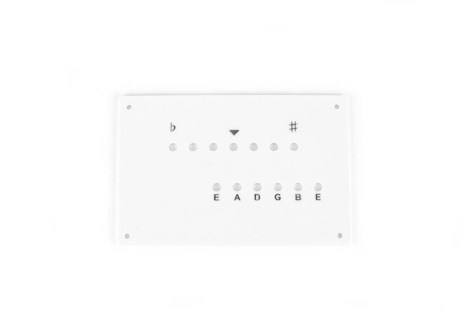
For his guitar tuner, the author chose laser cutting. Instead, you can use the standard housing cover by pre-drilling holes in it.
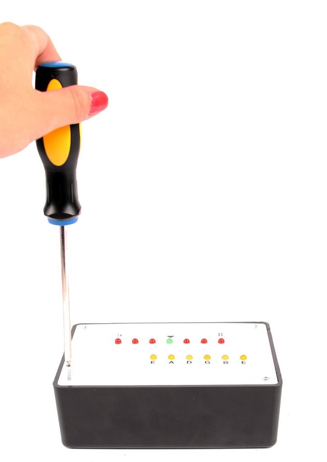
Step 12: LEDs
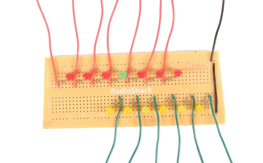
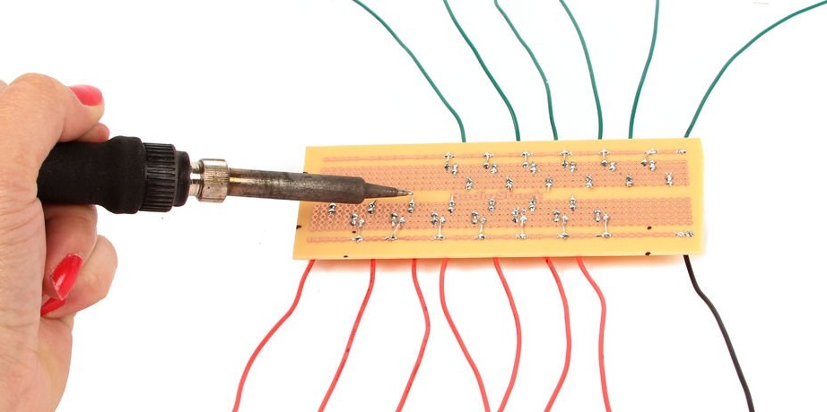
Solder the LED on the board. To do this coaxially with the holes, insert them together with the board into the cover without soldering, and then solder them. To the anode of each LED it is necessary to solder a resistance of 150 Ohms, to it in turn is a wire that will go to one of the Arduino inputs. The author used red diodes to indicate the tuning of the string, green to indicate that the string is tuned and yellow to indicate which string is currently tuned. The cathodes are connected together, and by wire connected to the earth of the arduino.
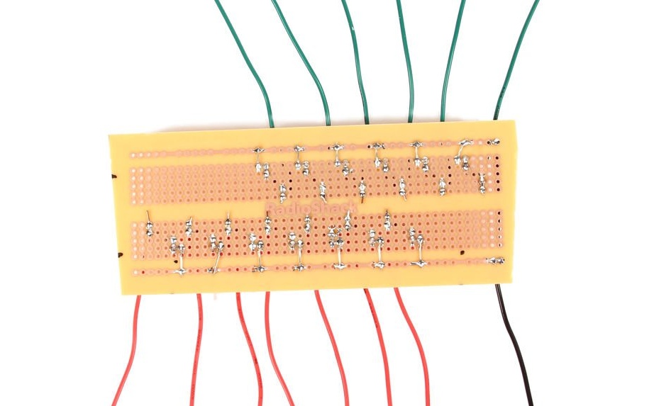
Step 13: Connecting the LEDs
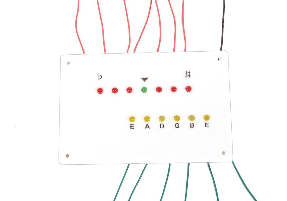
Connect the wires to the Arduino board. The following list indicates which LED should be connected to which pin.
Leftmost red LED - pin 8,
The next red LED on the right is pin 9,
The next red LED on the right is A5
Green LED - A4
The first red LED to the right of the green LED is A3
The next red LED on the right is A2
The rightmost red LED is A1
The leftmost LED with the inscription "E" - pin 2,
String A LED - pin 3,
String LED “D” - pin 4,
G string LED - pin 5,
String LED "B" - pin 6,
Extreme right LED labeled "E" - pin 7
After connecting all the LEDs, turn on the device and make sure that the LEDs correctly display the played strings and the tuning process.
Step 14: final assembly
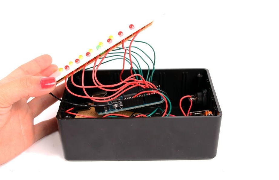
Carefully assemble the device, making sure that not one of the wires is disconnected from the arduino.
Step 15: Tune In!