It is proposed to consider the option of transferring electric shavers from battery to mains power.
And the reason for this was as follows. A light and compact rechargeable electric shaver with a Japanese design was presented for the next birthday, which was unprecedented at the time (as the inscription on the razor says).
At first, the razor pleased with its work, especially in comparison with traditional network electric shavers. But happiness did not last long. Several months passed and problems arose. The razor required a round-the-clock charge (turned off, shaved, and again into the network), otherwise there was not enough charge for the next shave. Then the battery capacity started to fall rapidly and it became pointless to use an electric razor. So she moved to the far shelf, crowded out by more modern and reliable designs, where she lay for several years without use.
Recently, in the summer season, a spare electric shaver was needed, and I again stumbled upon a deferred razor. Since her resource was not used (she worked a little, an installed knife and a mesh are working, there are spare knives), I decided to restore the razor to work.
Analysis of the causes of the defect
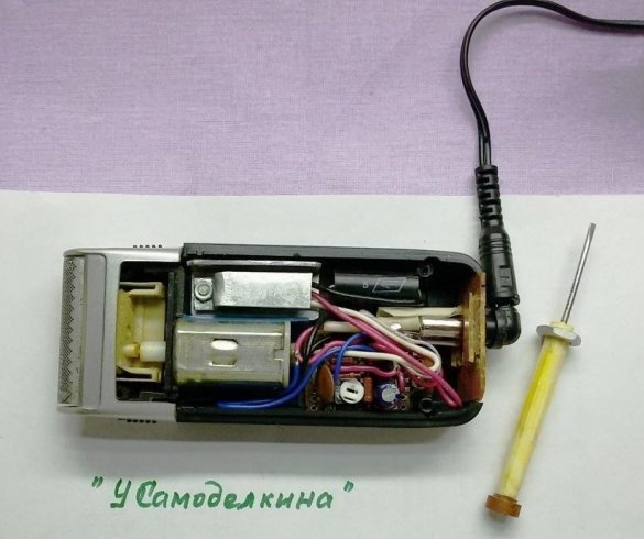
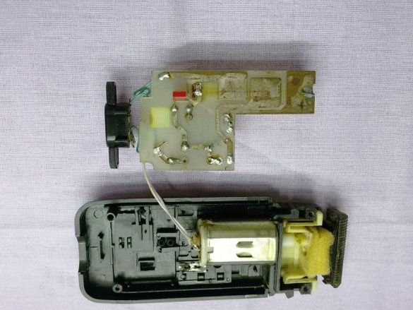
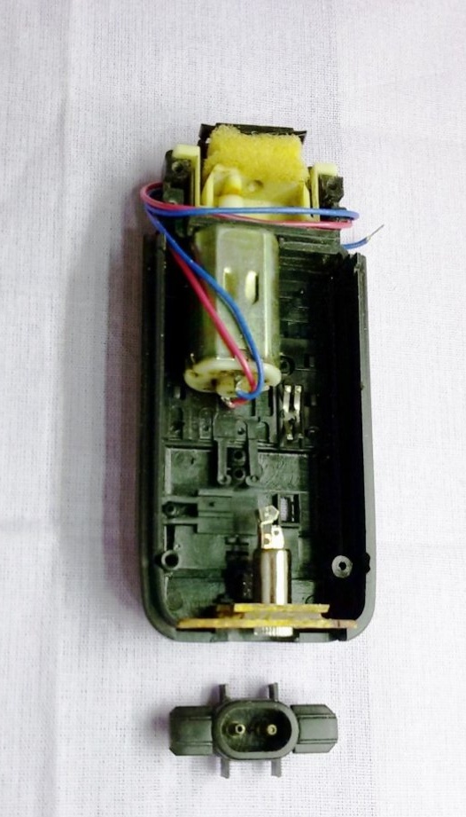
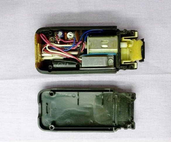
To analyze the reasons for the failure of the structure, we will analyze the razor, for which we unscrew the four screws from the back of the case - a self-tapping screw and open the back cover.

We remove the built-in charger board from the case and disconnect the soldered battery.
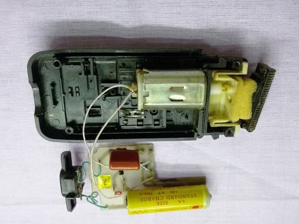
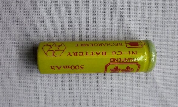
An AA-size battery with a capacity of 500 mAh installed in a Ni-Cd razor has become unusable in appearance and voltage and current measurements (loss of capacity).
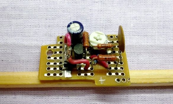
The reason for the long charging time and rapid failure of the battery was the Chinese "thrift" - the maximum simplification of the charger built into the electric shaver. Its actual layout is shown below.
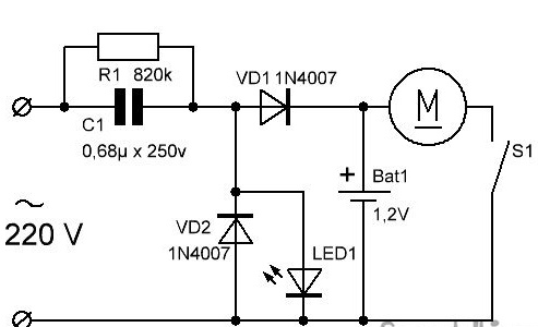
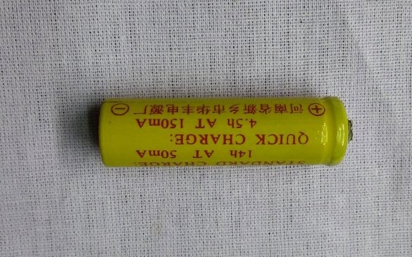
This charger (charger) is made at low power output. The output charging current of this charger is below 20 mA, which is 2.5 times lower than the standard charging mode for the battery installed in the razor and 7.5 times lower than the possible fast charging mode. These data are indicated on the battery itself (see photo above). In connection with such a simplification of the charger circuit, instead of 14 hours of charging in standard mode, the battery had to be charged from zero to full capacity for more than 30 hours.Therefore, an incomplete discharge after shaving, an incomplete charge due to the low current and lack of hours in a day, as well as the effect of the “memory” of a Ni-Cd battery, quickly made it unusable.
With the existing memory, replacing the battery with a new one does not make sense, it will be waiting for the same fate. For normal operation of the razor, it is possible to increase the output current of the charger by increasing the capacitance of capacitor C1 to two microfarads (by 450 or 600 volts) and turning on the LED indicator through the limiting resistance. However, the use of a rechargeable razor requires constant monitoring of it - do not forget to charge it, turn it off in time, periodically conduct a full discharge-charge cycle. And the advantages of this design are minimal. Due to the fact that the autonomous operation of this electric shaver is practically inexpedient, it was decided to transfer it to power from an alternating current network of 220 V.
Initial data
At a supply voltage of 1.5 V, the razor motor consumes 0.6 ... 0.8 A current in operating mode, and up to 1.4 A in start-up mode. The resistance of its winding is about 0.3 ohms.
Shaver Making
1. Choice of scheme
Due to the large current consumption of the electric motor, the transformerless power supply circuit for the electric shaver from the 220V network disappears. The transformer power circuit does not fit into the small dimensions of the razor. The output will be the use of a pulsed circuit for converting AC 220V into a constant voltage supply to the razor's electric motor.
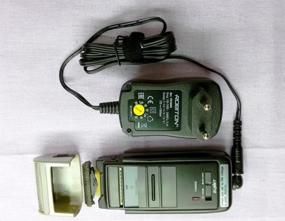
Such schemes are available, but not the simplest in terms of components, manufacturing and commissioning. Therefore, we will go in a simpler way - we will purchase a ready-made switching power supply unit (UPS) - a universal network adapter with 220V to 3 ... 12 V and a load current of up to 1.0A. A bonus to the purchase will be stabilization of the output voltage and protection against short circuits and overloads.

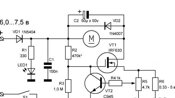
When using a razor, the load on the knives often changes, therefore, the engine speed and the current consumed by the engine change. In addition, the maximum current of the UPS is limited to 1.0 amperes, which is less than the inrush current of the razor. To eliminate the influence of these problems, we will manufacture and install a current stabilizer in the razor body according to the diagram below.
2. Description of the current stabilizer circuit
The current stabilizer of the razor electric motor is made on transistors VT1, VT2.
The razor is turned on by the S1 slide switch located on the razor's standard board. The current from the UPS through the diode VD1, which protects the circuit from incorrect switching, is supplied to the electric shaver M, then to the field effect transistor VT1 and the limiting resistor R6. The main current passes up to 1.0 amperes along this power circuit, therefore all component parts must have a margin of current.
Resistor R6 is a starting current limiter, also serves as a current sensor, has a low resistance (0.33 ohms) with a power of up to 5 watts. A voltage proportional to the voltage on the current sensor is removed from the backup resistor R5 and is supplied to the control transistor VT2. With increasing current on R6 (R5), the voltage drop increases on it, transistor VT2 opens slightly, reducing the voltage at the gate of transistor VT1. This leads to a decrease in current through VT1 and stabilization of the current in the motor circuit. With a decrease in current, reverse processes occur through R6 (R5).
Manual adjustment of the tuning resistor R5 allows you to adjust the current and set the optimal engine speed. The boundary voltage at the gate of the transistor VT1 is set by selecting the resistance of the resistor R2. Capacitor C2 and diode VD2 optimize engine performance.
3. The manufacture of a current stabilizer
As an indicator of inclusion, we use a standard LED. We use the electric motor, circuit board and power switch available in the shaver. We purchase or select from the available, missing radio components to complete the circuit.Pre-fix the direction of rotation of the motor or the polarity of its connection.

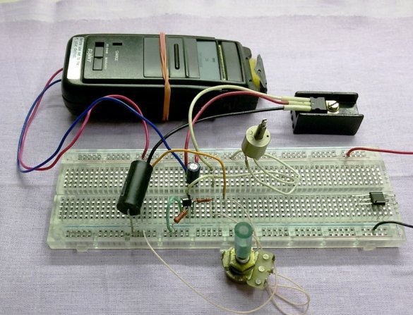
We place the parts of the current stabilizer on a universal circuit board. We collect the razor outline completely. The adjustment resistor R2 is replaced by a variable of 1.0 mOhm.
We replace the standard network connector with another one corresponding to the UPS connector. The base of the connector can be made of a 1.5 mm thick textolite sheet with additionally glued overlays to prevent the connector from rolling when the UPS is connected.
We completely free the razor board (except for the standard LED) from the installed memory elements. In the free space of the board, to the right of the engine, we install the limiting resistor R6 and the field effect transistor VT1 on a makeshift radiator. The radiator is made of 1.5 mm thick aluminum sheet. The dimensions of the radiator are determined by the free space in the housing. The lower contact part of the radiator is made in the form of a square and is fixed to the board with an M3 screw through the washer to create a gap and increase heat transfer from below. The upper additional part of the radiator is fixed to the same screw.

According to the size of the free space in the razor case, after installing the above elements, we cut out the working board for the remaining radio components. We solder the circuit to the board.
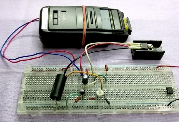
Elementally assemble the design of the electric shaver in a single unit.
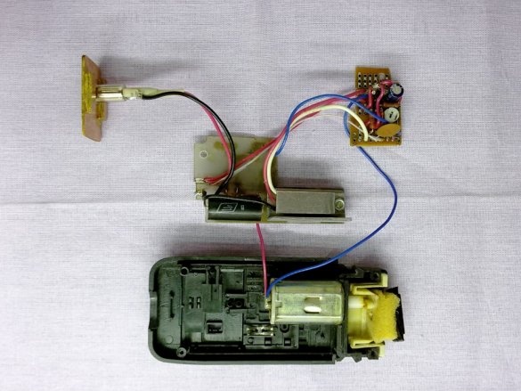
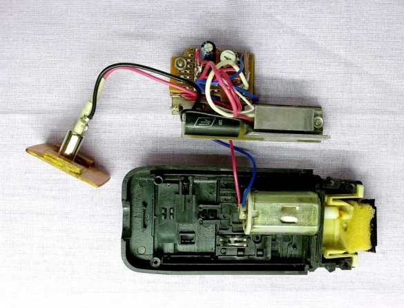
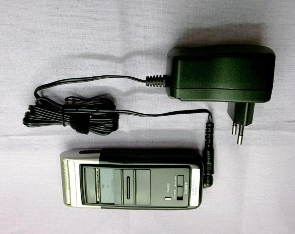
Finally, we adjust the operating mode of the electric shaver, assemble the case and use the fruits of our labor.