
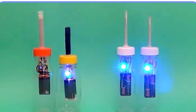
In this article, the author of the Thomas Kim YouTube channel tells you about a simple electric field strength detector. With this device, you can even detect lightning discharges, not to mention ordinary static electricity.
The device is made of a minimum of parts that are not difficult to find.
Materials
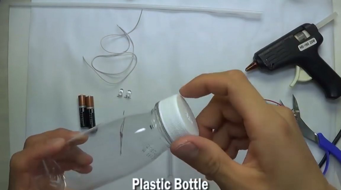
- A small plastic bottle
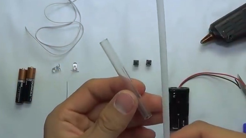
- Battery holder
- Two 1.5V AAA batteries
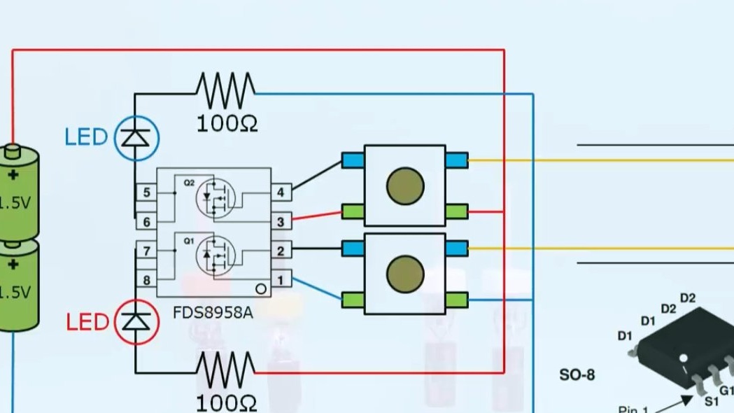
- Red and blue LEDs
- Two clock buttons
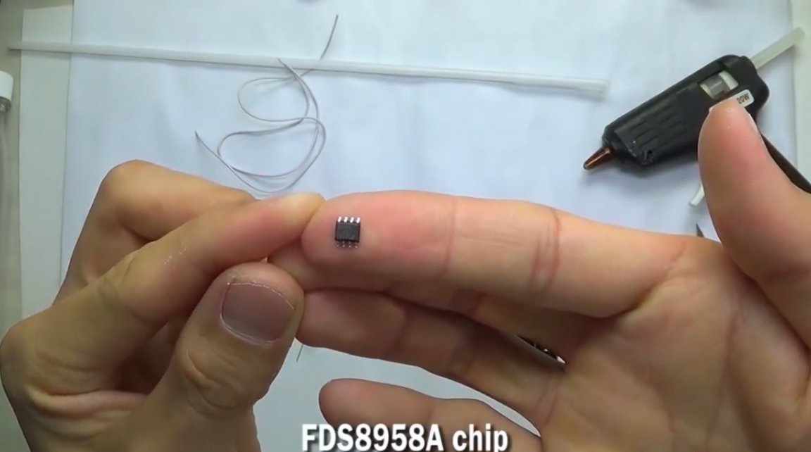
- Transistor Assembly FDS8958A
- Two 100 Ohm resistors
- Plastic and glass tubes
- Wires.
Instruments, used by the author.
-
-
-
- Nippers
- Generator Van de Graaff.
Manufacturing process.
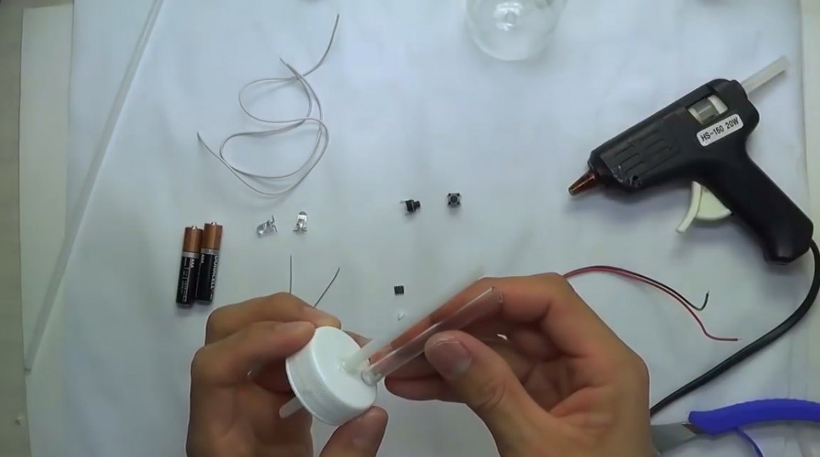
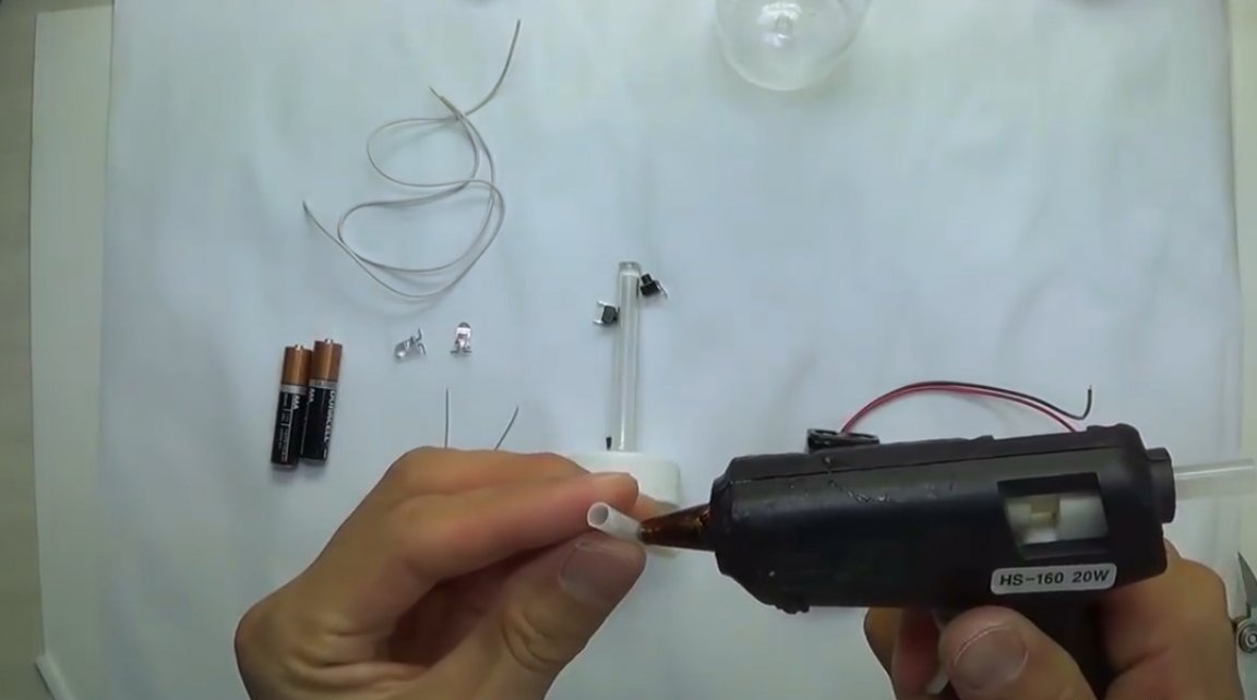
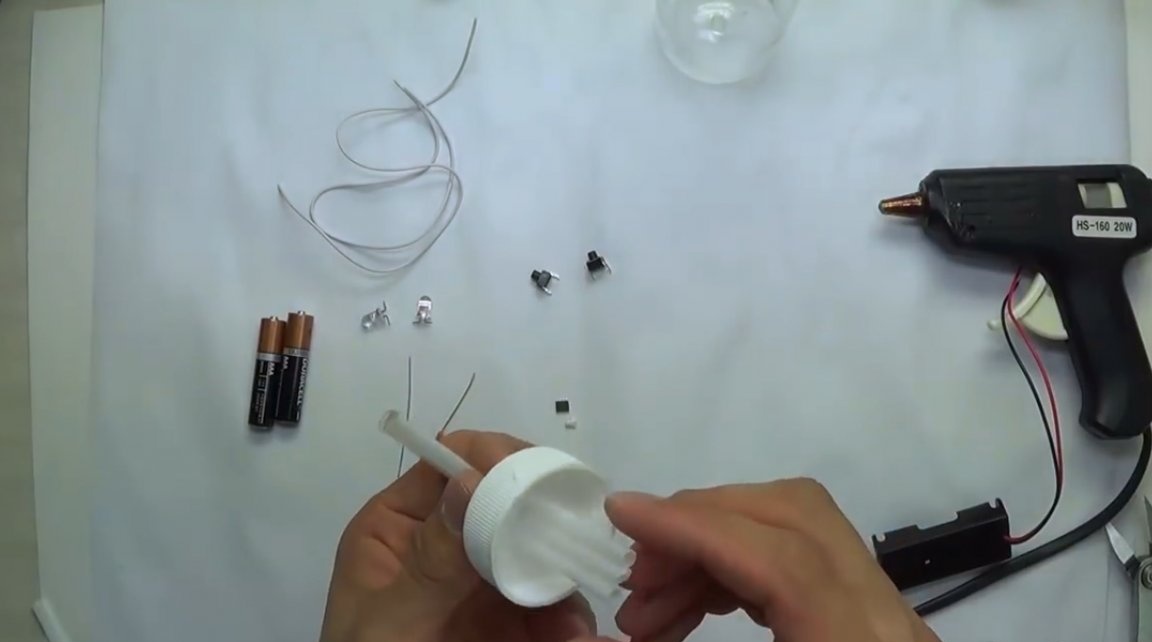
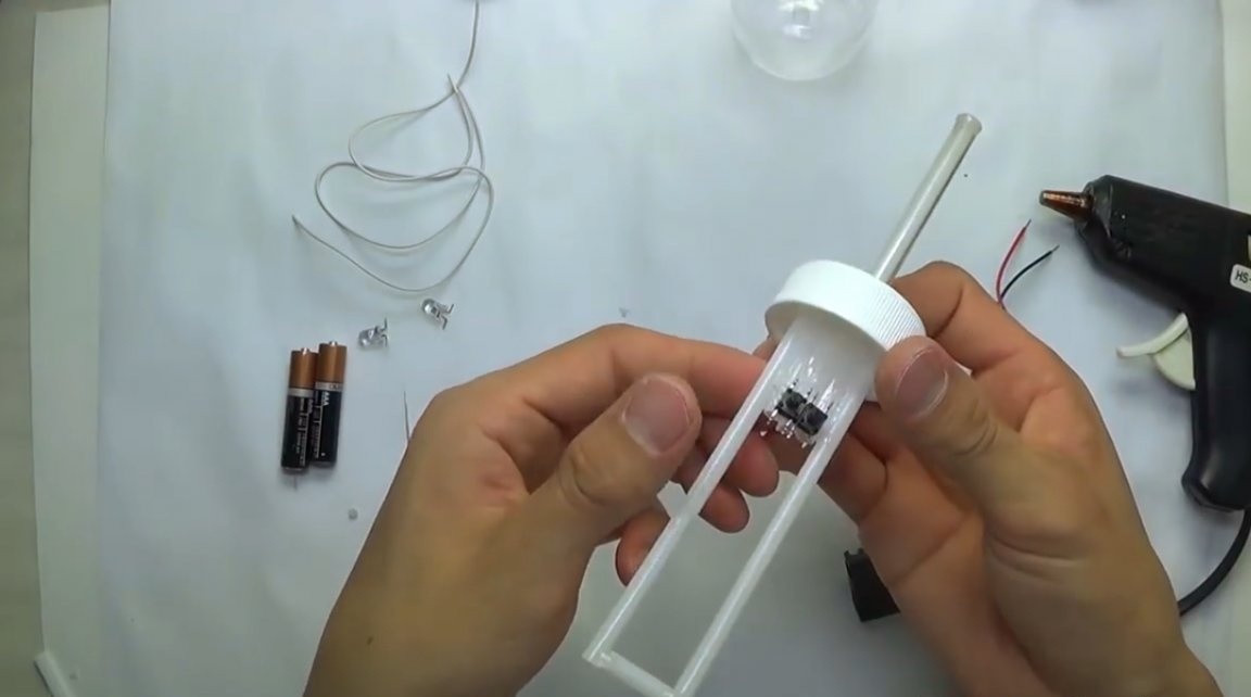
So, for starters, the wizard prepares the case for the device. Drills a hole in the center of the lid, and inserts a plastic tube into it.
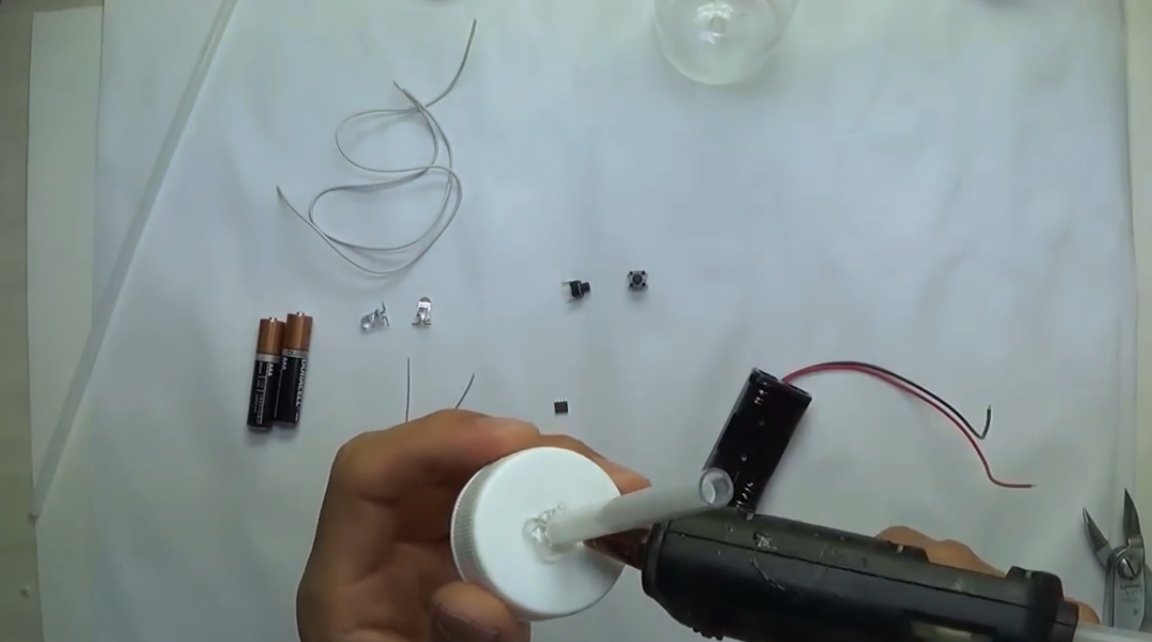
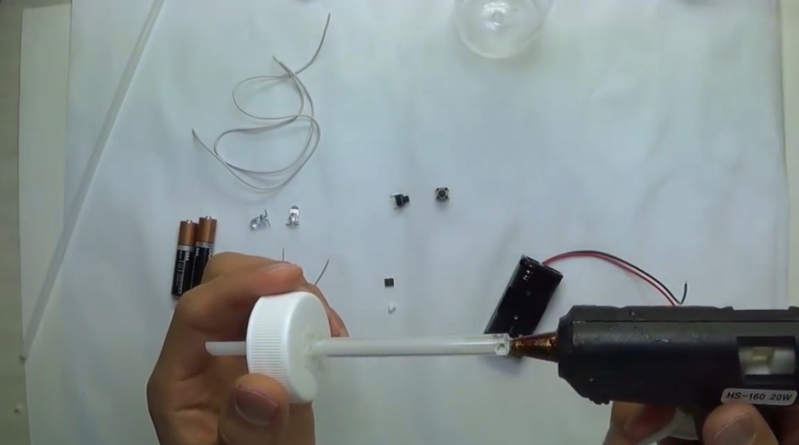
Having cut it to the desired length, fixes it with hot-melt adhesive on the back of the lid.
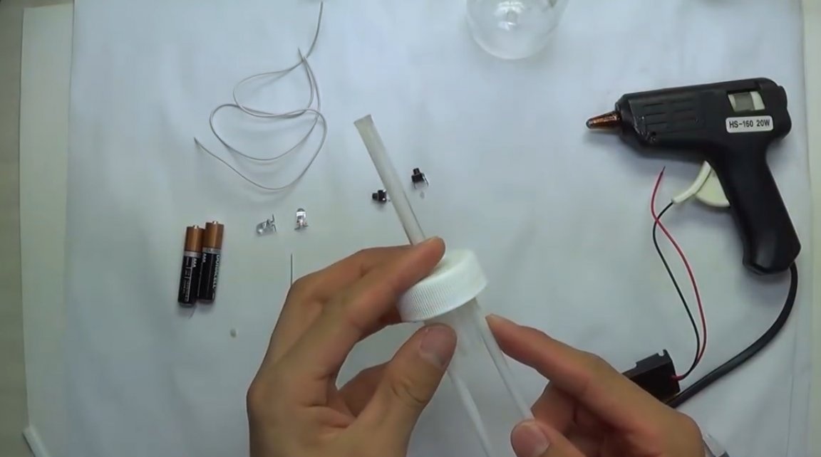
Then cut the tube a little shorter than the glass.
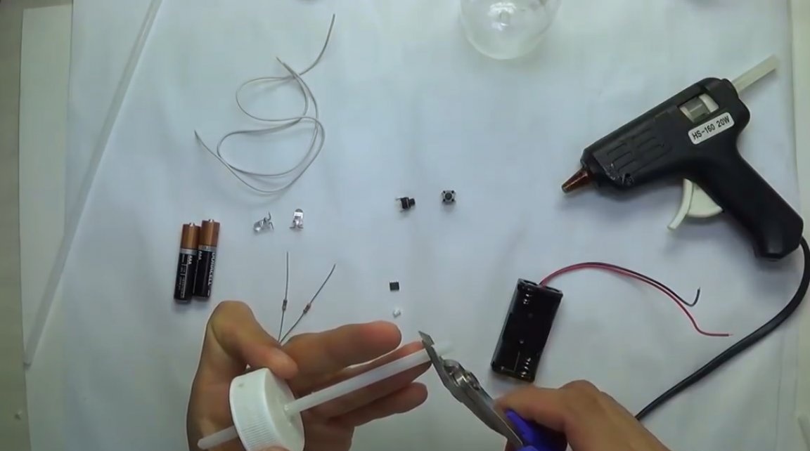
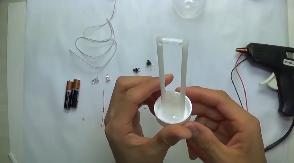
Having put a glass tube on a plastic one, fixes it with glue at the base and at the end. It should be as tight as possible.
On the underside of the lid, an electronic frame is made from tube scraps.
Further, the device will be assembled as follows.
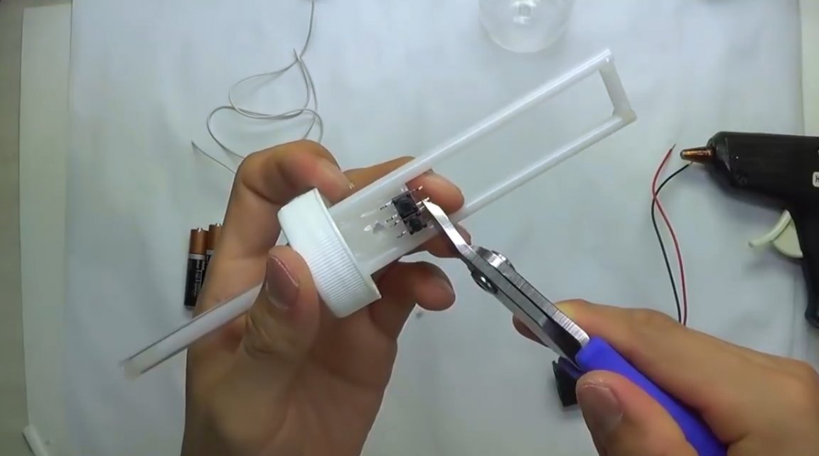
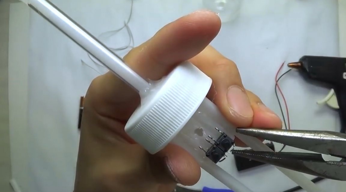
Having spread the legs of the buttons, glues them to the frame. They are needed only for soldering microassemblies. They do not perform any other function. They can be replaced with scraps of legs from resistors.
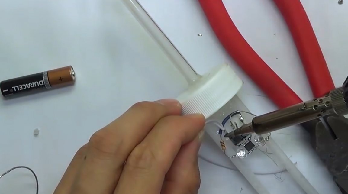
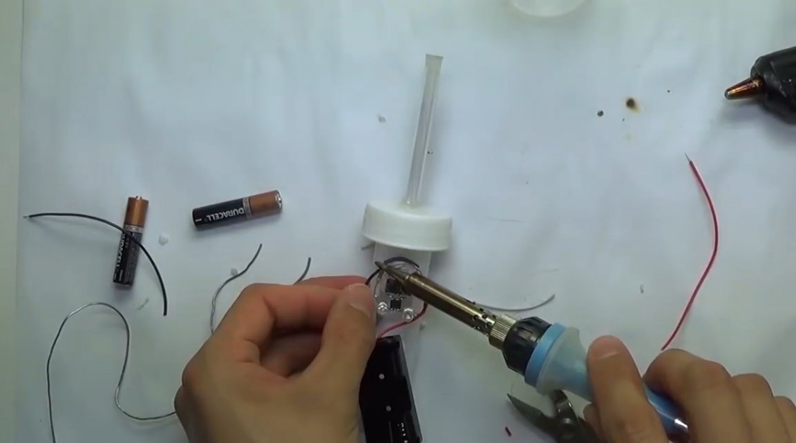
Then the author makes a hole in the central tube.
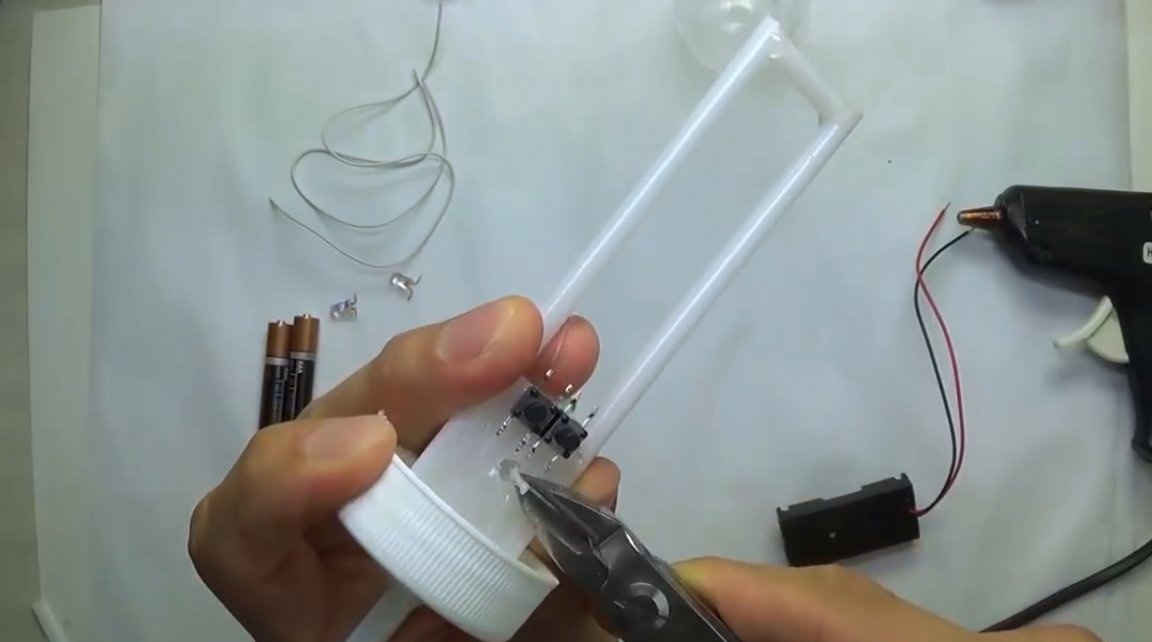
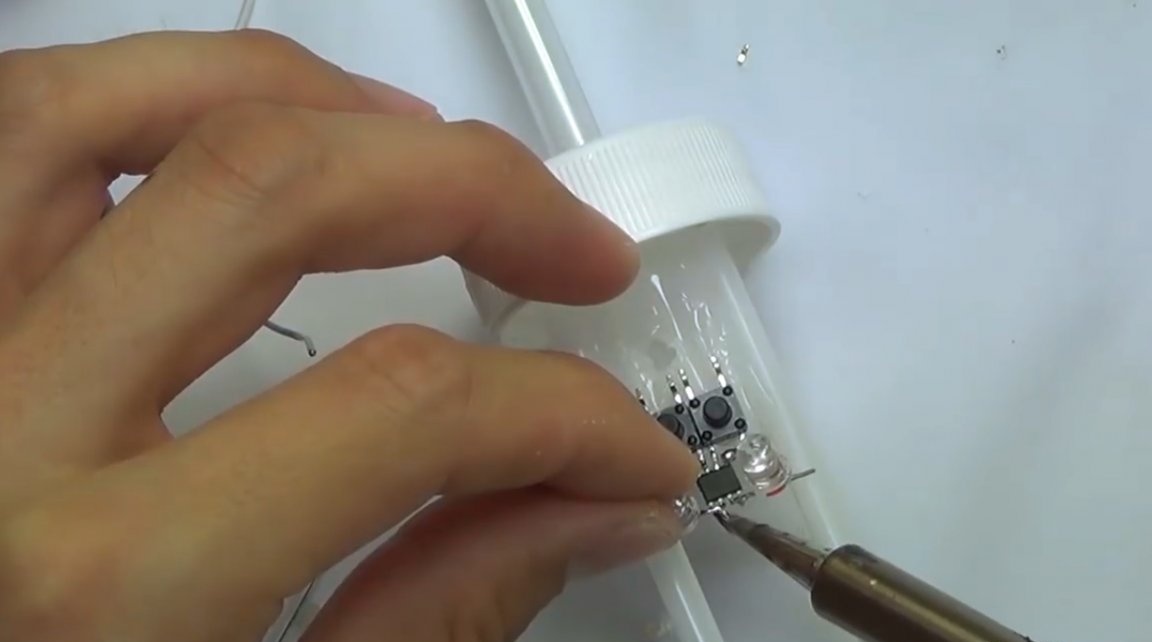
Shortens the two nearest legs of the buttons, and bends the distant ones so that it is convenient to solder the four legs of the transistor assembly.
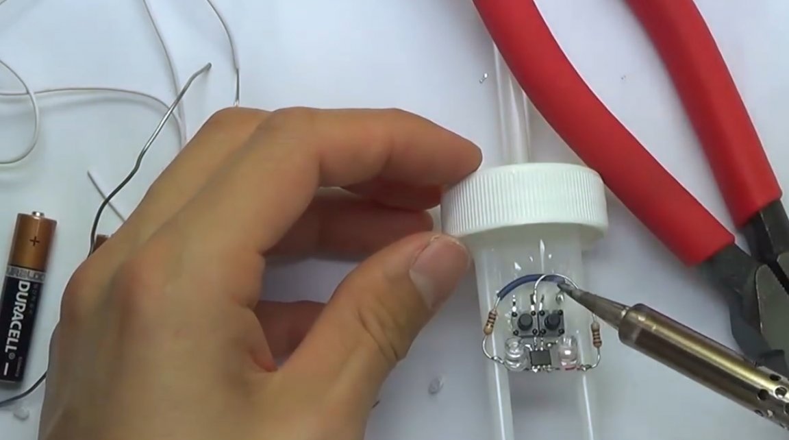
Now tins the contacts, and solders the transistor assembly. Namely, conclusions 1-4.
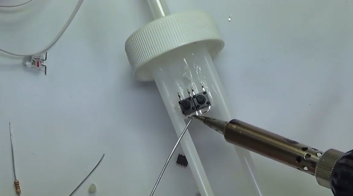
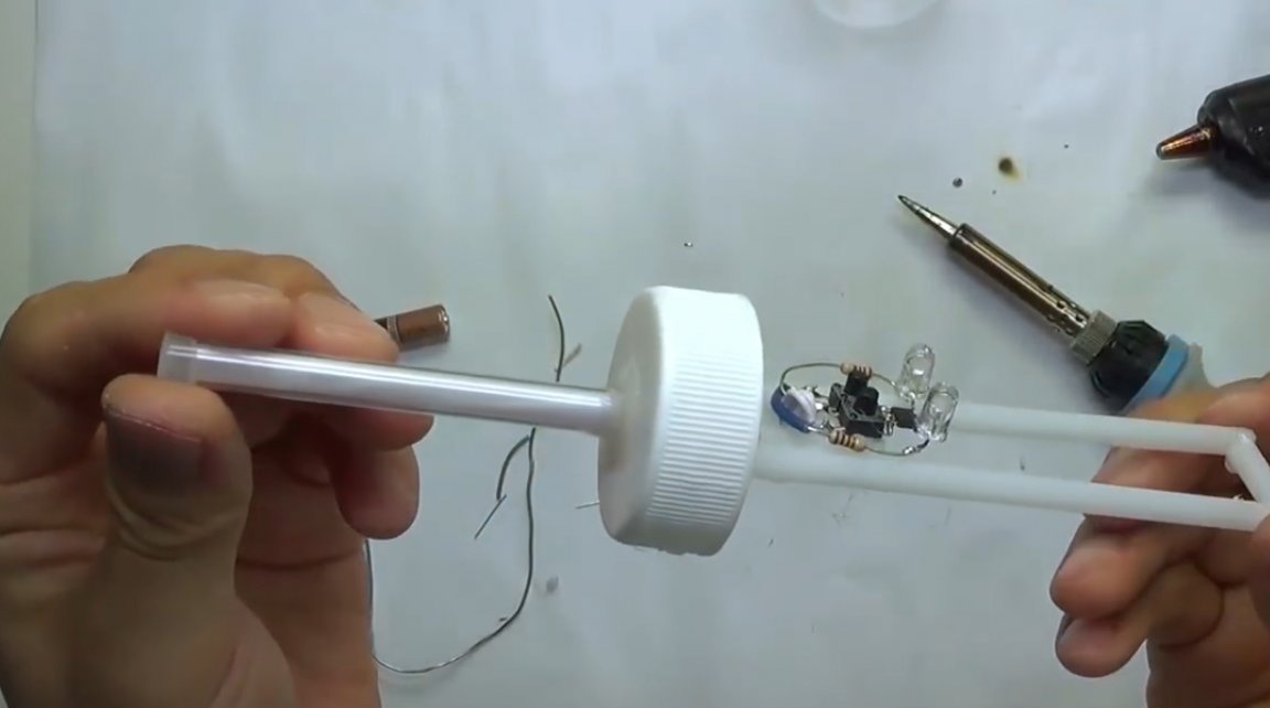
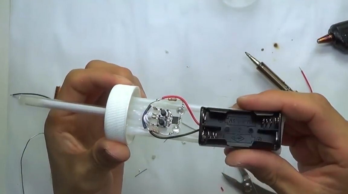
Solder to pins 5-6 plus blue, and to pins 7-8 minus red LEDs.
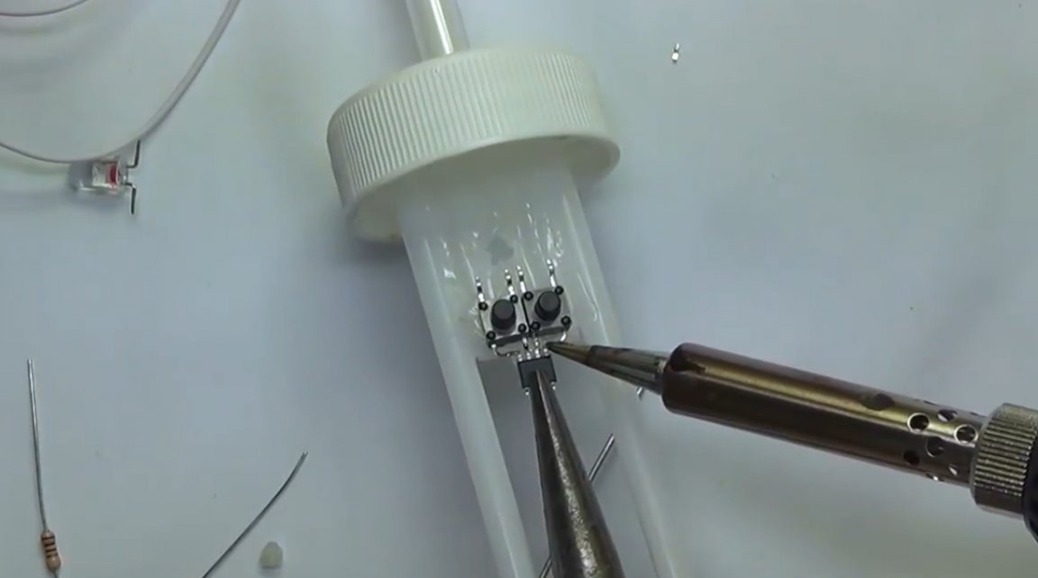
Then, 100 ohm resistors are soldered to the remaining terminals of the LEDs.
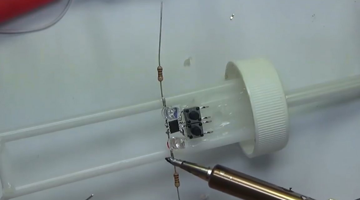
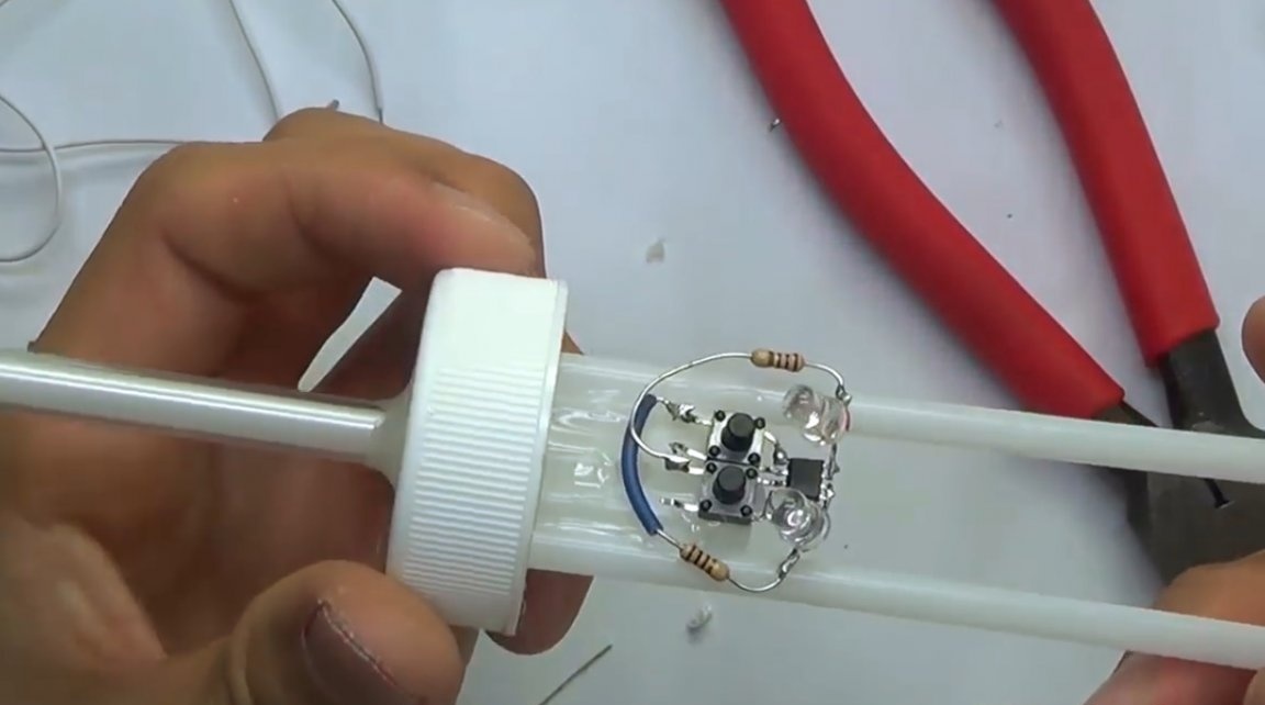
The resistor from the red LED is soldered to the button contact corresponding to the 3rd pin of the chip.
Having isolated the resistor output from the blue LED, it solders to the 1st contact.
So, the main part of the device is assembled.
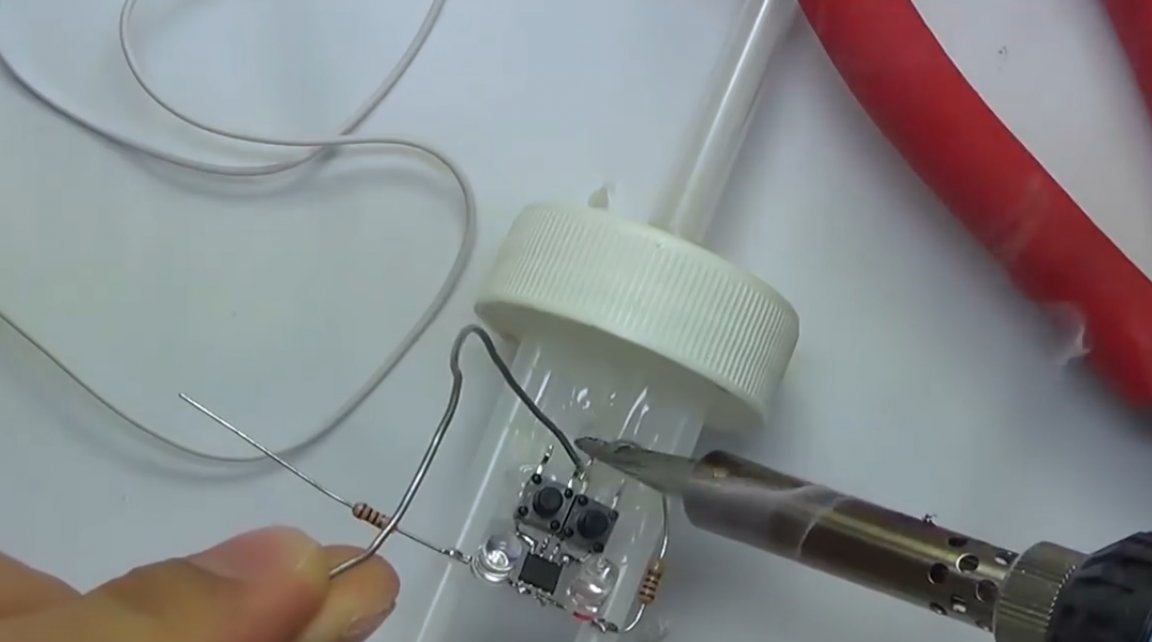
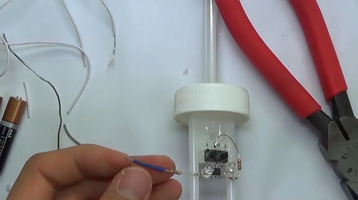
Of the two wires makes two antennas in the form of loops, and solders to the remaining contacts of the buttons. Or 2, 4 pins of the chip.
It remains to fill the antennas into the tube.
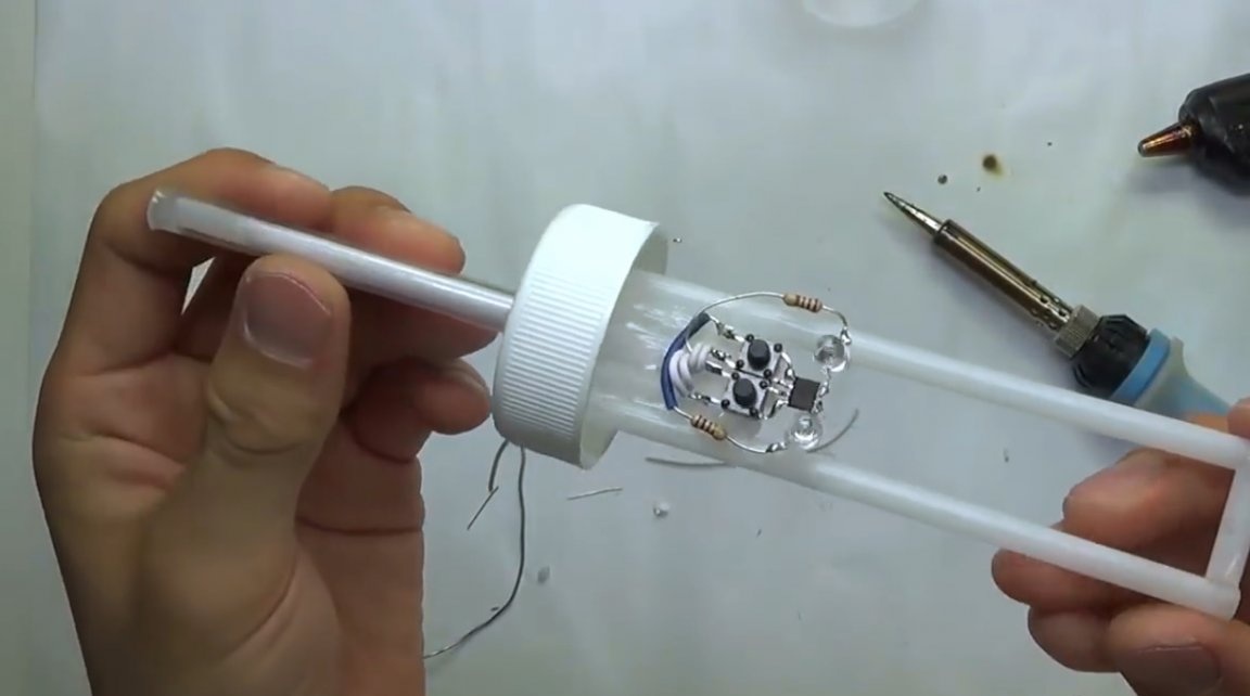
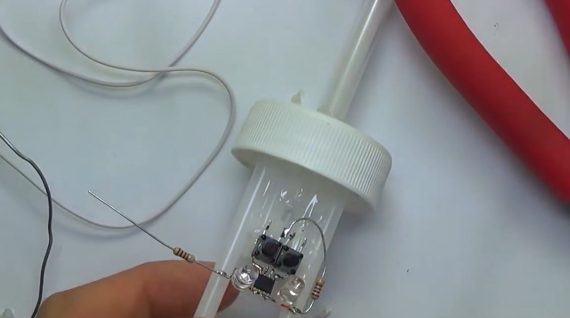
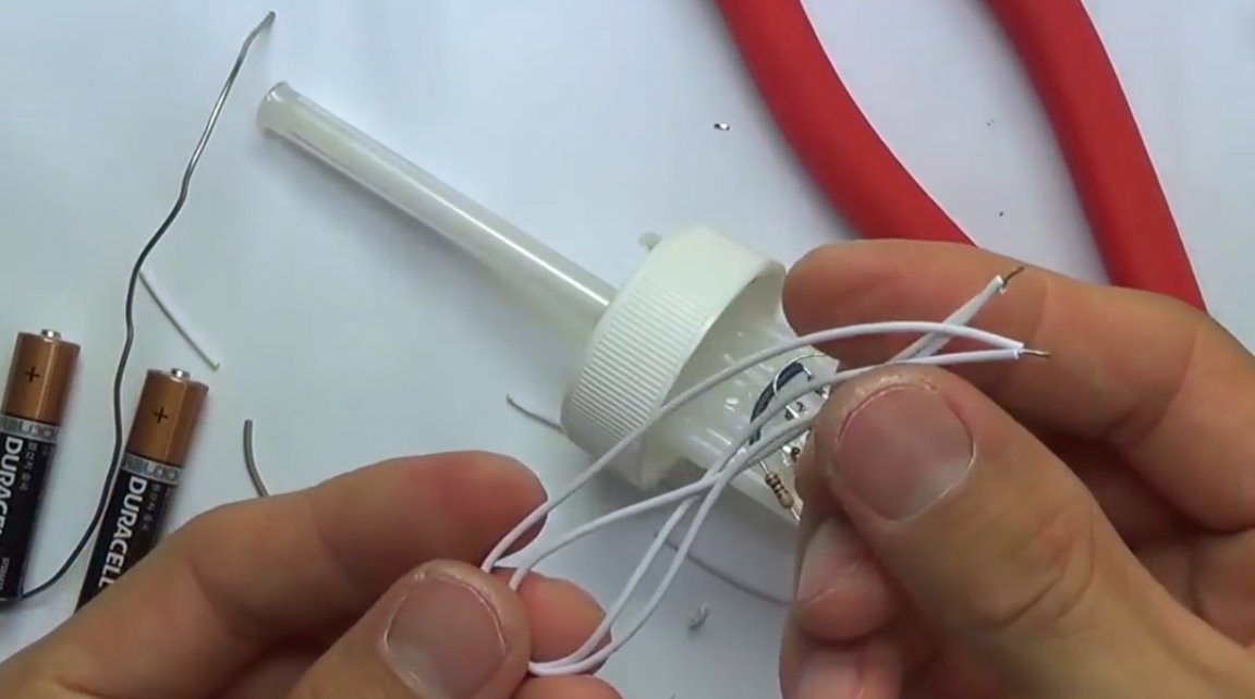
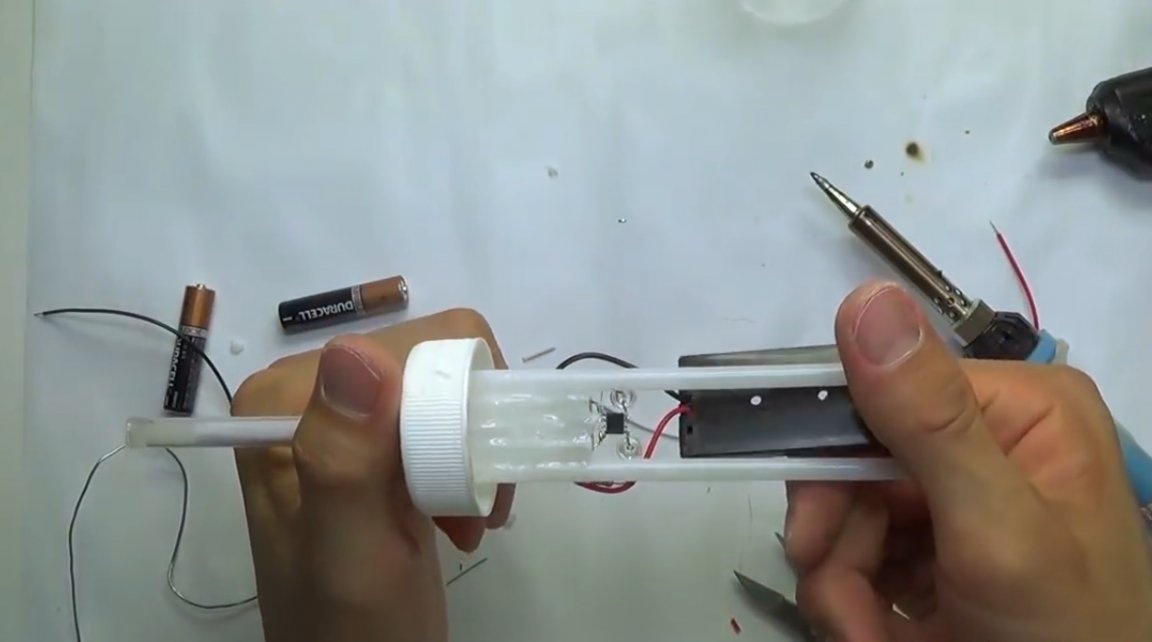
The last soldered contacts of the battery compartment directly to the terminals of the resistors.
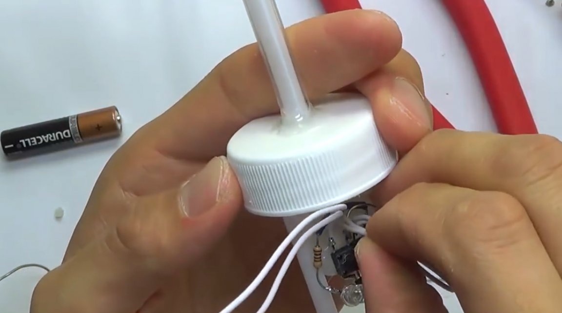
The battery compartment remains secured to the frame with hot-melt adhesive and close the lid.
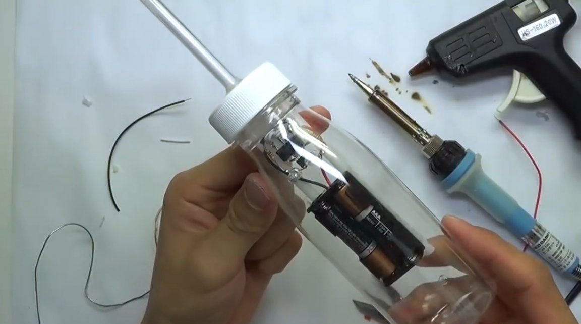
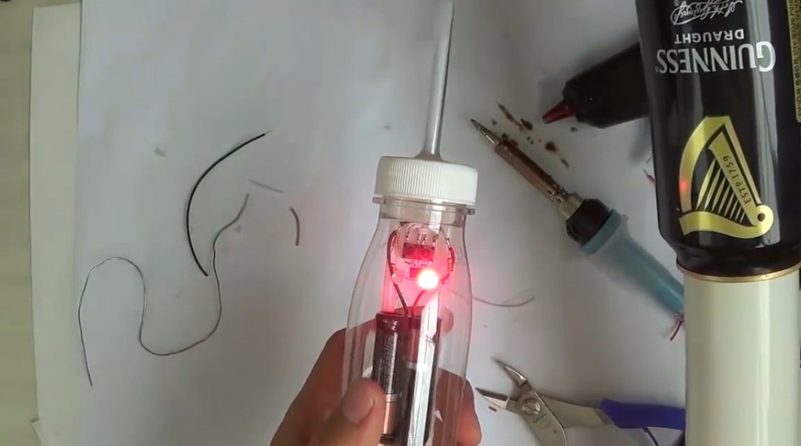
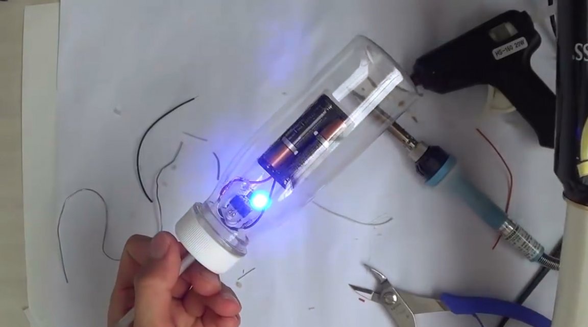
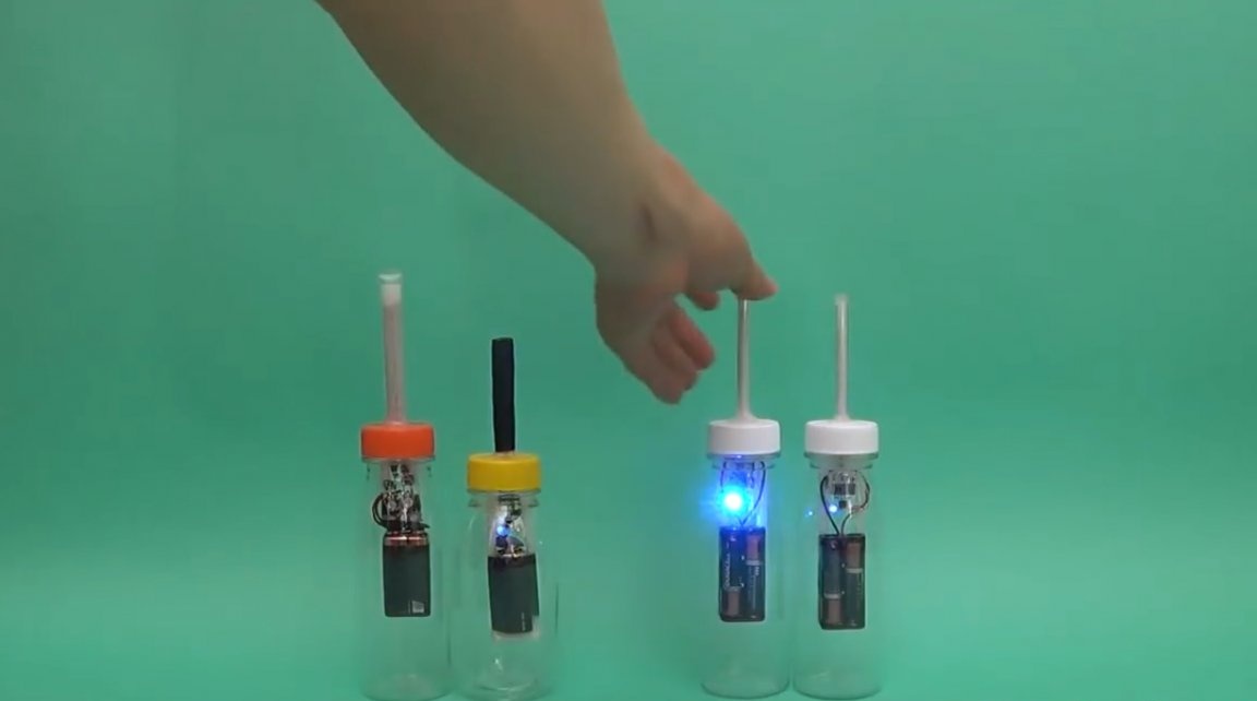
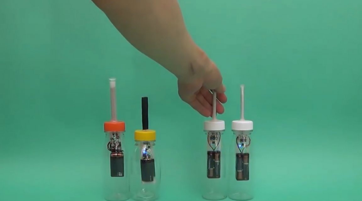
Turning on the Van de Graaff generator, the author checks the operation of the device. If you hold on to the case, you can see that there is a positive charge around. To check the operation of the reverse key - just grab the antenna.
Now checking with two different generators, one gives a positive discharge, and the second a negative one.
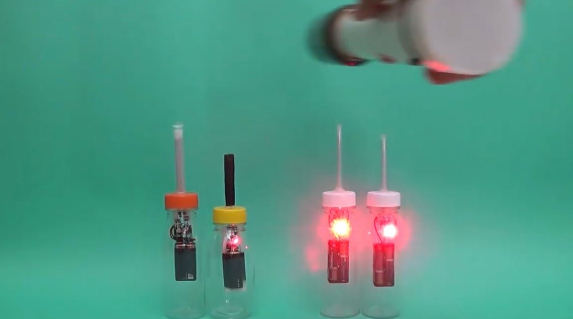
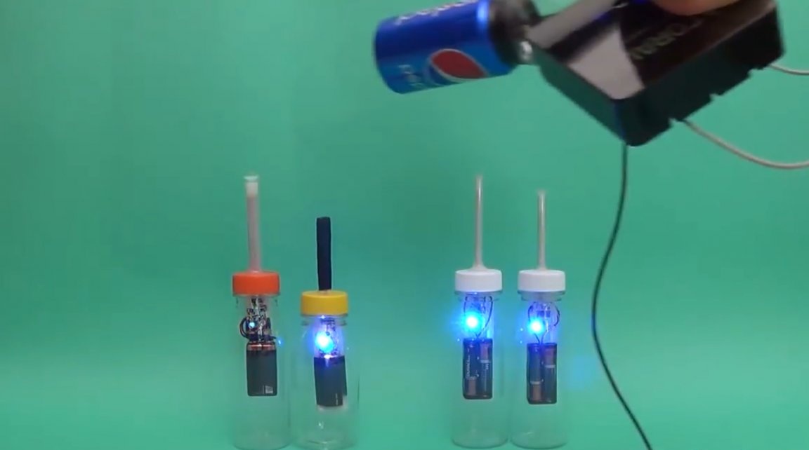
The device still remembers the accumulated charge for a long time, just touch the antenna to reset it.
Thanks to the author for a simple but useful device!
All good mood, good luck, and interesting ideas!