

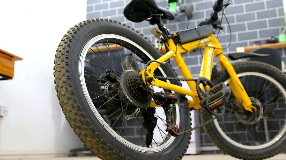
Previously, the foreman worked on converting his bike into an electric one, using a DC motor for an automatic door mechanism. He also created a battery designed for 84 V DC.
Now he needs a speed controller, which can limit the amount of energy supplied to the engine from the battery. Most of the speed controllers available on the network are not designed for such a high voltage, so it was decided to do it yourself.
In this project, an individual PWM speed controller will be designed and built to control the speed of large-scale DC motors.
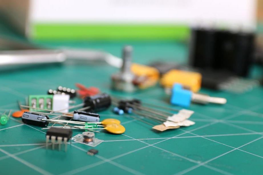
Step 1: Tools and Materials
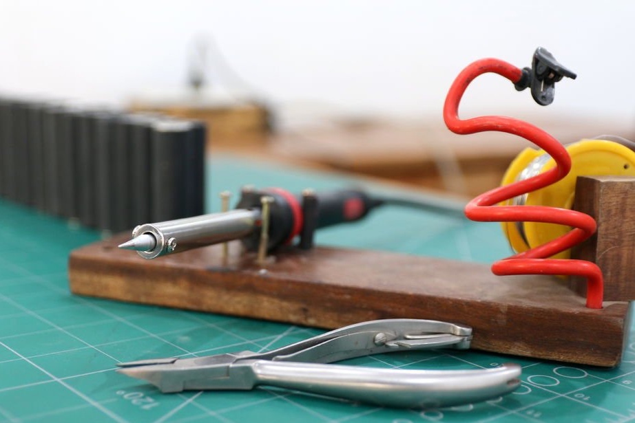
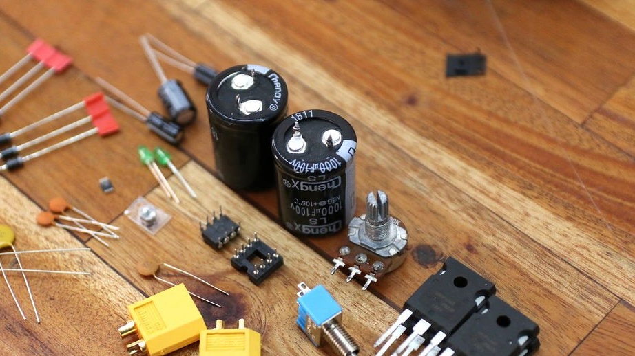
For this project, you will need basic soldering tools, such as:
- Soldering iron;
- solder suction;
- pliers;
Schematic, Gerber files and a list of components are available.
Step 2: Design a Speed Controller
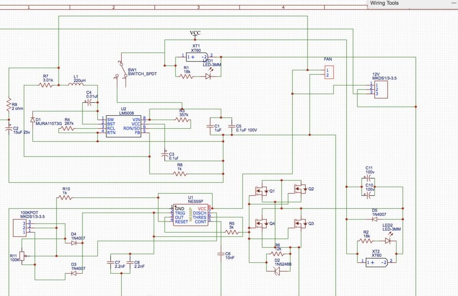
Since we strive to control the speed of the DC motor, we can use two technologies. The step-down converter, which lowers the input voltage, is quite complicated, so it was decided to use PWM Control (Pulse Width Modulation). The approach is simple to control the speed of battery power; it turns on and off with high frequency. To change the speed of the bicycle, the duty cycle or the time period for turning off the controller is changed.
Mechanical switches should not be subject to this high voltage at this time, so the Mosfet N-channel, which is specifically designed to handle a moderate amount of current at high frequency, is an appropriate choice.
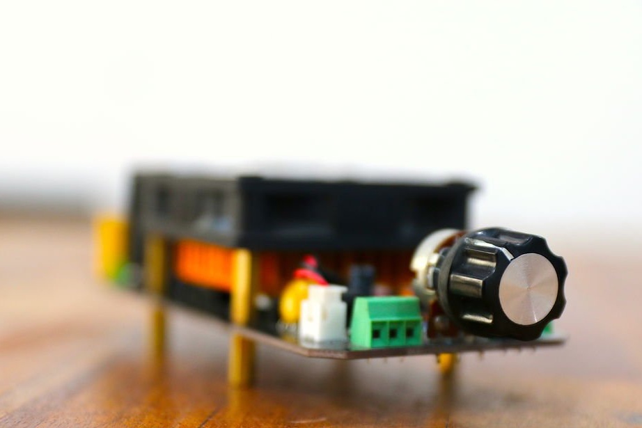
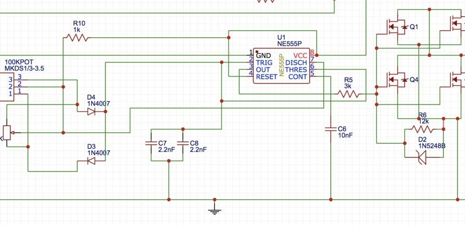
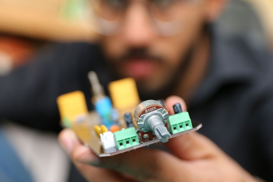
To switch the hemispheres, a PWM signal is required, which is generated by the IC timer 555, and the duty cycle of the switching signal is changed using a 100 kΩ potentiometer.
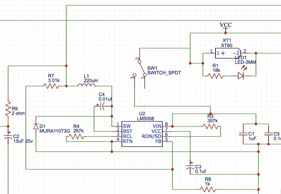
Since we cannot work with a 555 timer above 15 V, we will have to turn on the lm5008 converter integrated circuit, which lowers the input voltage from 84 V to 10 V DC, which is used to power the timer and cooling fan.
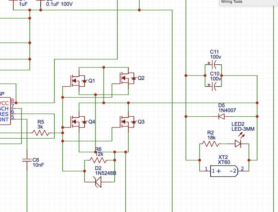
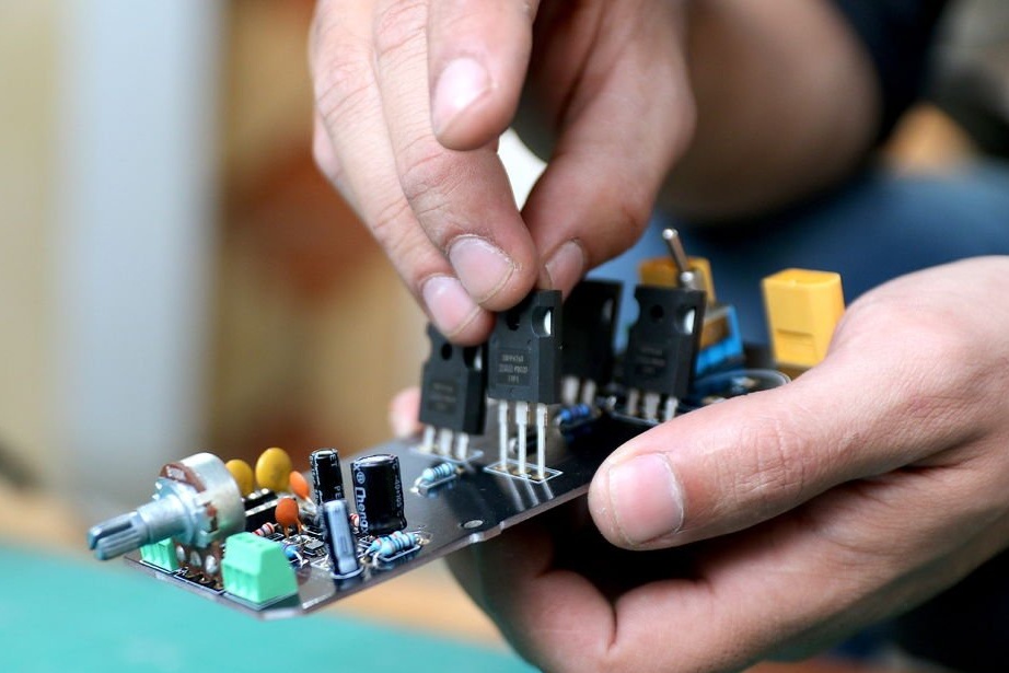
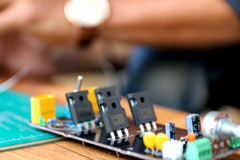
To process a large amount of current, four N-channel Mosfets were used, which are connected in parallel.
In addition, all additional components were added as described in the data tables.
Step 3: Design PCBs
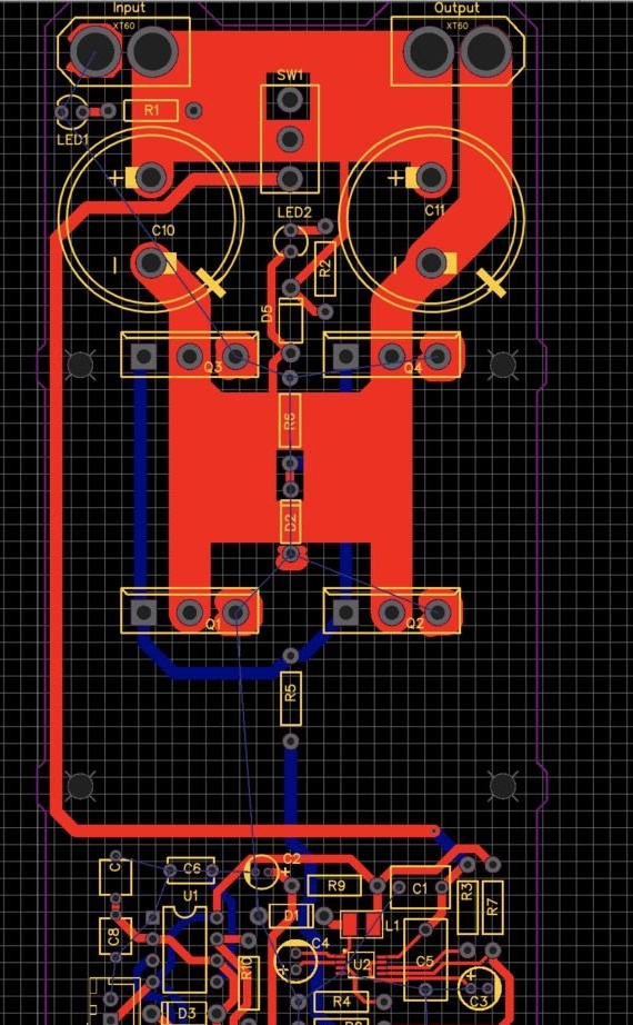
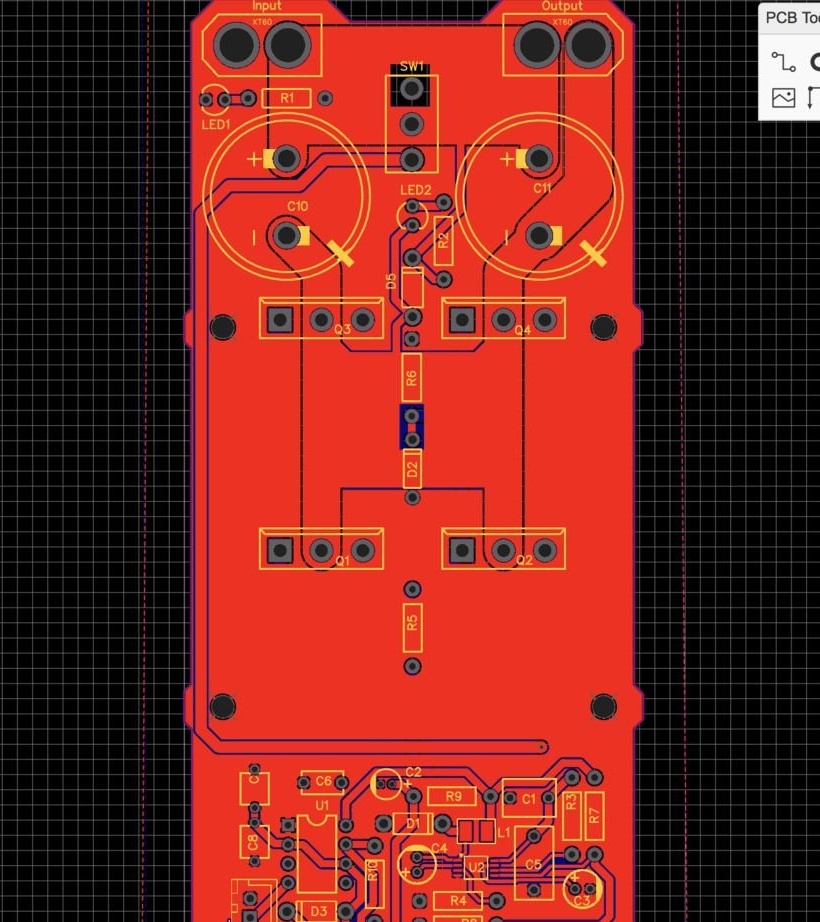
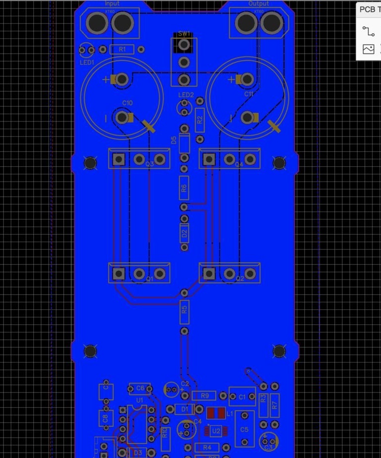
Having finished the circuit, it was decided to start developing a special printed circuit board for the speed controller. It was decided to design this device so that it was capable of further modifications for other DIY projects of the master who use large DC motors.
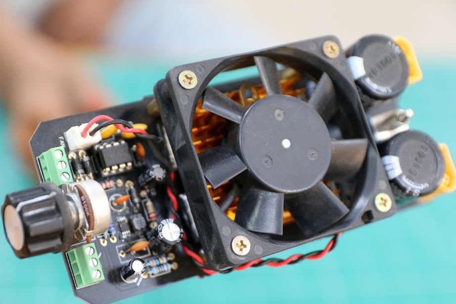
The idea of designing a circuit board may require a lot of effort, but it's worth it. Always try to design specific modules on the board on the other hand. Such modules include control circuitry and power. This is done so that when connecting everything together, you can choose the appropriate width of the print track, especially on the supply side.
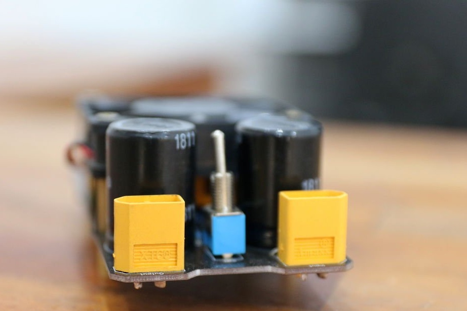
Four mounting holes have also been added, which will be useful for mounting the controller and holding the fan together with the heatsink over the MOSFETs.
Step 4: Order PCBs
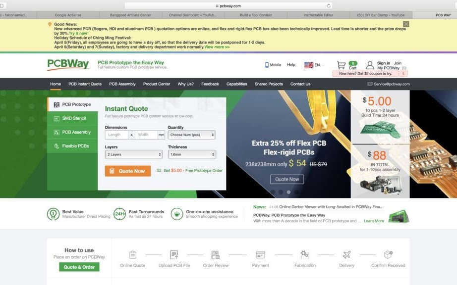
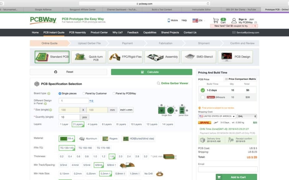
Unlike any other custom part for a DIY project, printed circuit boards are by far the lightest. Once the Gerber files for the final layout of the circuit board were ready, there were a few clicks left to order specialized circuit boards.
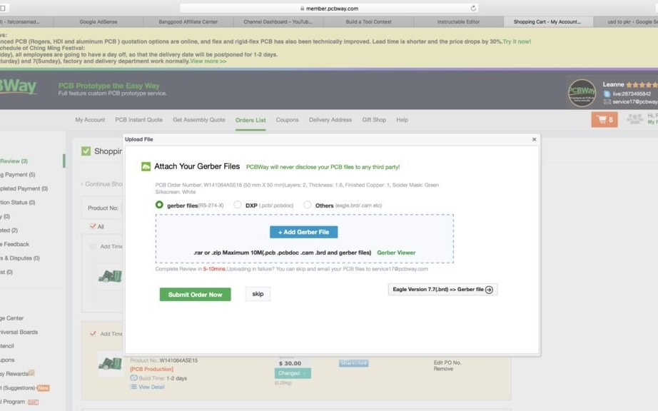
All that the wizard of this project did was go to PCBWAY and upload his Gerber files. After their technical team checks the design for errors, the design will be sent to the production line. The whole process will take two days and the printed circuit boards will arrive at the specified address within a week.
Gerber files, schematic and specification for the speed controller circuit board are available.
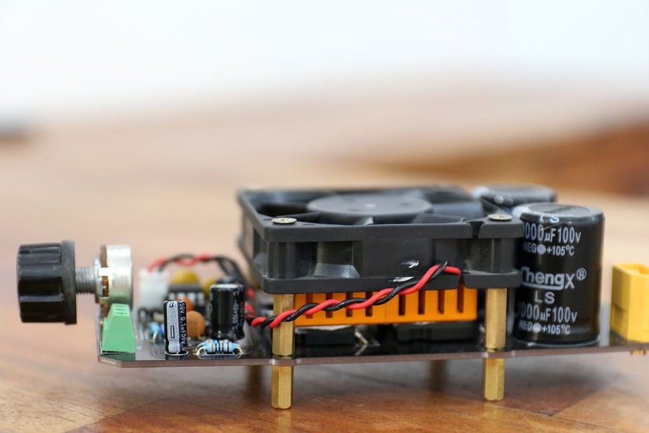
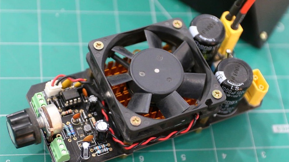
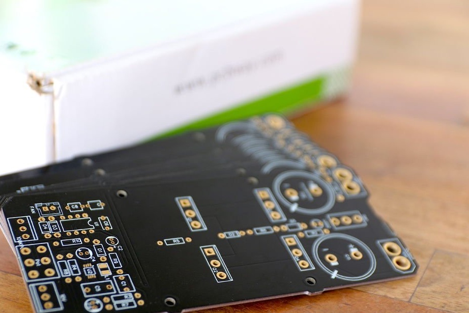
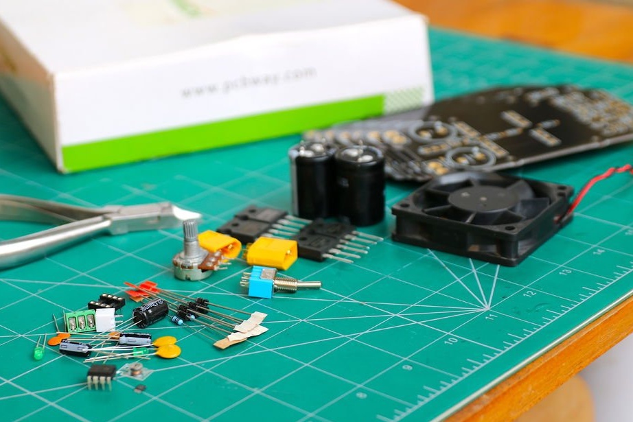
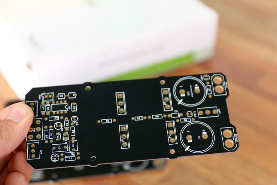
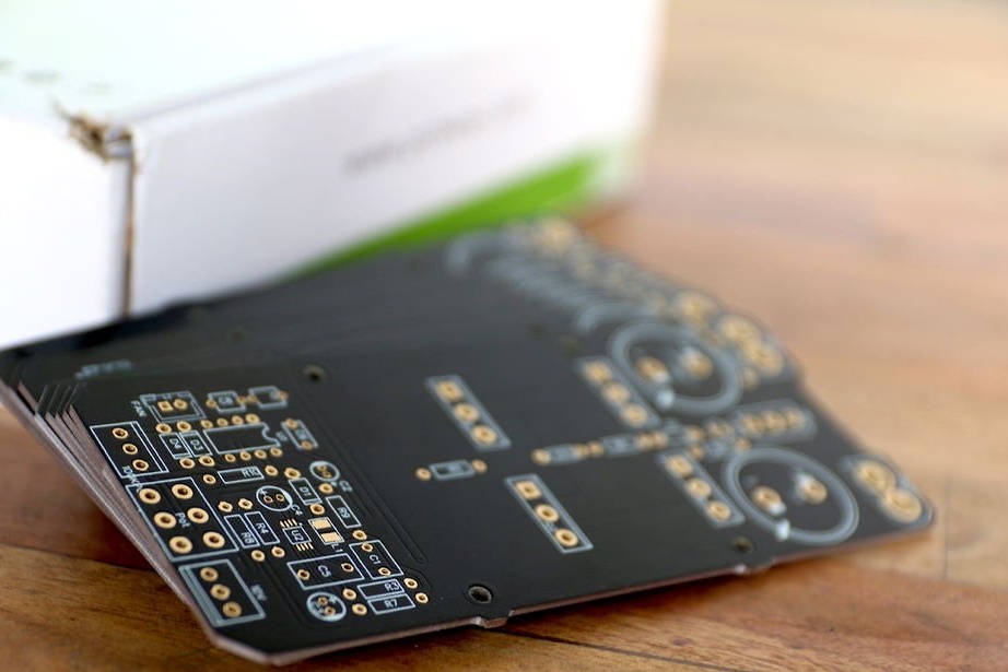
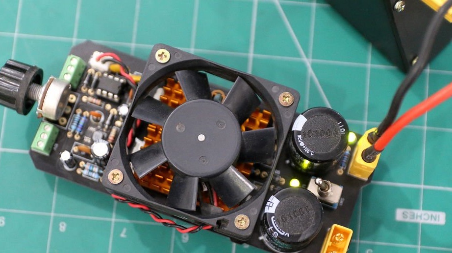
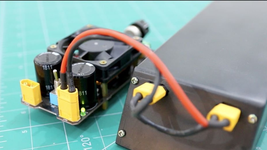
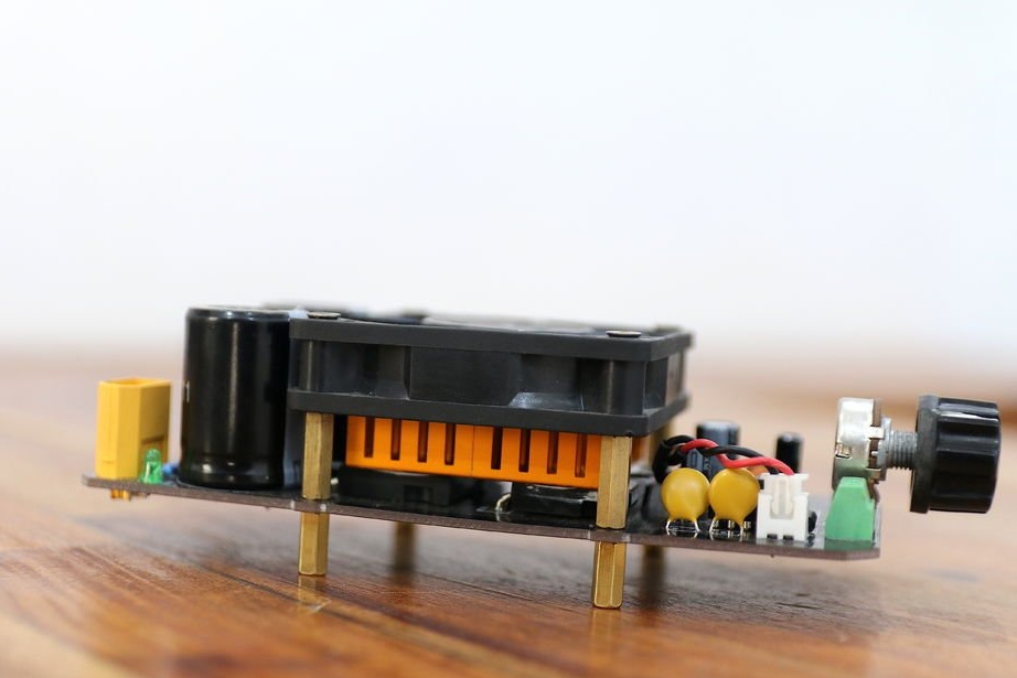
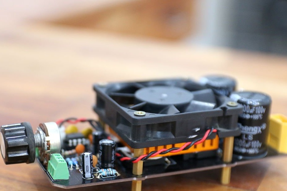
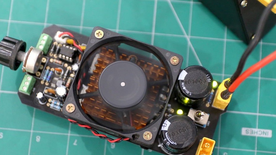
Step 5: Assembling PCBs
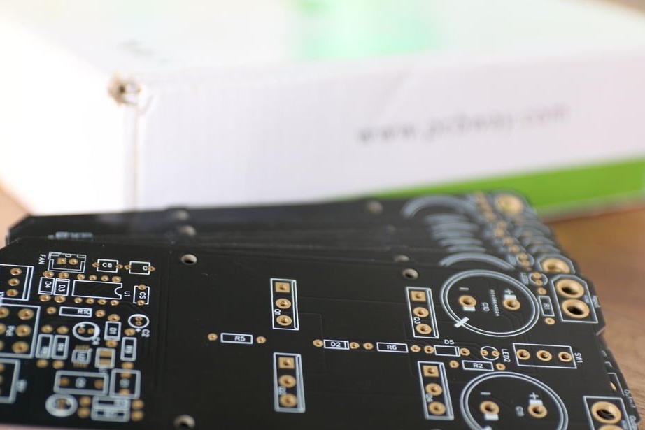
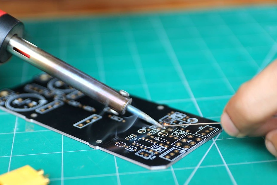
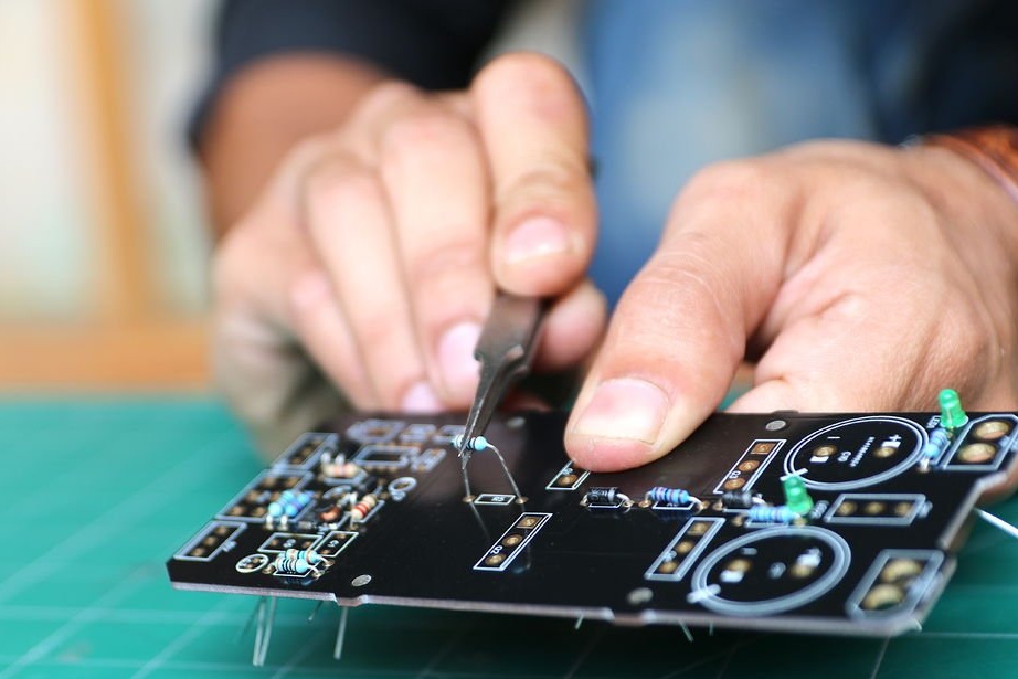
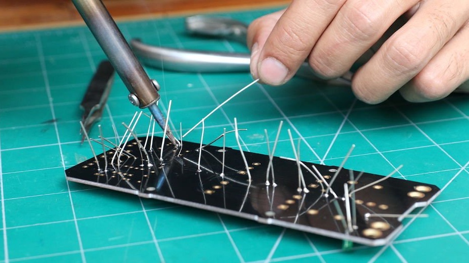
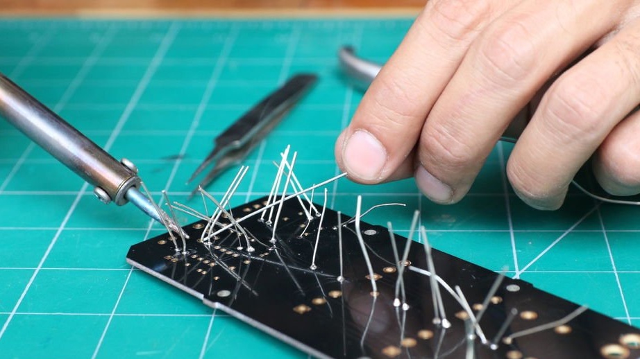
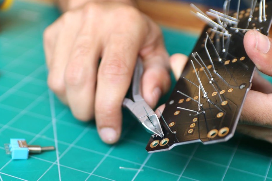
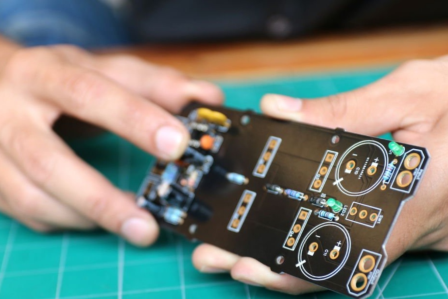
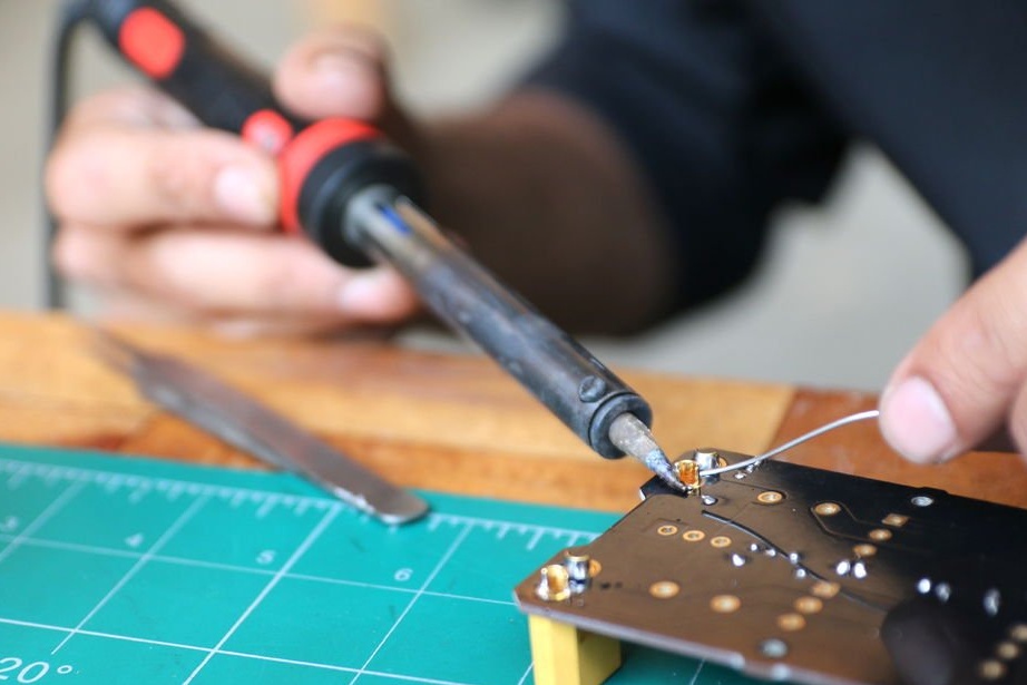
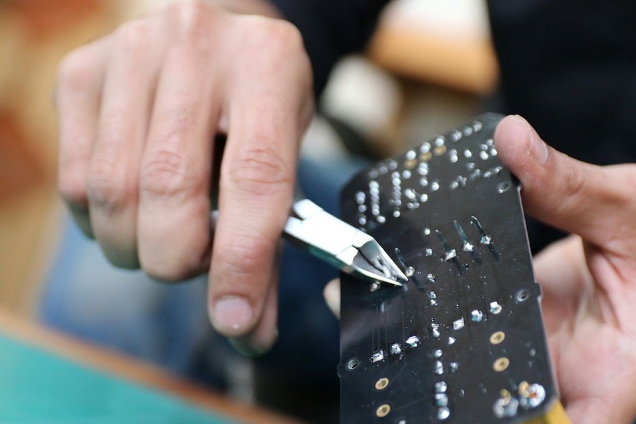
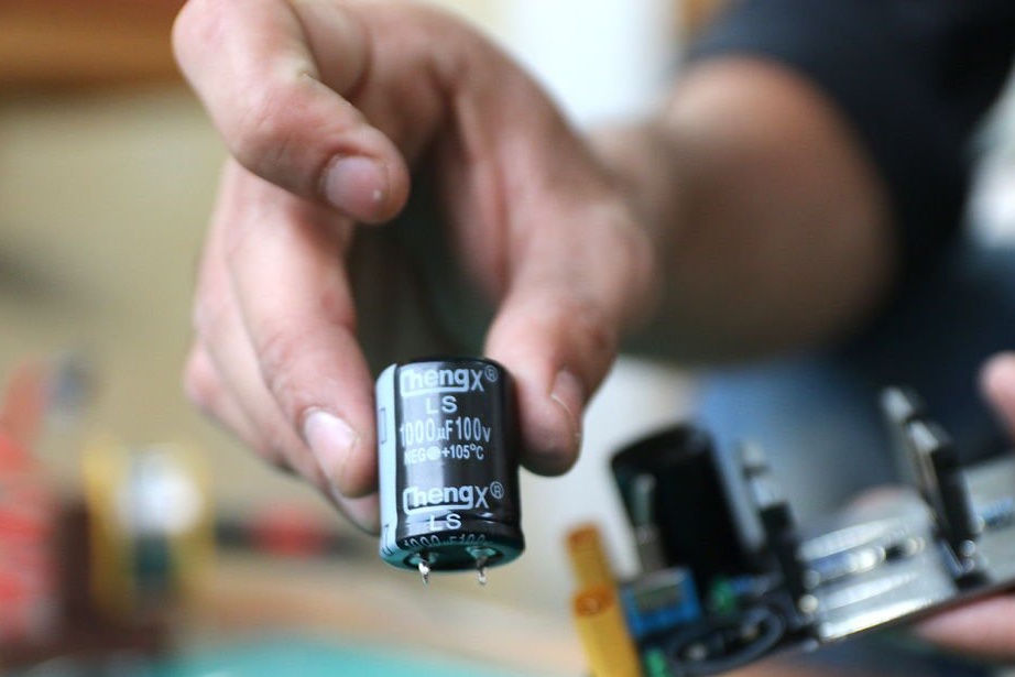
As expected, circuit boards arrived within a week. The quality of printed circuit boards is absolutely flawless. It's time to assemble all the components as indicated in the specification and put them in place.
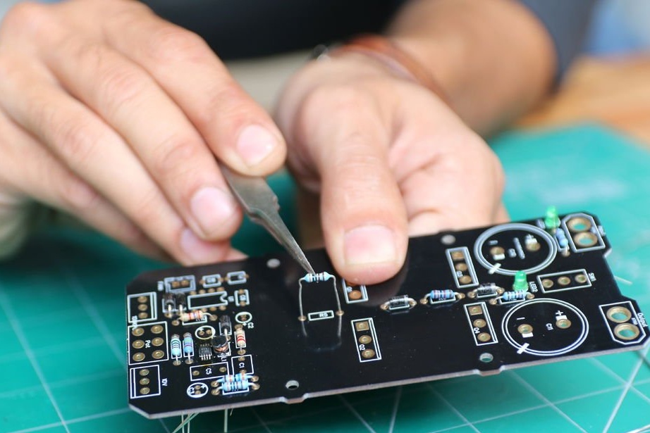
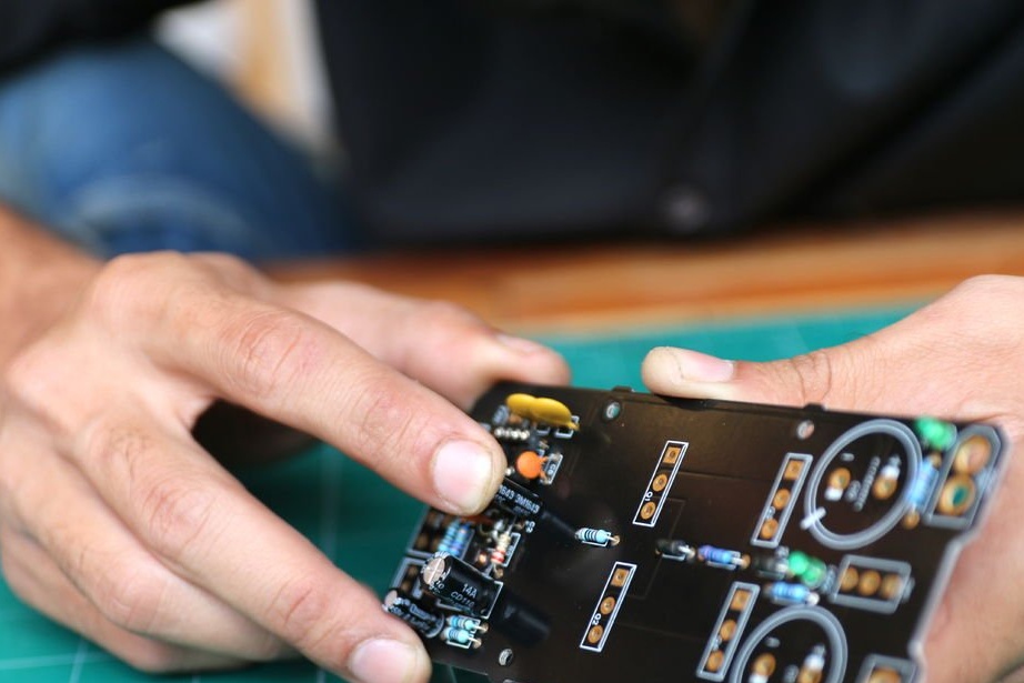
For everything to go smoothly, you need to start with the smallest component on the circuit board, which in our case is the LM5008 Buck converter, the SMP component. As soon as the components were soldered, according to the diagram, the master began to work with larger components.
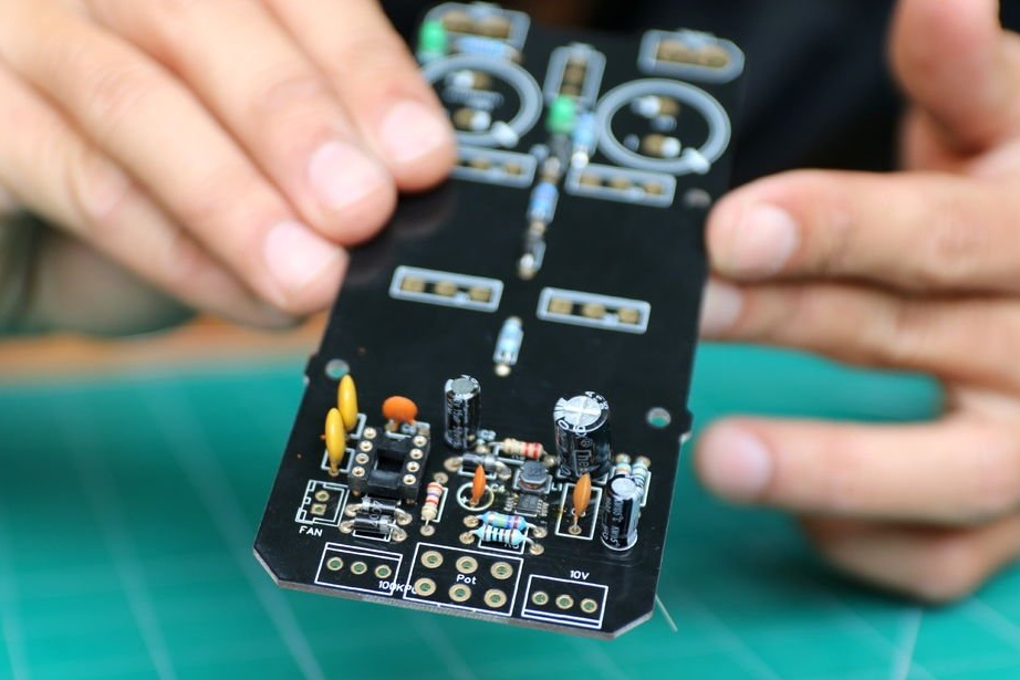
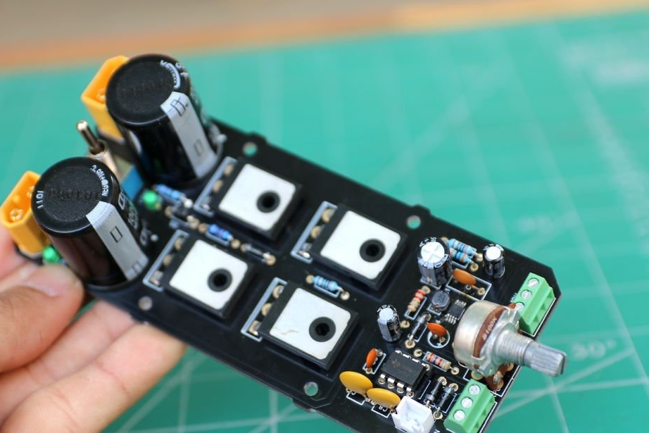
After assembling the board, it's time to set the 555 timer with a notch in the right direction.
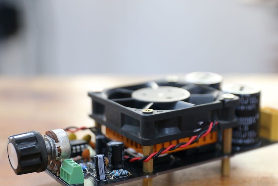
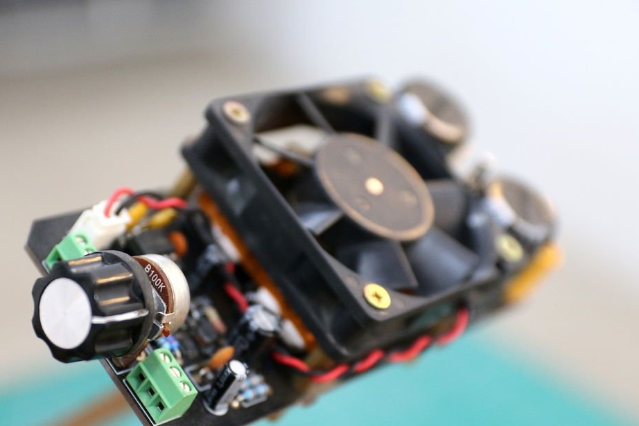
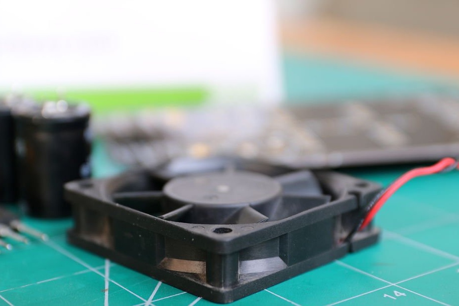
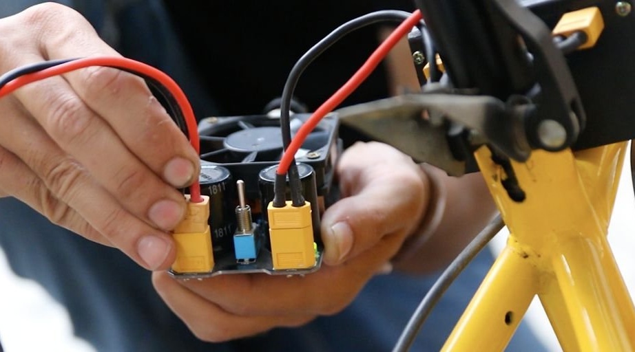
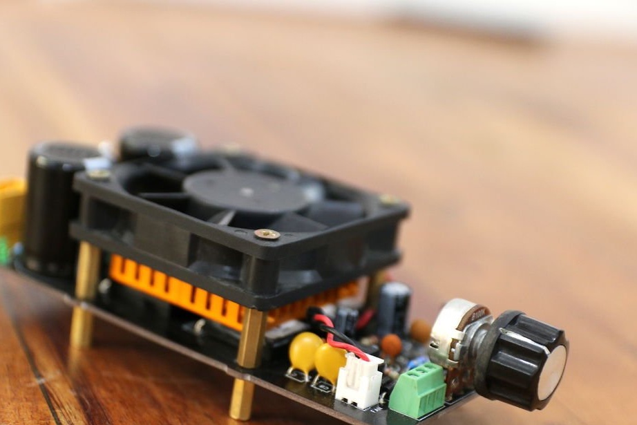
Step 6: Cooling
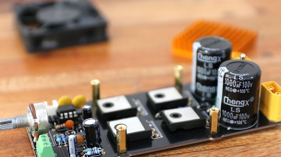
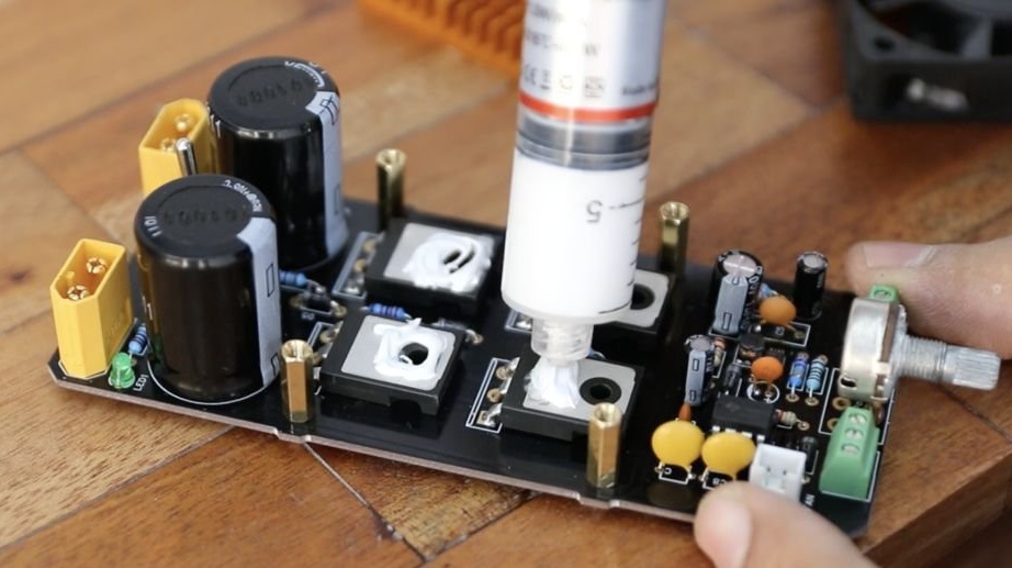
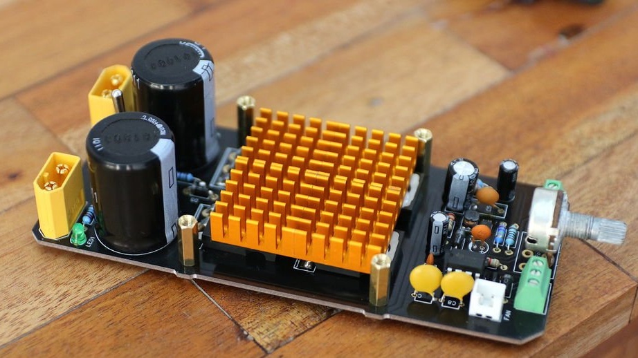
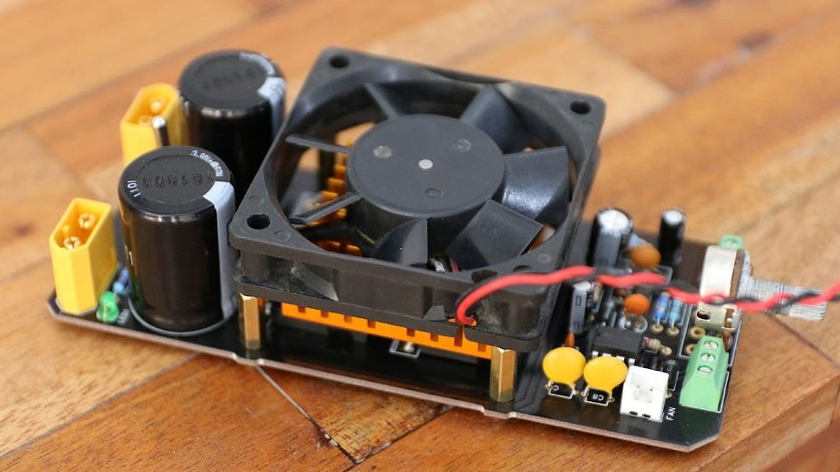
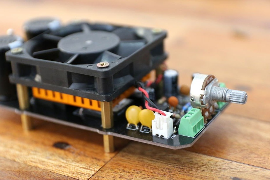
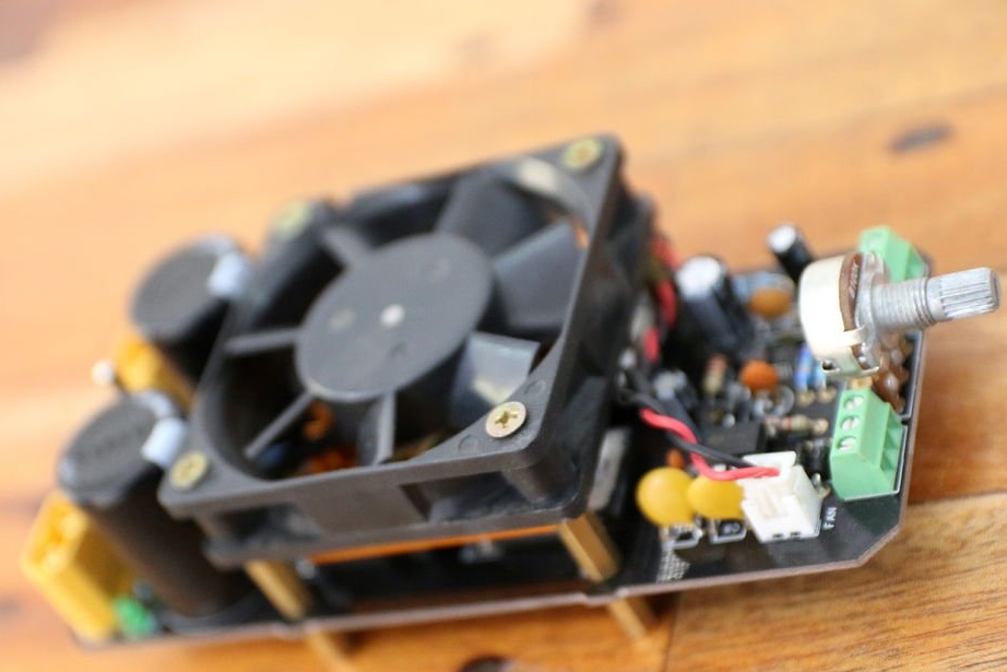
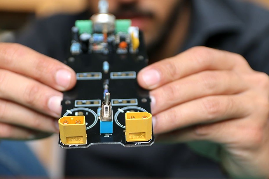
With so much energy to deal with, it’s obvious that the board will heat up. Therefore, in order to cope with excess heat, it is necessary to bend MOSFETs and install a 12 V fan with a switch between radiators.
After that, the PWM speed controller is ready for operation.
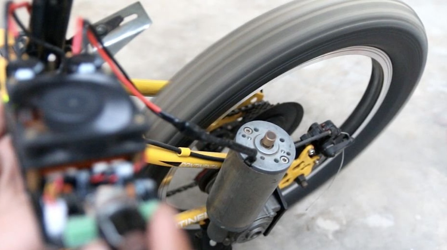
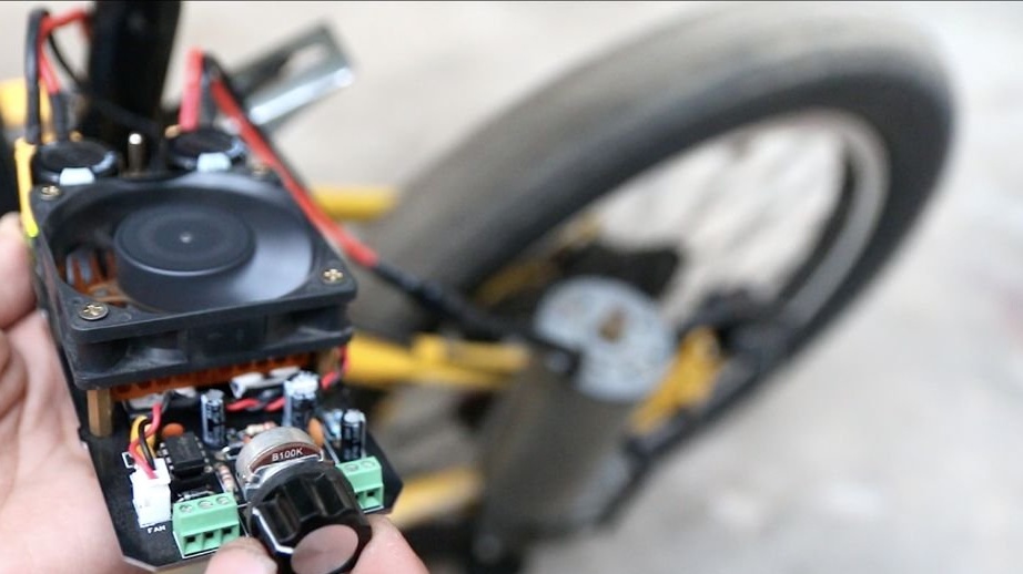
Step 7: testing the controller
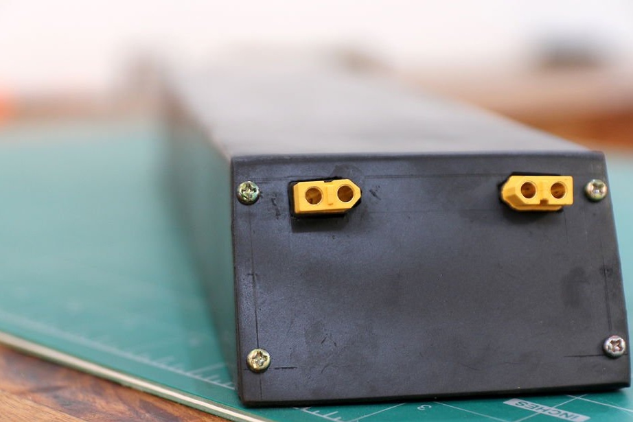
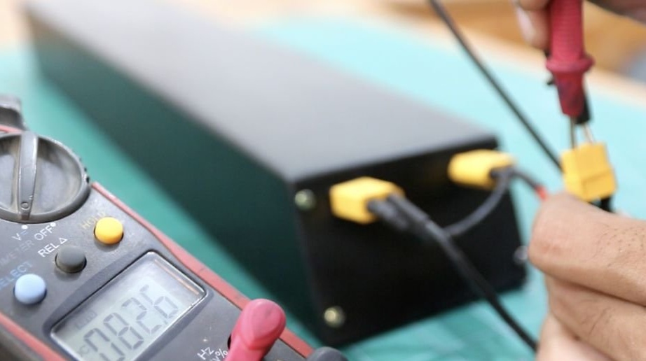
To test the controller, an 84 V battery for an electric bicycle, which was made by the master earlier, will be used. The controller is temporarily connected to the battery and the motor, which is attached to bike to drive the rear wheel.
After switching the switch, the controller turns on and the fan blows air through the MOSFETs. When the potentiometer rotates clockwise, the engine starts to rotate and gradually increases speed, in proportion to the rotation of the handle.
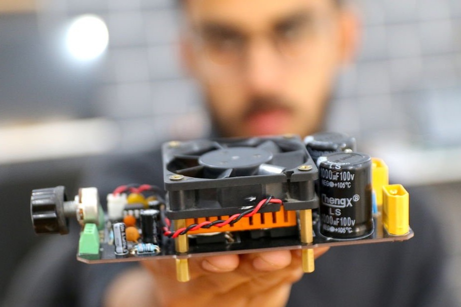
Step 8: Final Results

The speed controller is ready and it exceeded all the expectations of the master in relation to its capabilities. The controller works easily with a 84 V battery and smoothly controls the speed of the engine.
But in order to test this speed controller under load, the master needs to complete his bicycle project and mount all the components together.
You can also watch a video on the assembly of this controller: