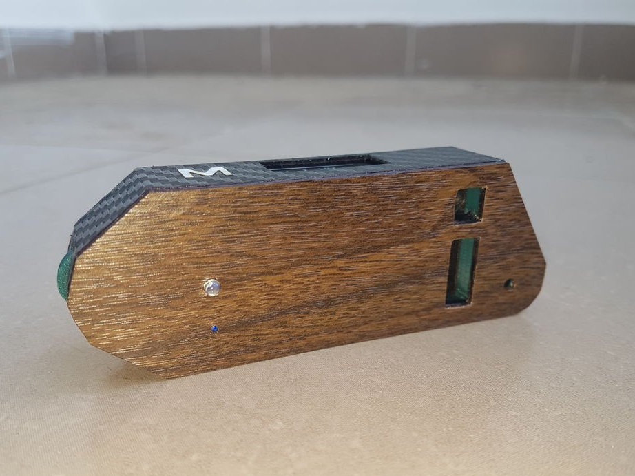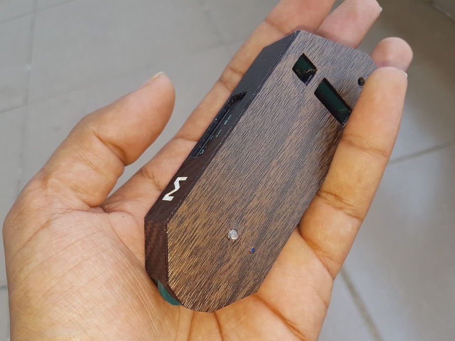
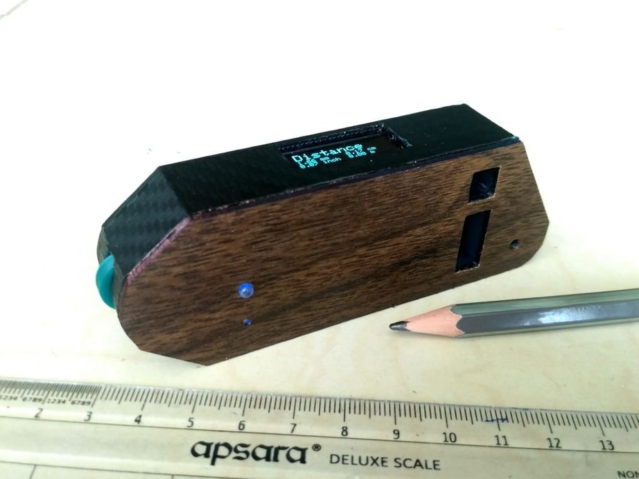

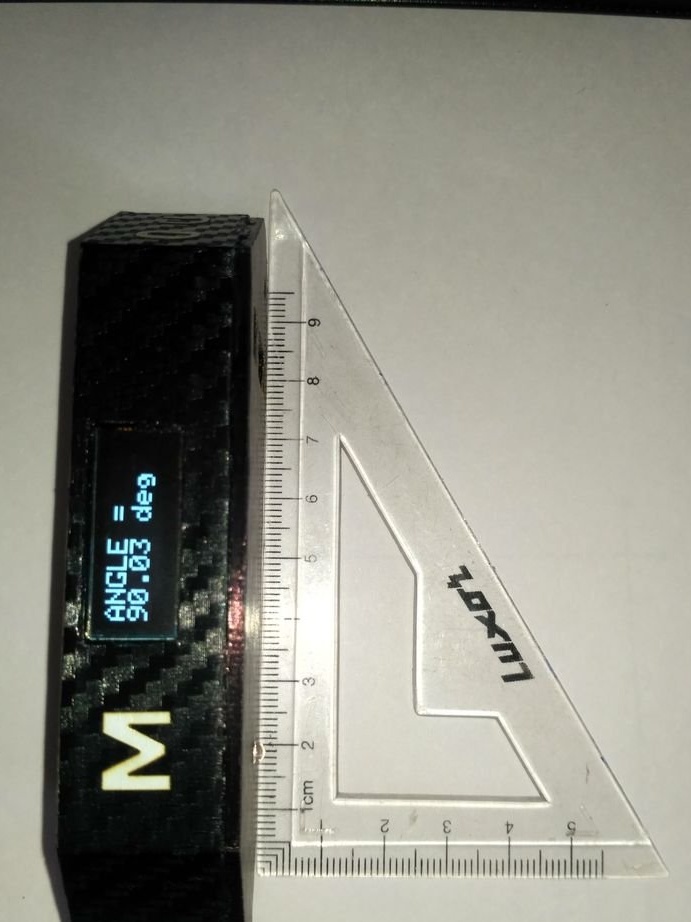

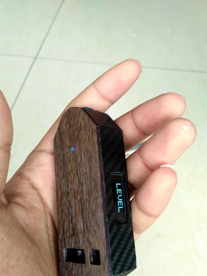
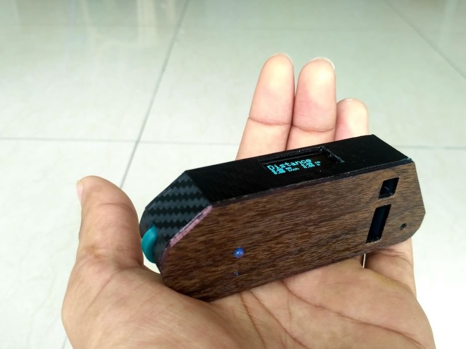
The wizard created a device that works like a digital level + ruler + protractor + tape measure. The device is small enough to fit in a pocket, and its battery is easily charged using a phone charger.
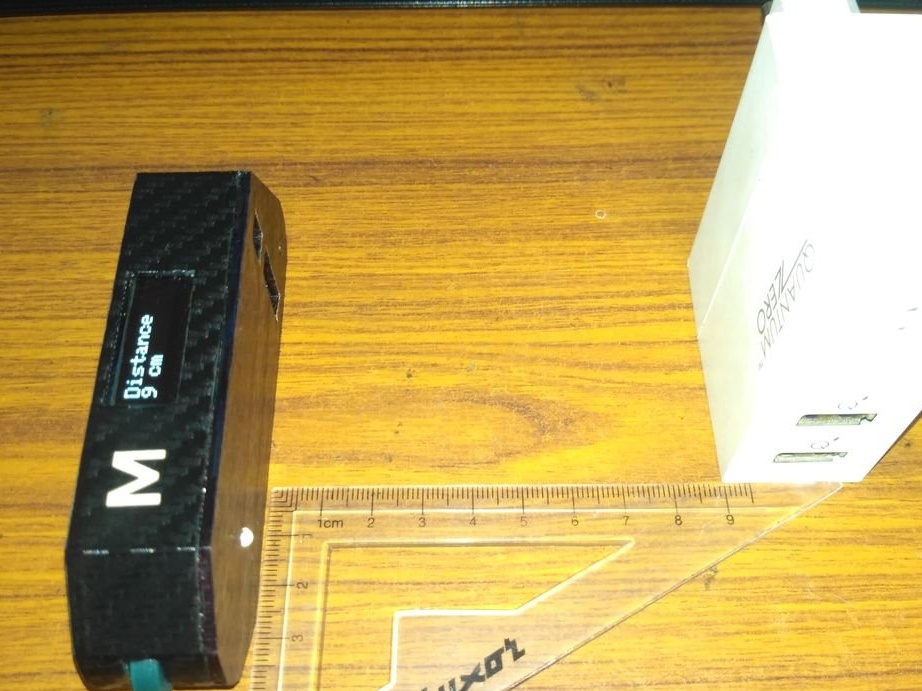
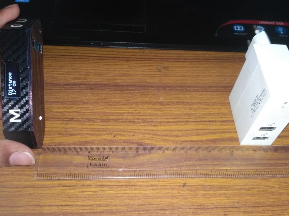
This device uses an accelerometer and a gyroscope sensor to accurately measure level and angle, an IR sensor for non-contact measurement of linear length from 4 to 30 cm, a sensor with a wheel that can be rolled along a curved surface or a curved line to measure the length of an object.
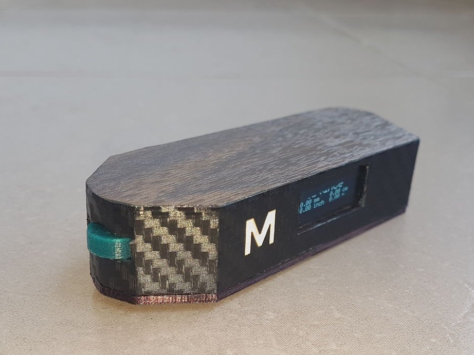
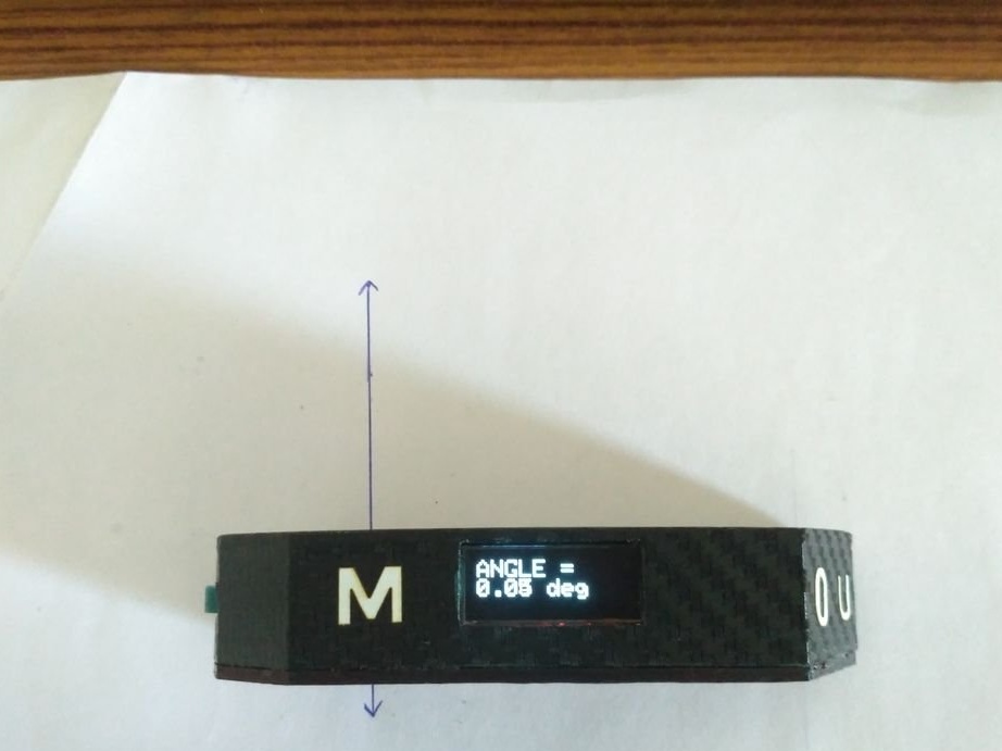
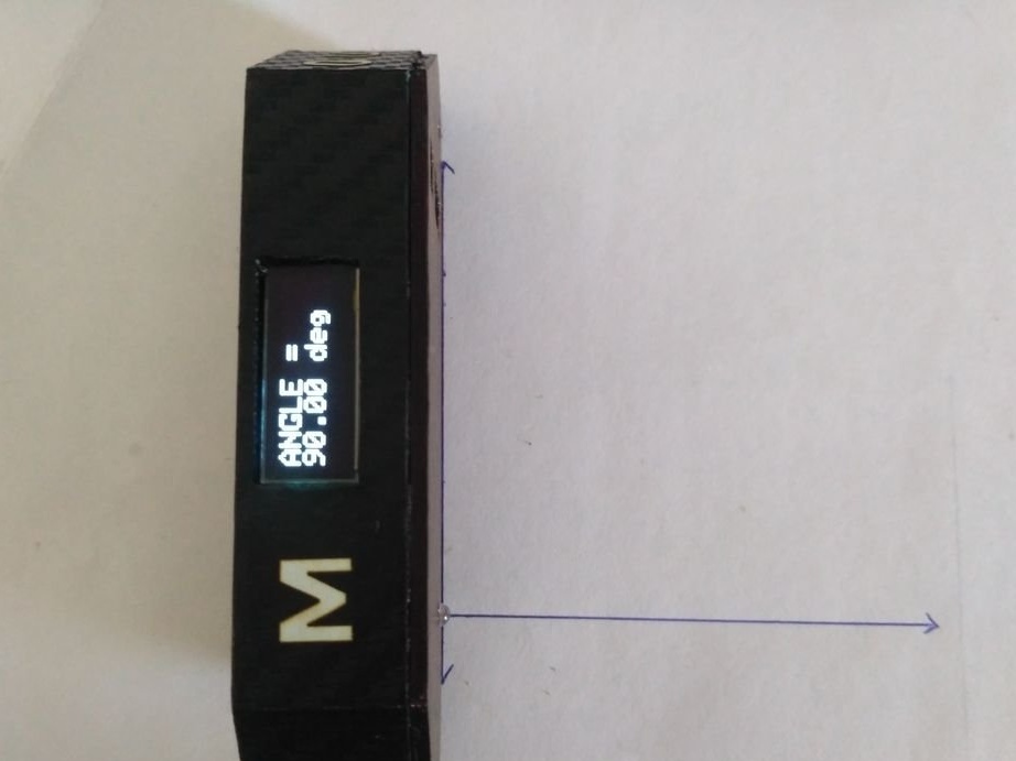
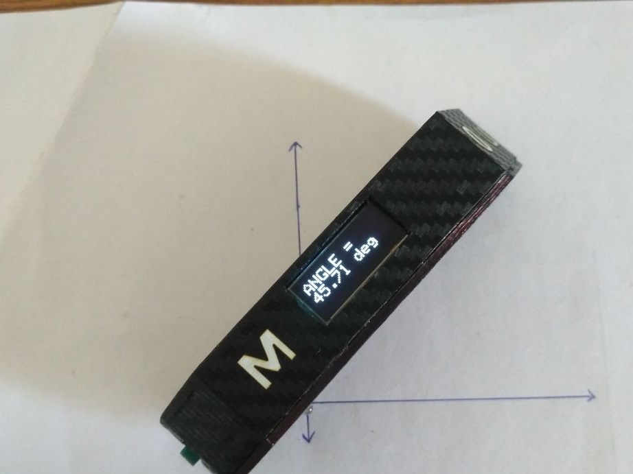
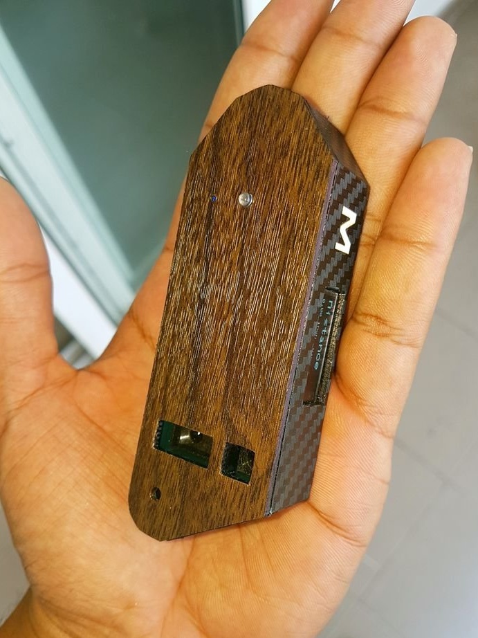
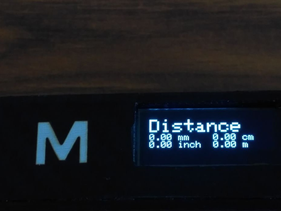
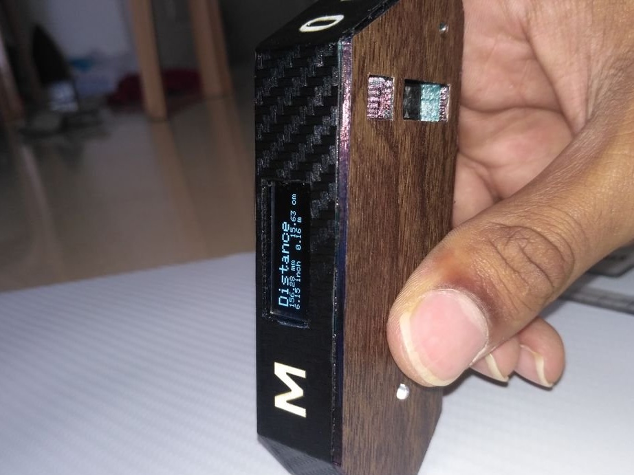
Navigation through the modes and functions of the device is carried out using the touch buttons, designated as M (mode), U (unit) and 0 (zero).
M - choice between different types of measurements
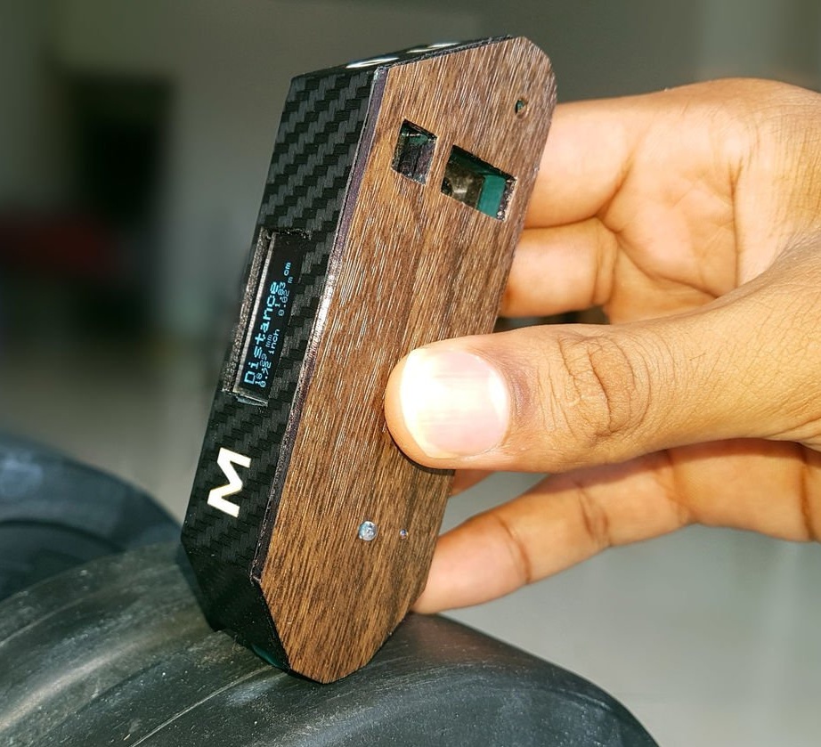
U - to choose between units of measurement mm, cm, inches and meter
0 - Reset measured values to 0 after measuring distance or angle.
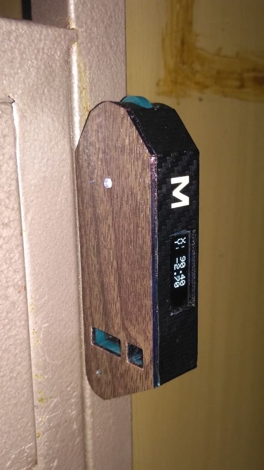
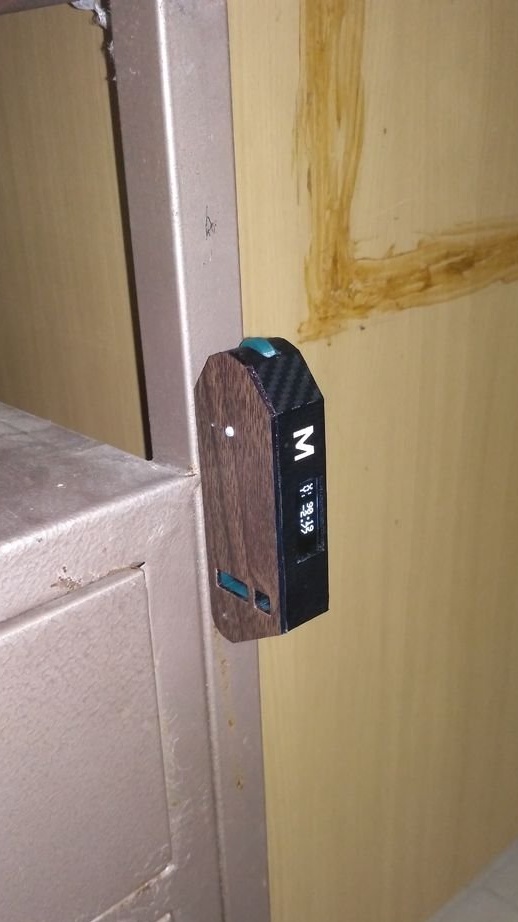
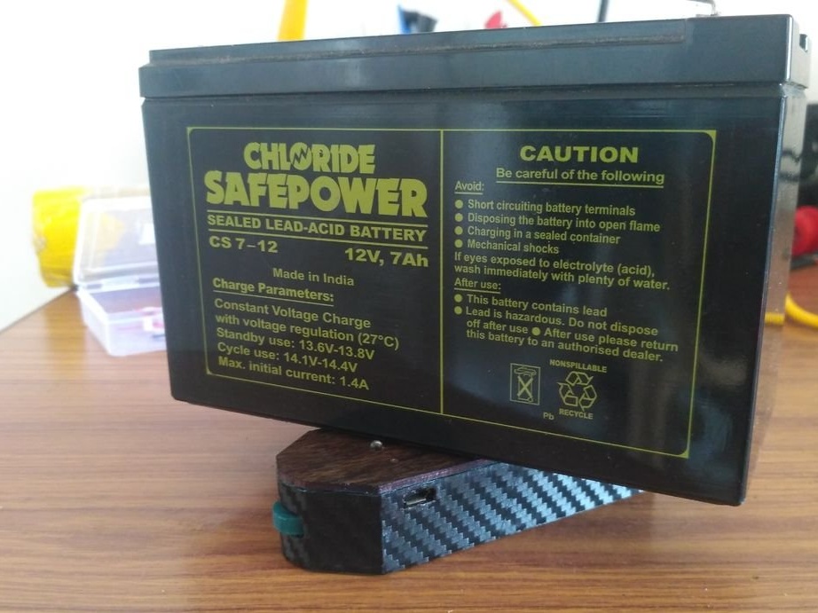
The device has a neodymium magnet built into its base so that it does not slip and does not slide off the metal surface being measured.
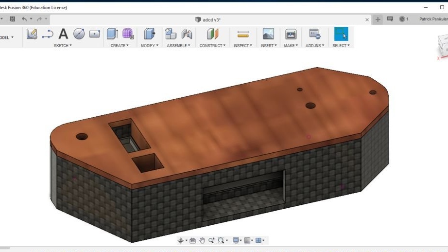
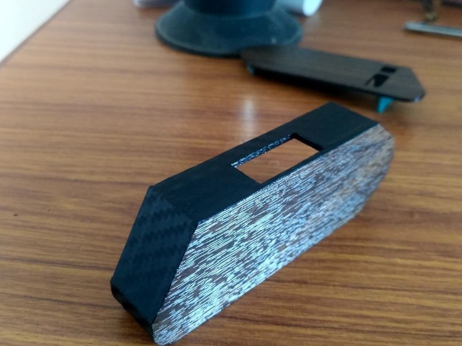
The case is designed to make the device as compact as possible.
Let's watch a video with examples of how the device works.
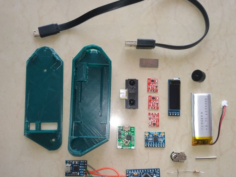
Tools and materials:
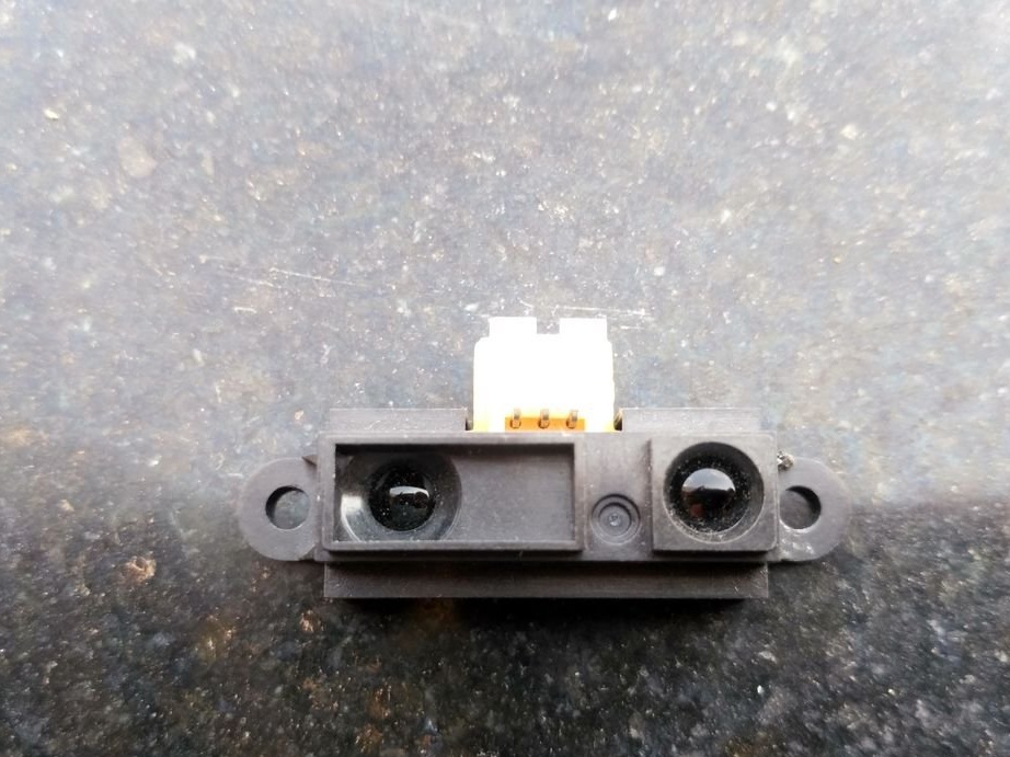
-IR distance sensor Sharp GP2Y0A41SK0F;
- Module MPU6050 accelerometer / gyroscope;
-Charge module;
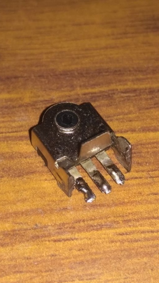
Encoder
-128 X 32 OLED display;
-Arduino pro mini ATMEGA328 5 V / 16 MHz;
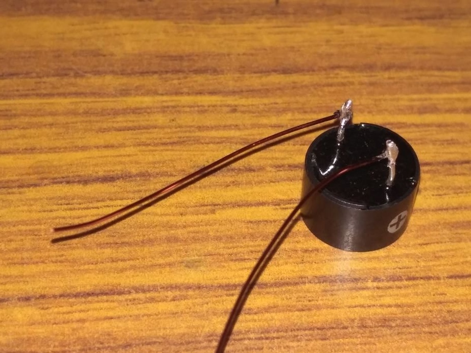
-12 mm buzzer;
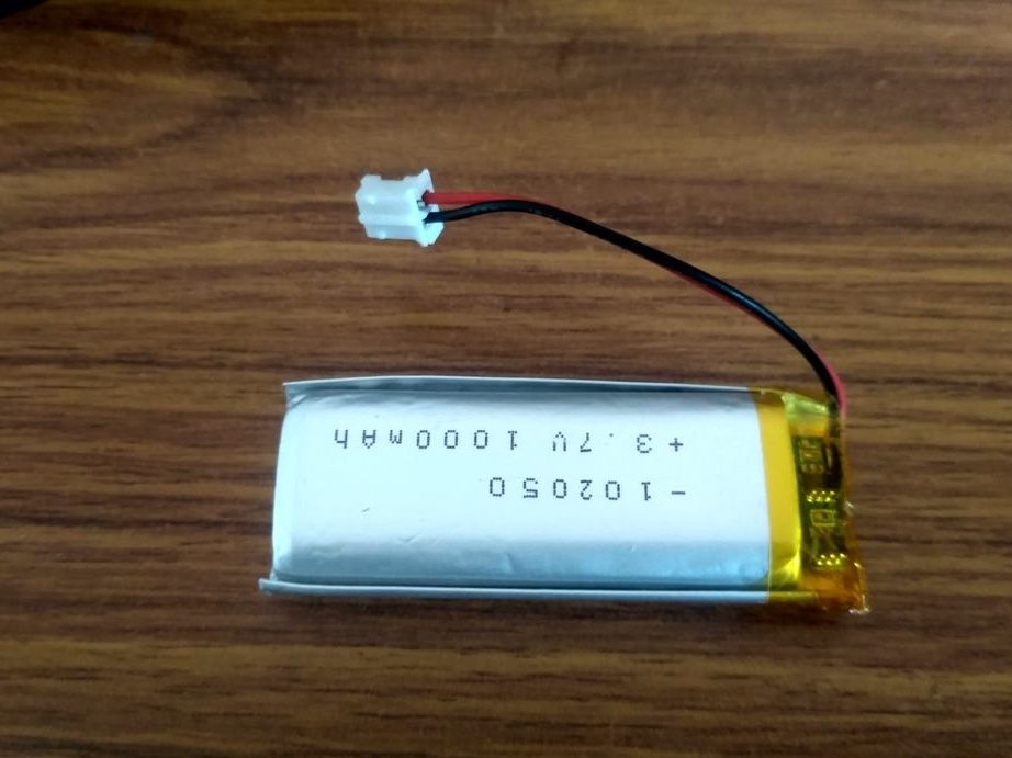
-3.7 V, 1000 mAh lithium polymer battery;
- TTP223 touch button module - 3 pcs.;
- Neodymium magnet 20x10x2 mm;
-Converter interface CP2102;
Enamelled copper wire;
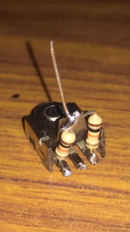
-Resistors 10K - 2 pcs;
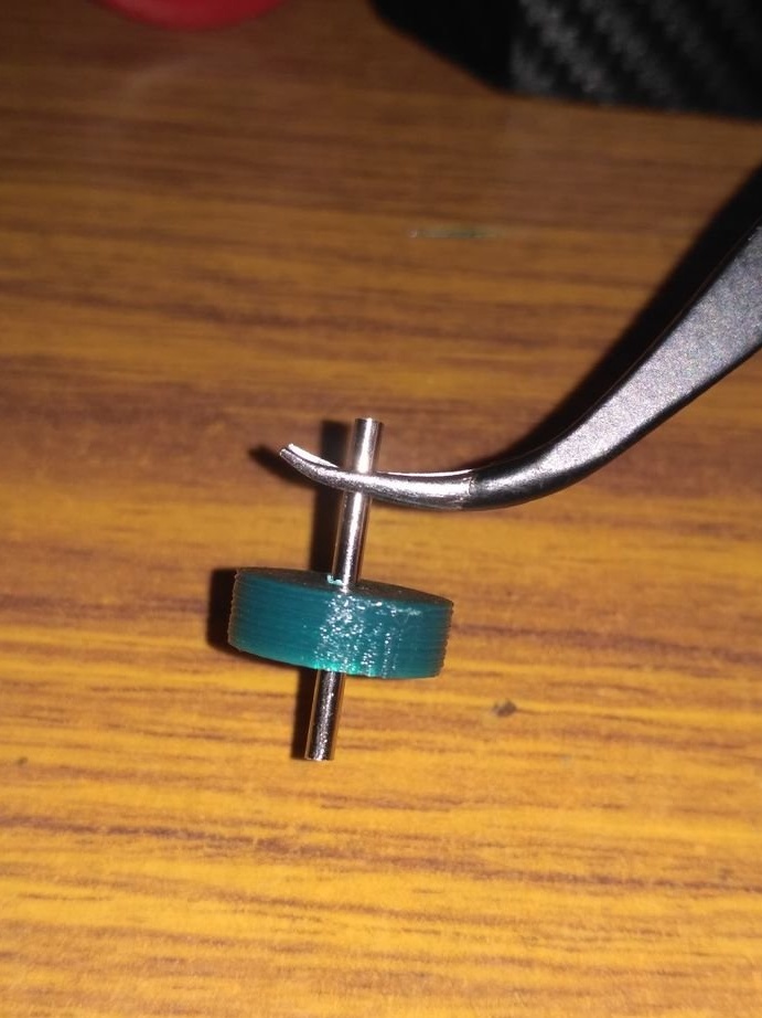
- Steel rod 19 mm long with a diameter of 2 mm;
-Light-emitting diode;
-Vinyl film;
- Micro USB cable;
-Scissors;
-Knife;
-Tweezers;
-Glue gun;
-Super glue;
-Soldering accessories;
-Laser cutter;
- 3D printer;
-Nippers;
-Sandpaper;
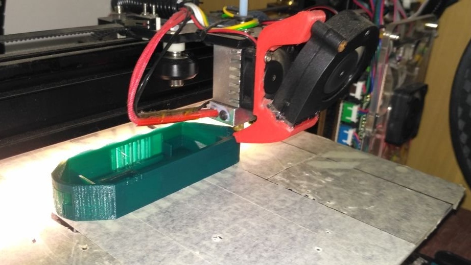
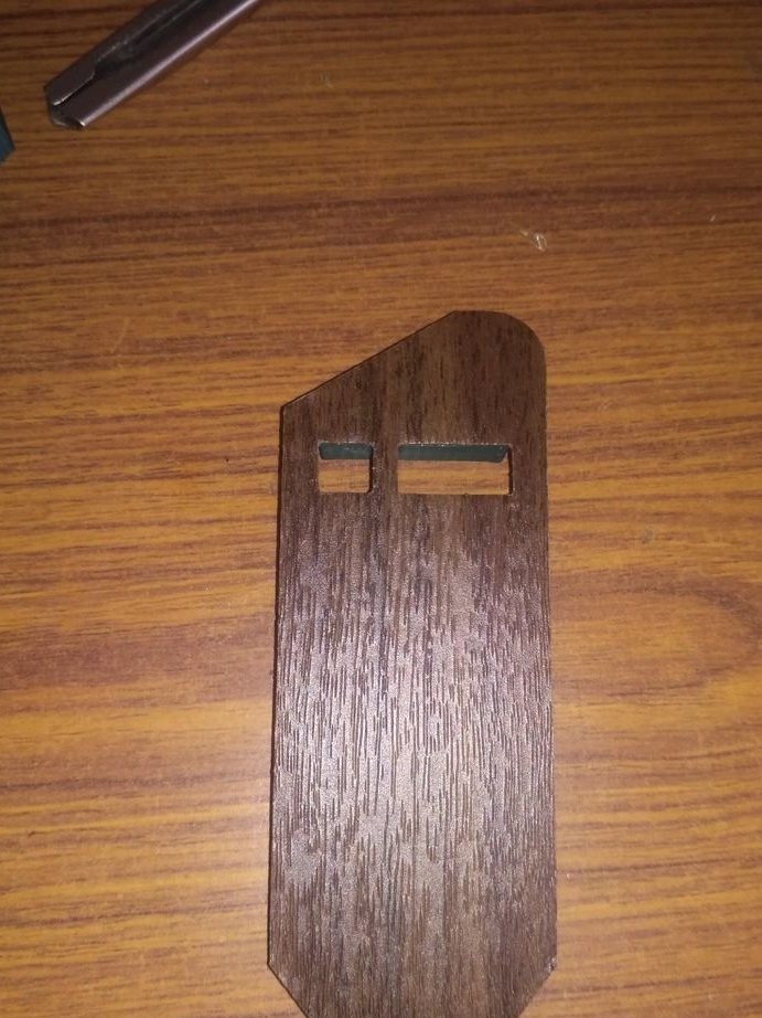
Step One: The Case
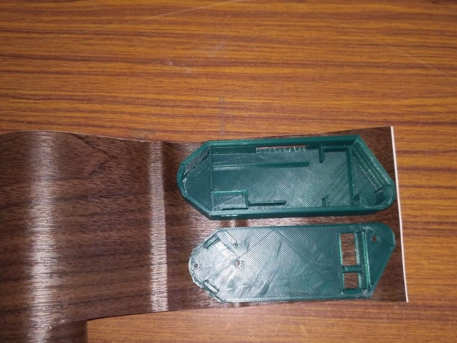
First, the wizard prints a case on a 3D printer. Files for printing can be downloaded below.
BODY.stl
Lid.stl
wheel.stl
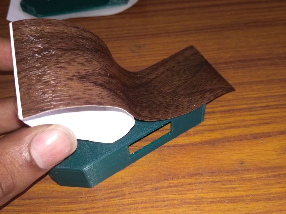
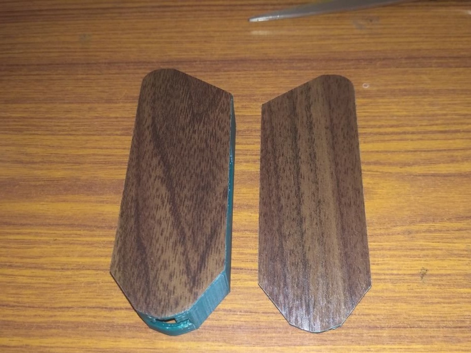
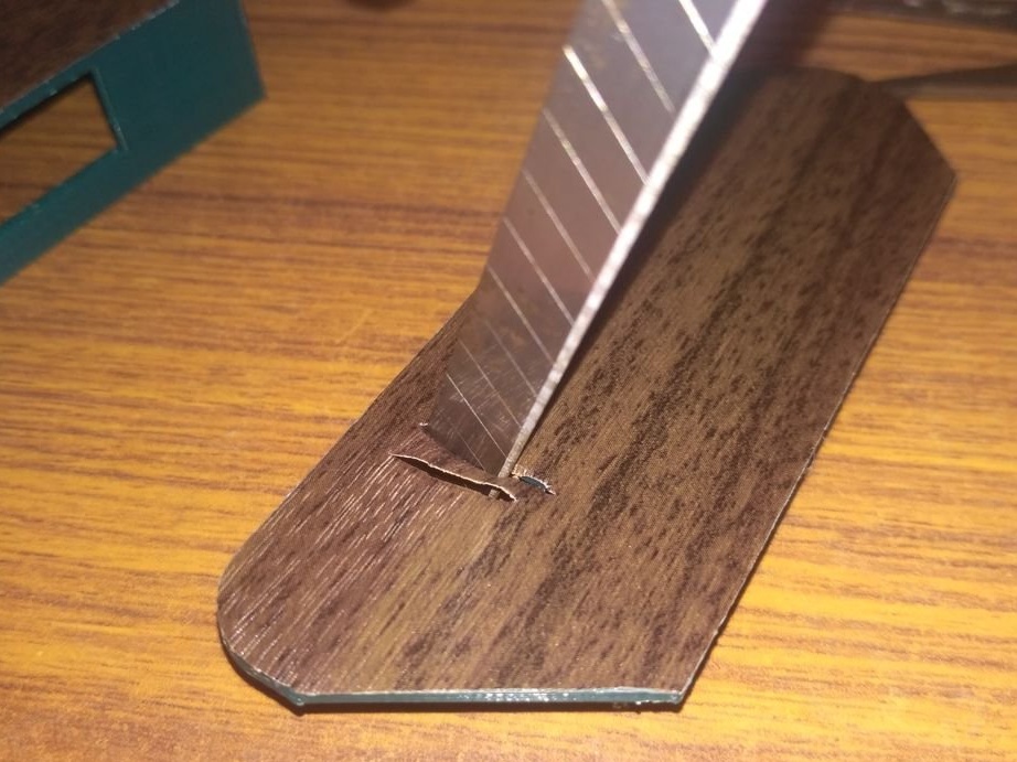
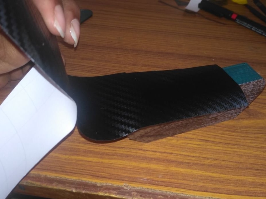
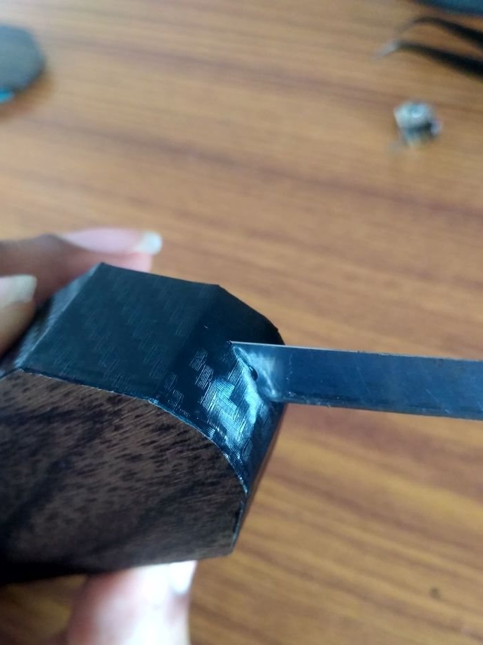
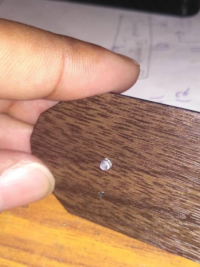
It glues the case with vinyl film, previously sanding its surface.

Step Two: Scheme
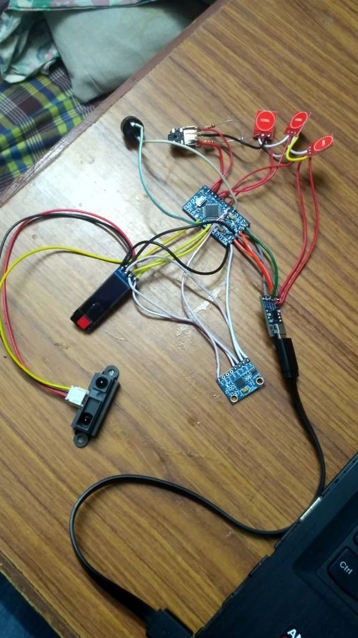
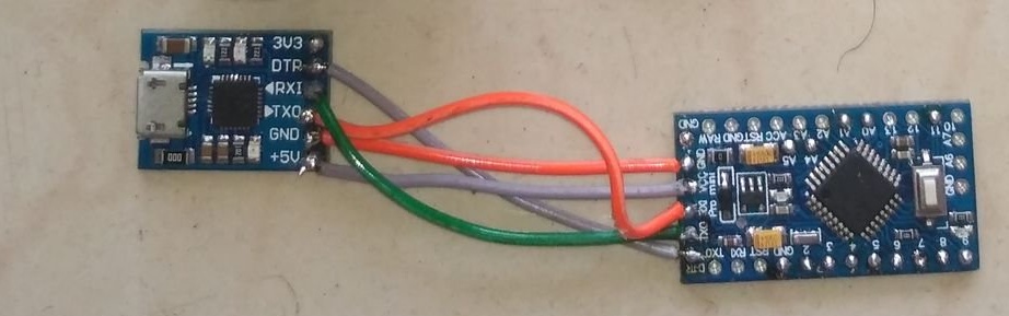
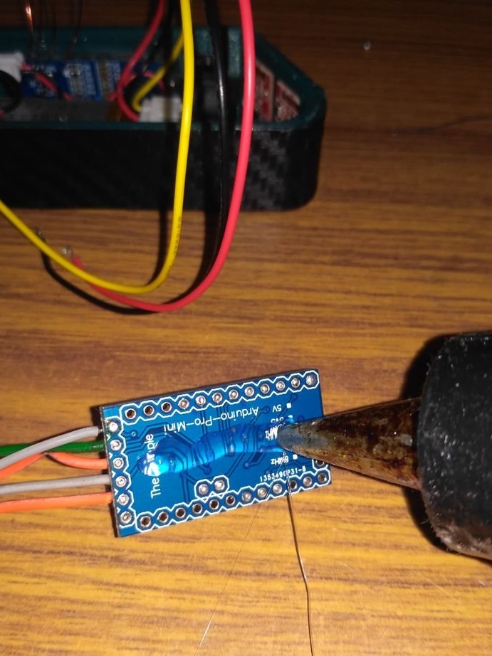
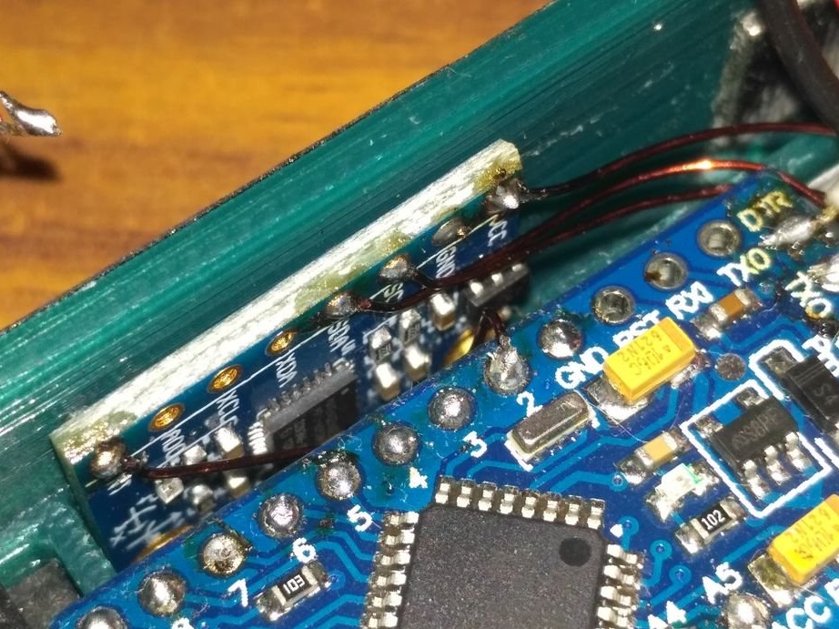
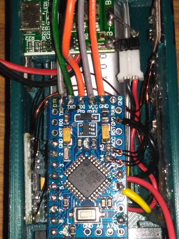
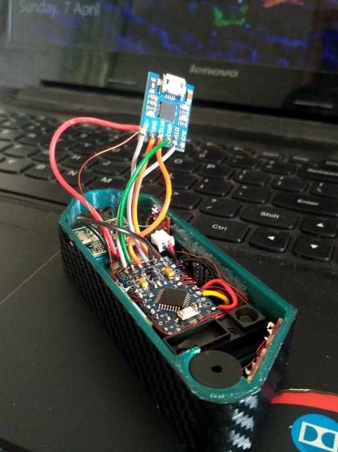
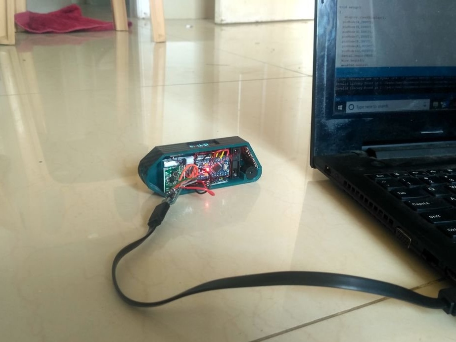
Unlike Arduino nano, pro mini cannot be programmed directly by connecting a USB cable. Therefore, you first need to connect an external USB to the pro mini converter in order to program it. The first photo shows how these connections should be made.
Vcc - 5V
GND - GND
RXI - TXD
TXD - RXI
DTR - DTR
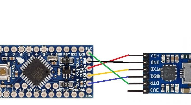
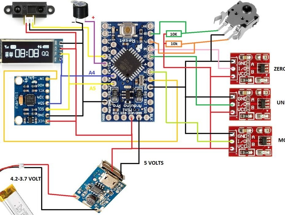
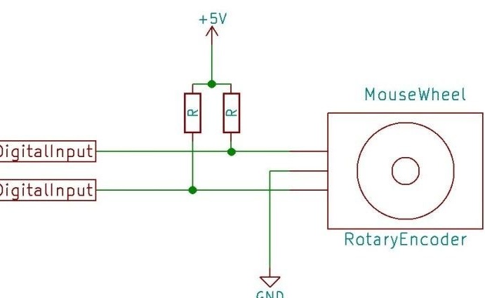
The 2nd image shows the complete circuit diagram of this project.
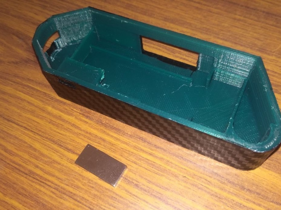
Step Three: Magnet
Glues the magnet to the body.
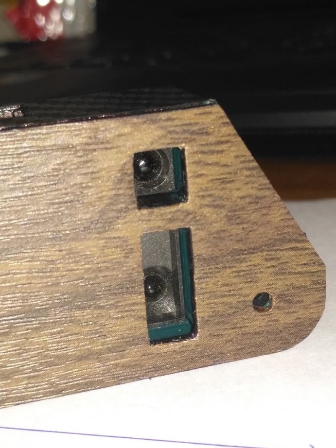
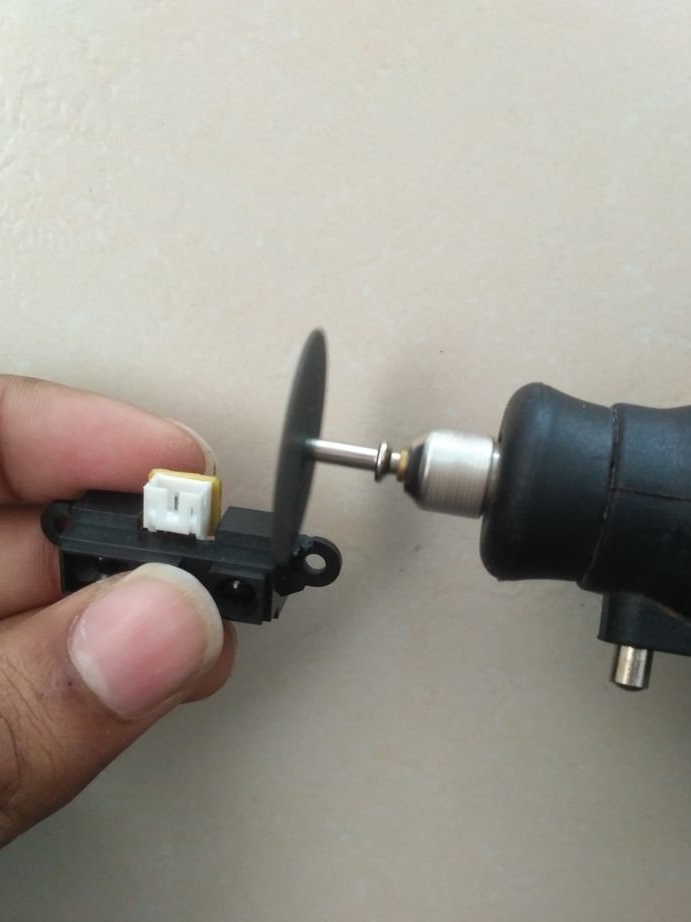
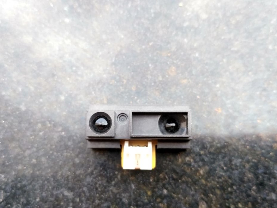
Step Four: Sensor Alignment
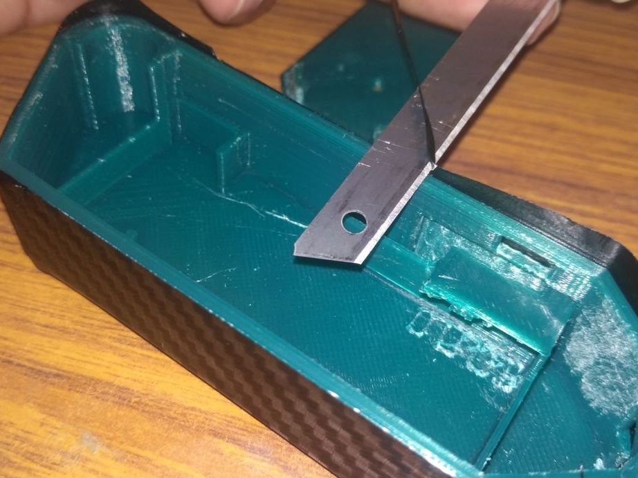
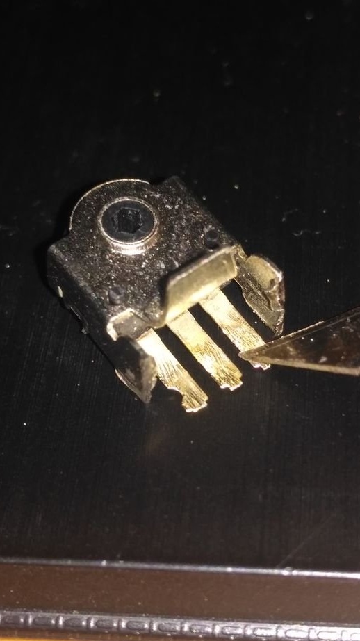
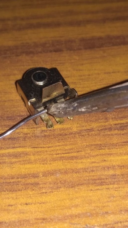
To reduce the size, the IR sensor and encoder are cut off.
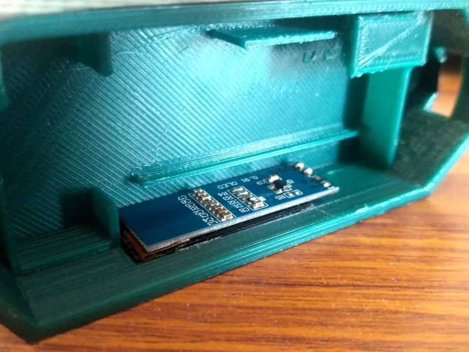
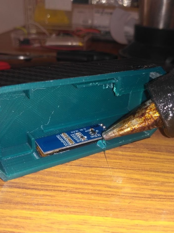
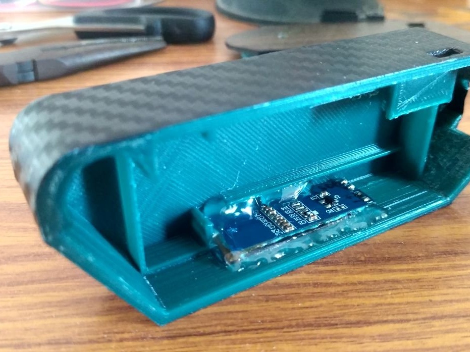
Step Five: Display
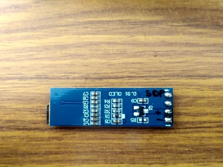
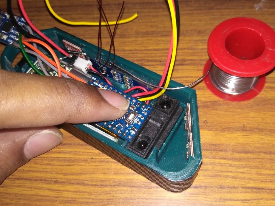
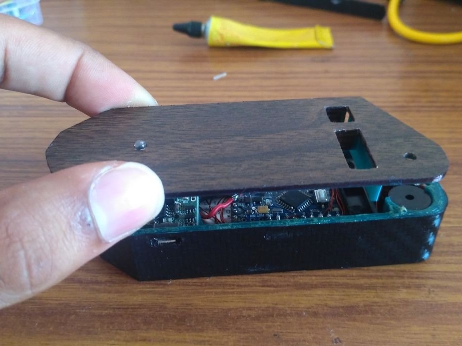
Marks the names of the contacts on the back of the OLED display so that you can subsequently make the correct connections. Sets the OLED display to the correct position, as shown in the second figure. Fixes the display with hot glue.
Step Six: Modules
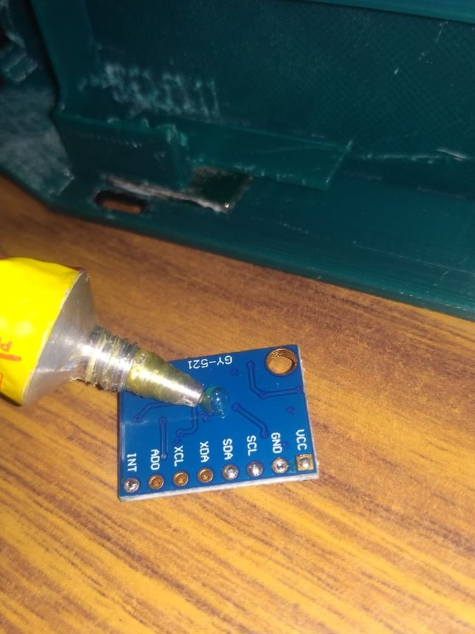
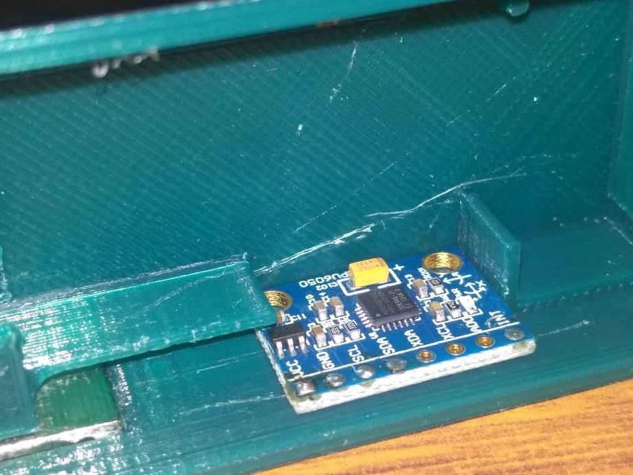
Glues the sensor module and MPU6050.
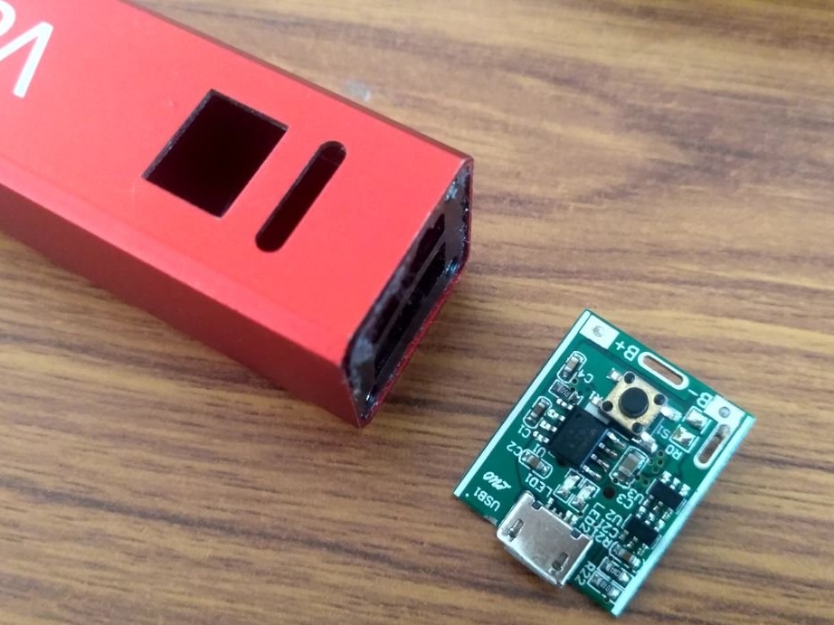
Seventh step: charging module and battery
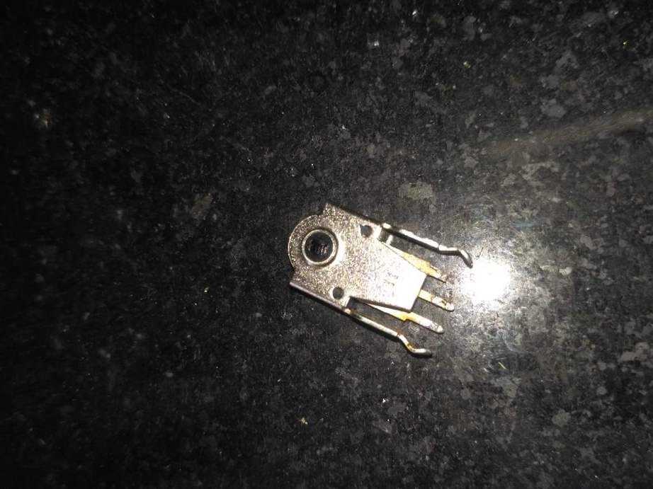
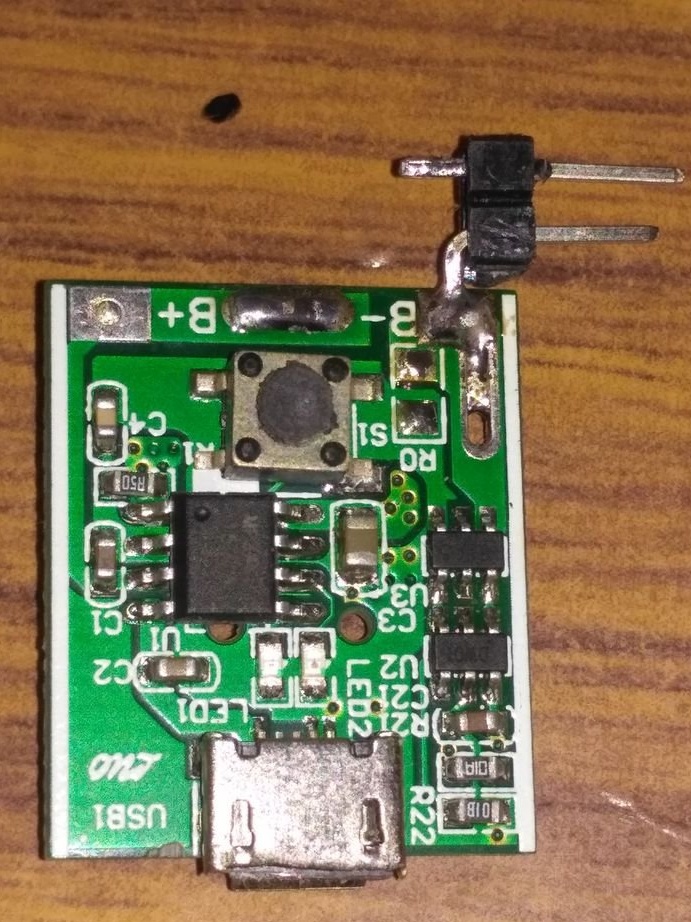
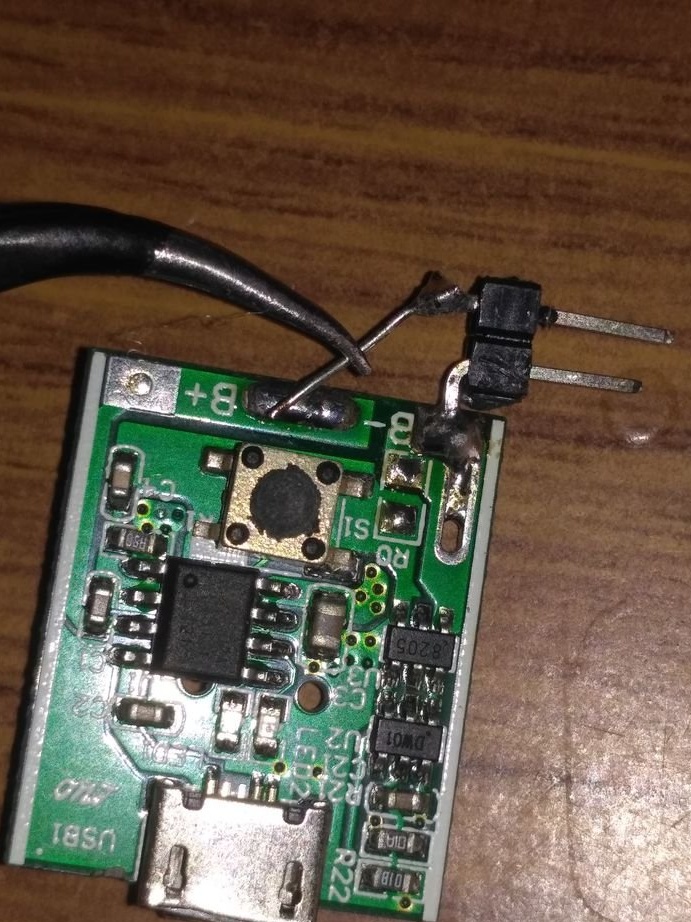
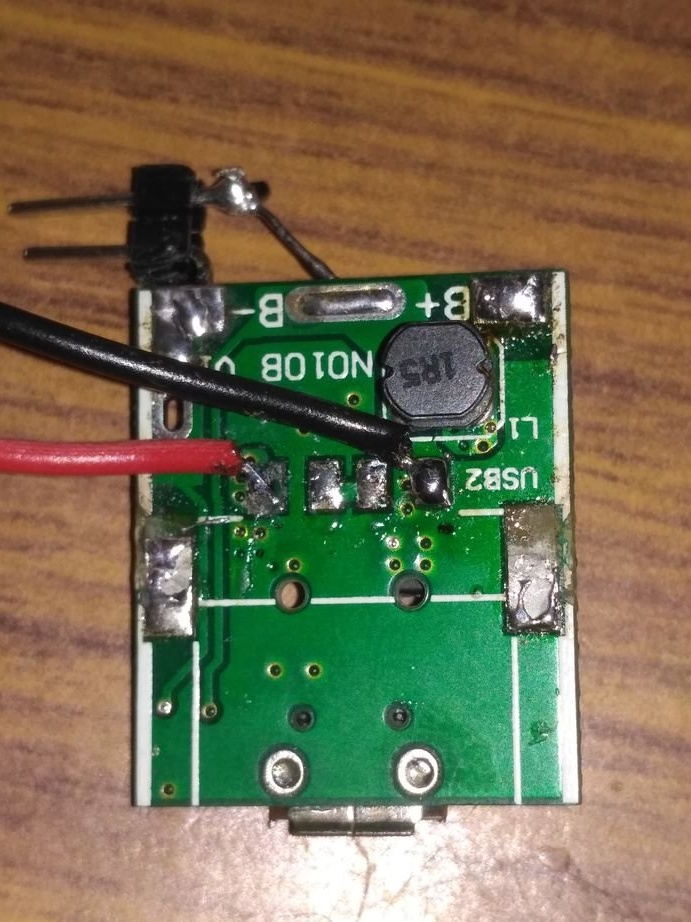
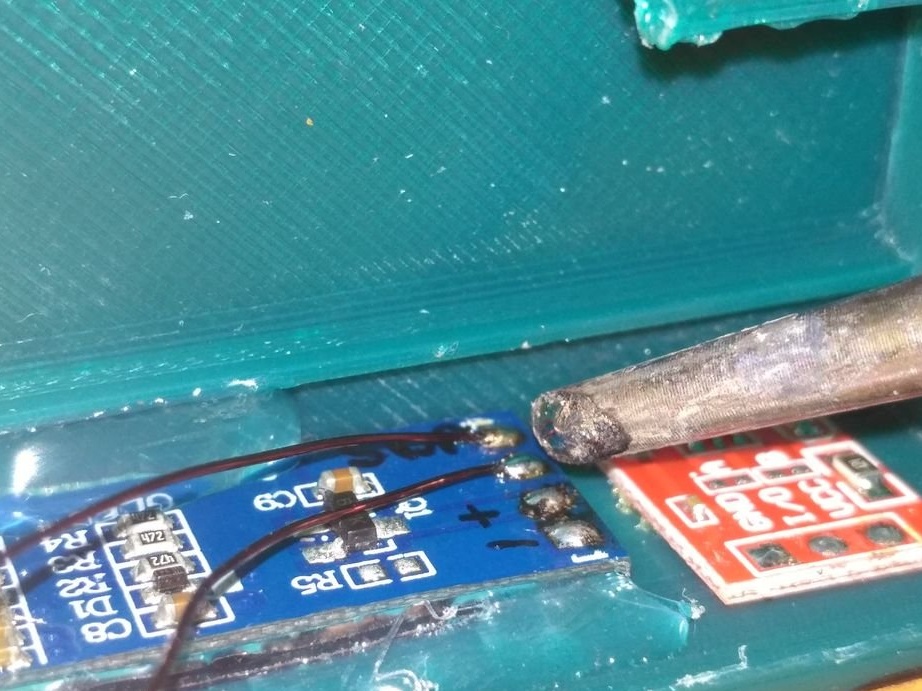
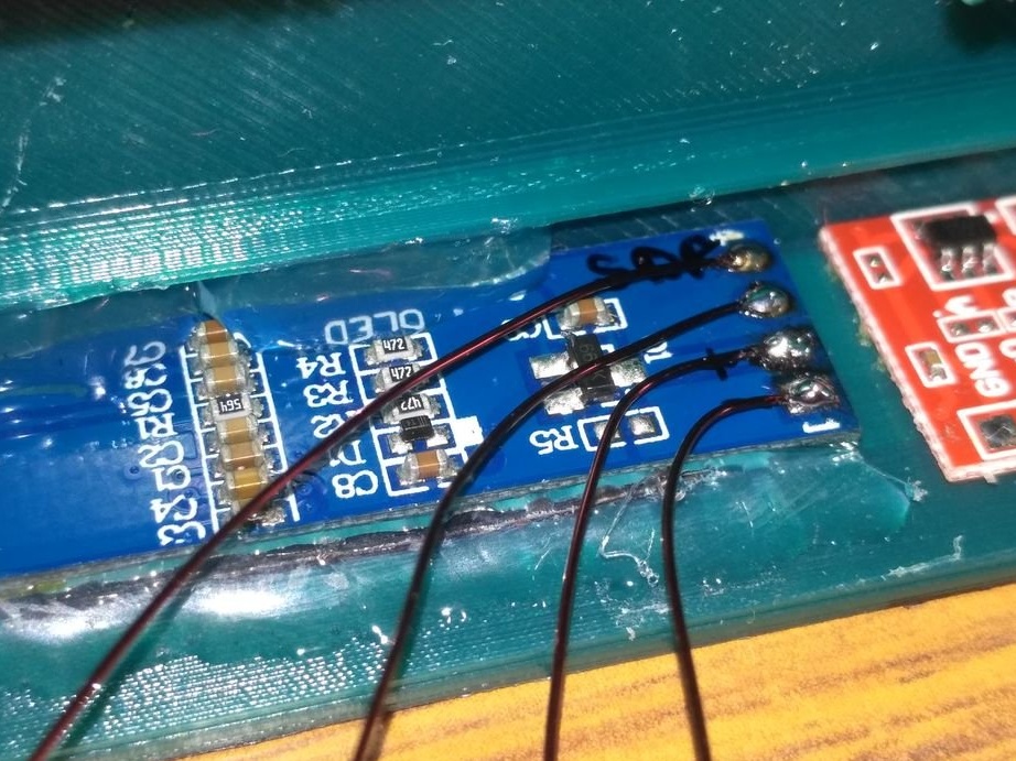
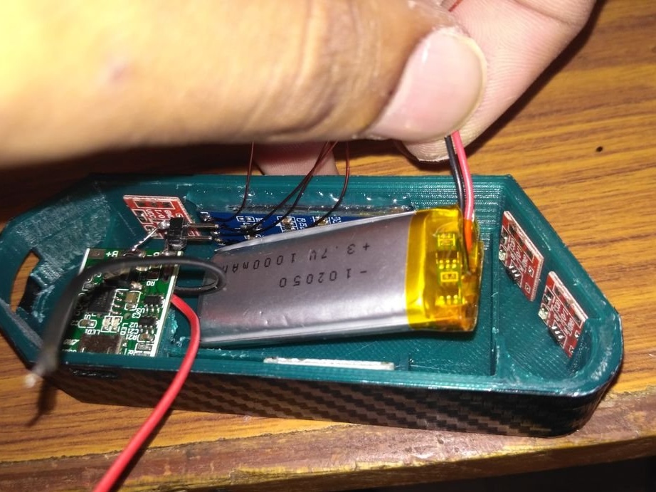
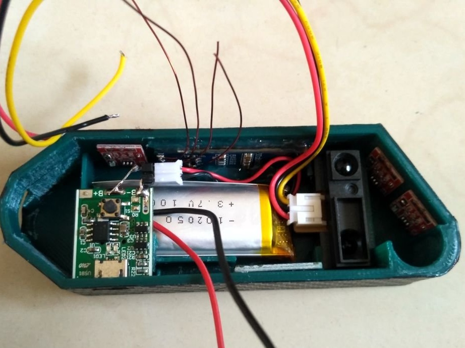
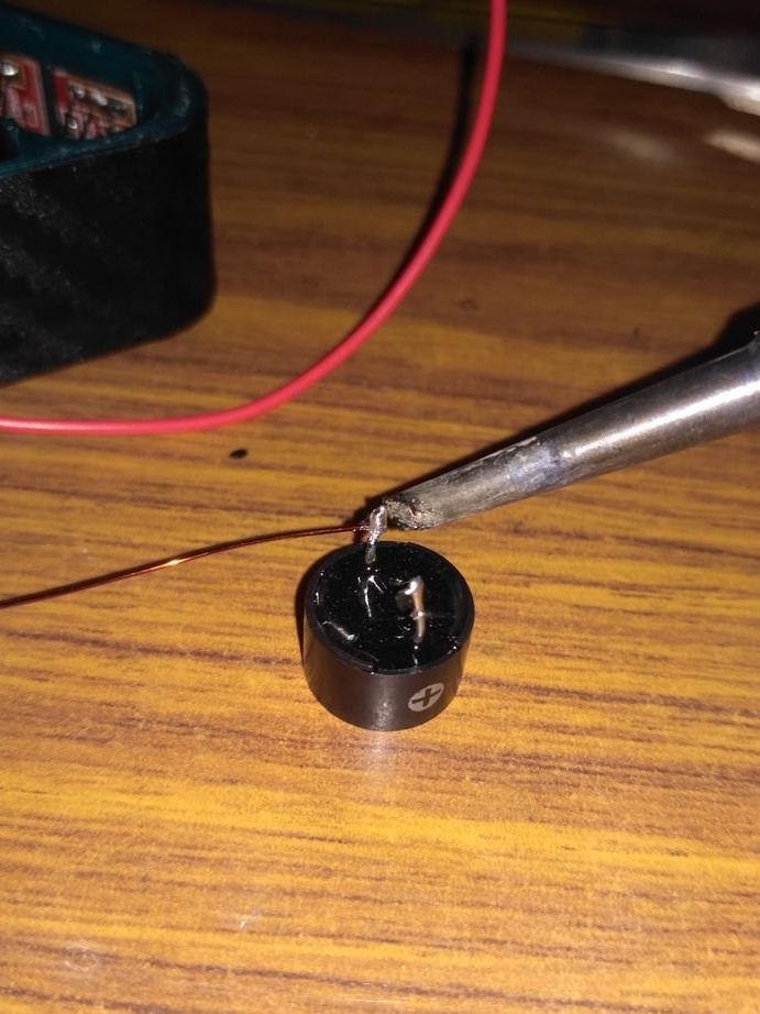
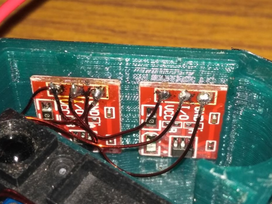
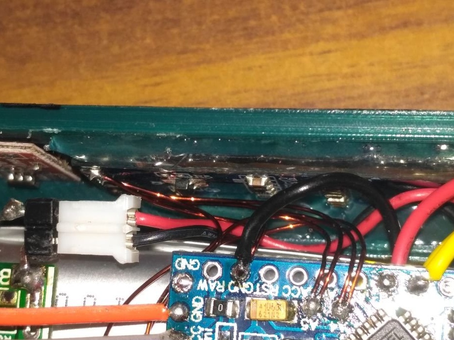
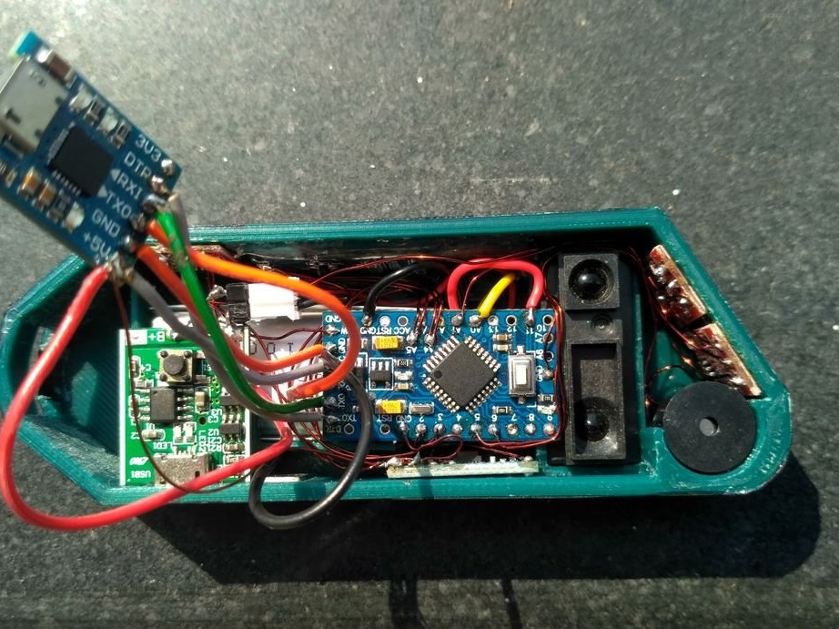
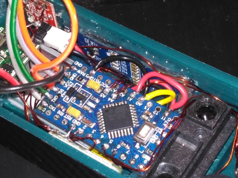
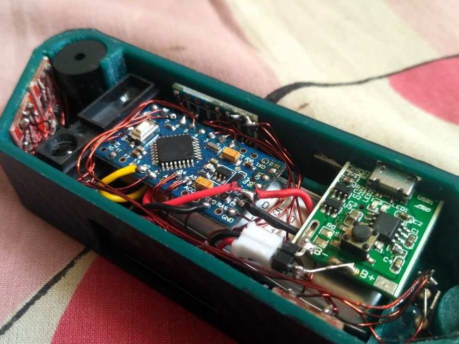
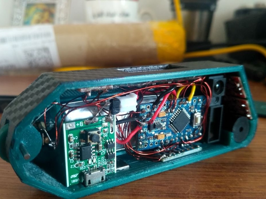
This module has both a battery protection circuit and a boost converter 5 V, 1 A. It also has an on / off button that can be used as a power switch. The USB socket port on the module was removed using a soldering iron, and two wires were soldered to the + 5 V terminals and ground, as shown in the 4th photo.
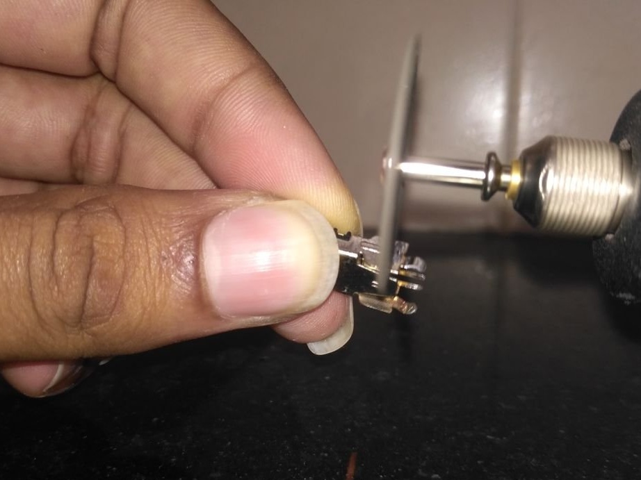
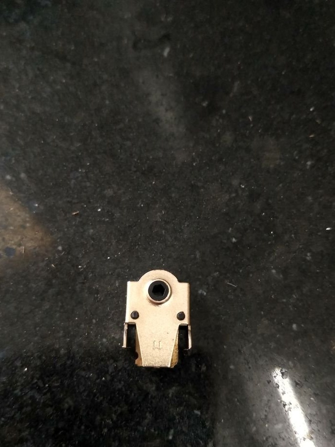
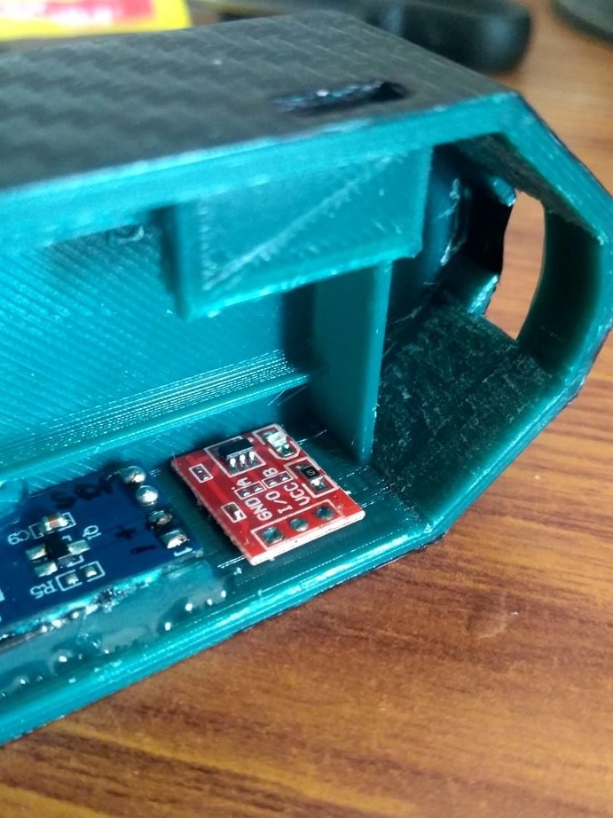
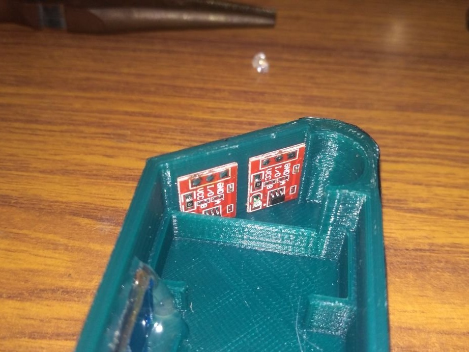
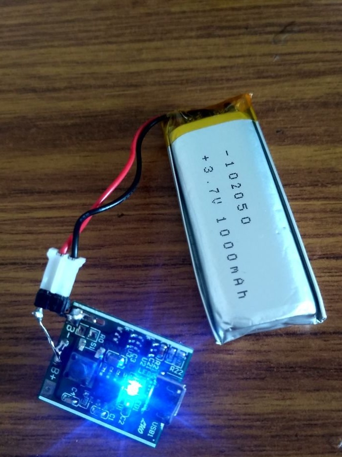
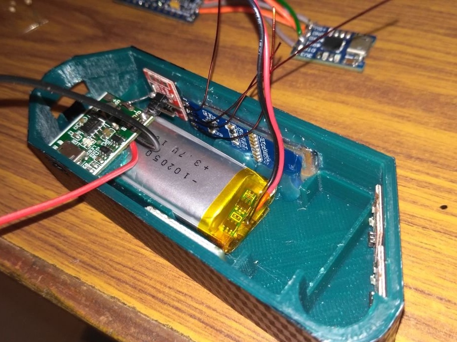
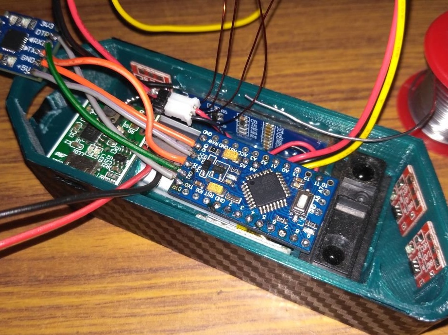
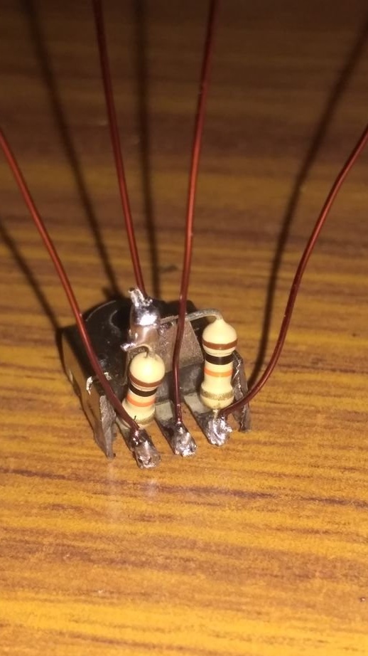
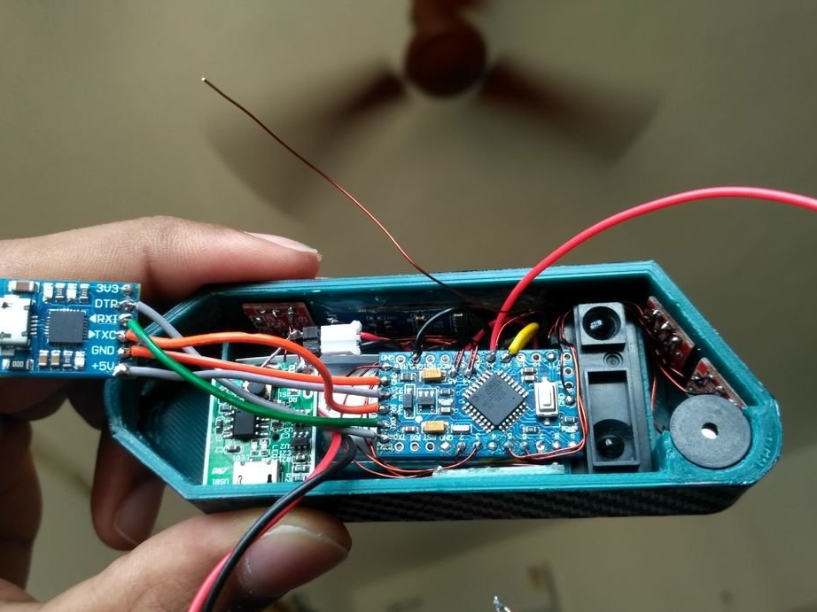
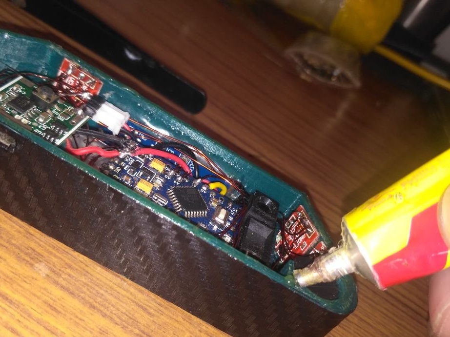
Next, you need to solder the 2 plug connectors to B + and B-, as shown in the first two photos, and then check whether the module works with the battery.
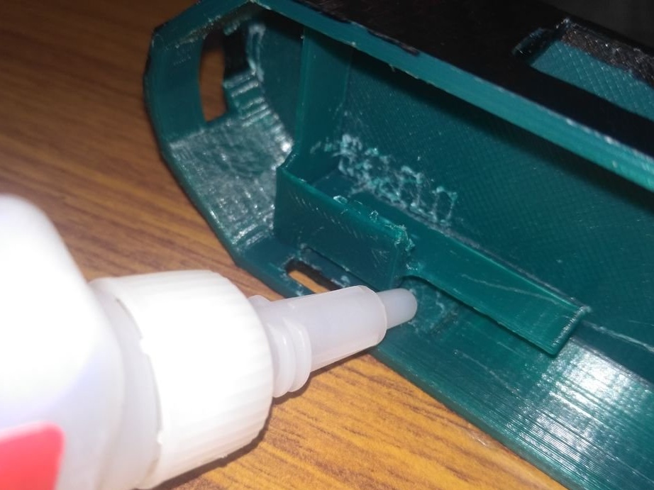
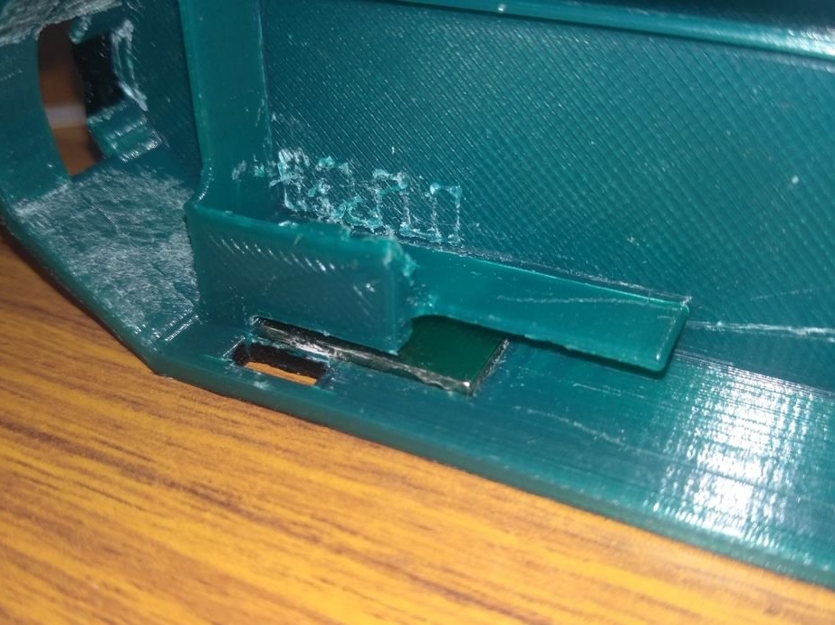
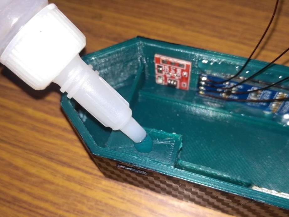
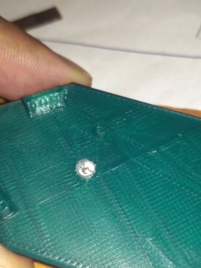
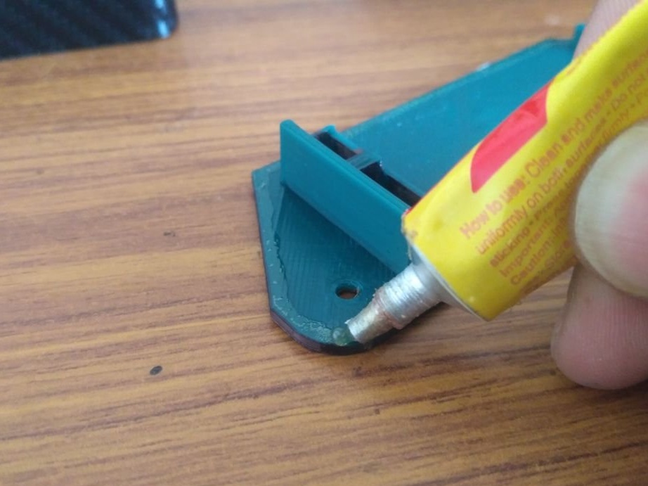
Now you need to apply glue to the platform provided for the module, and carefully place the module, making sure that the charging port and hole are installed exactly in the holes.
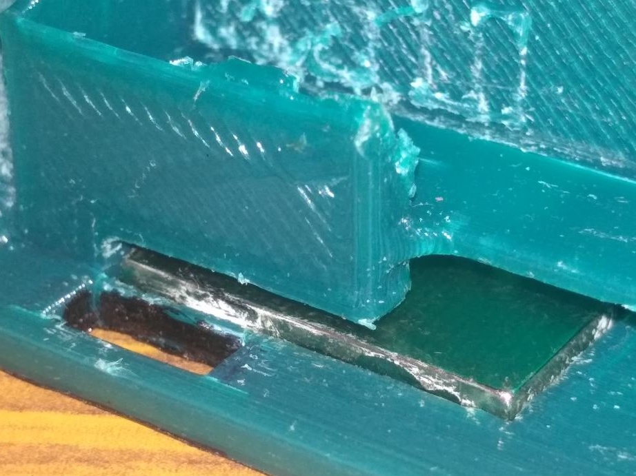
Step Eight: Installing the Battery and IR Sensor
Solder wires to the display pins. Installs the battery and IR sensor.
Step Nine: Buzzer and Charging Module
According to the scheme, it mounts the charging module and the buzzer.
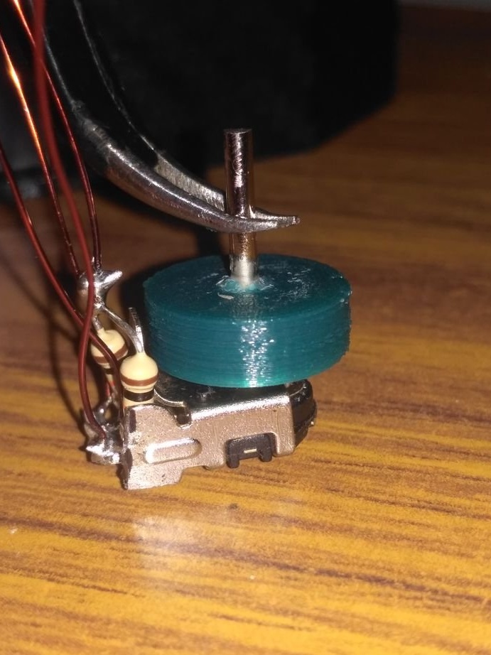
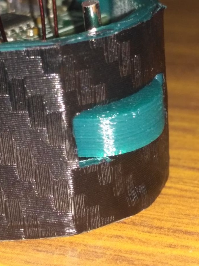
Step Ten: Encoder
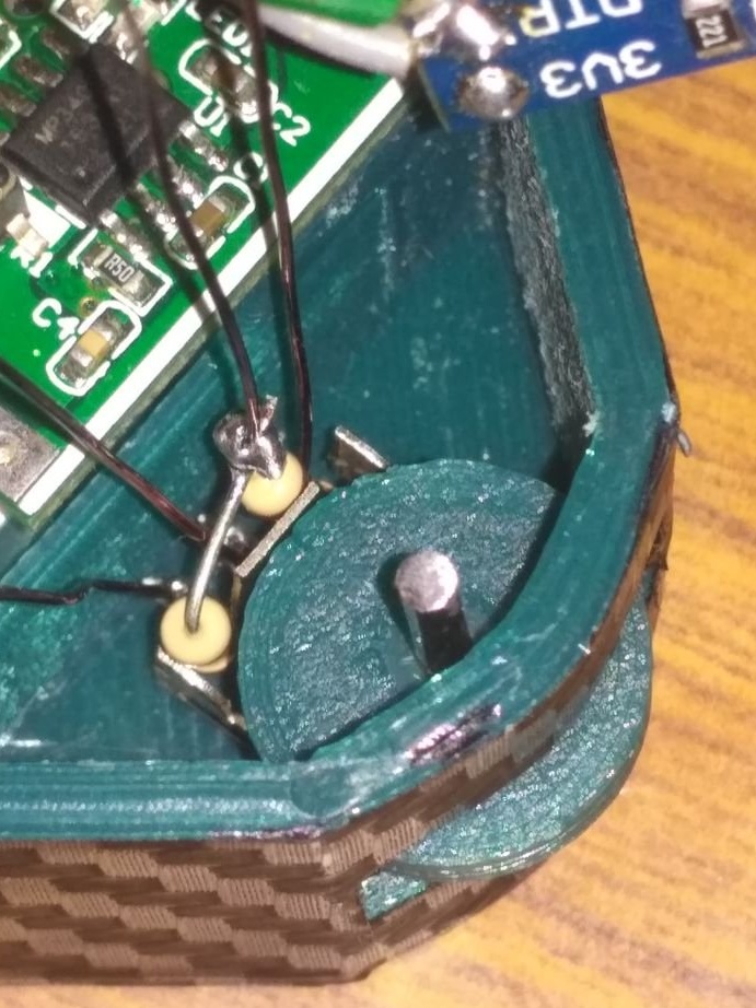
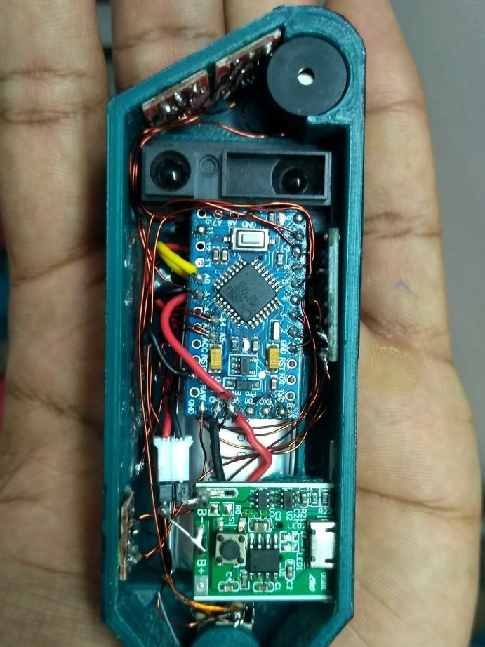
According to the scheme mounts the encoder. Inserts the steel axis into the encoder and wheel. It uses super glue to fix the axle and wheel. Installs an encoder with a wheel inside the housing.
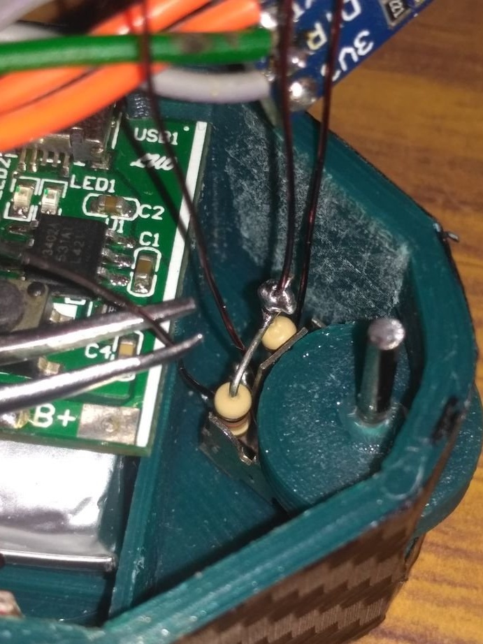
Step Eleven: Installation
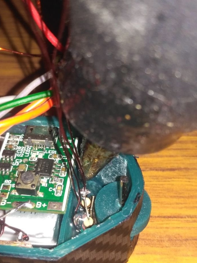
Fixes sensor modules. According to the circuit mounts the wires. During installation, it is necessary to ensure that the wires do not fall under the wheel and do not cover the IR sensor overview.

Step Twelve: Download Code
Loads code and libraries.
final_code.ino
Adafruit_SSD1306-master.zip
Adafruit-GFX-Library-master.zip
SharpIR-master.zip
Step Thirteen: Calibration
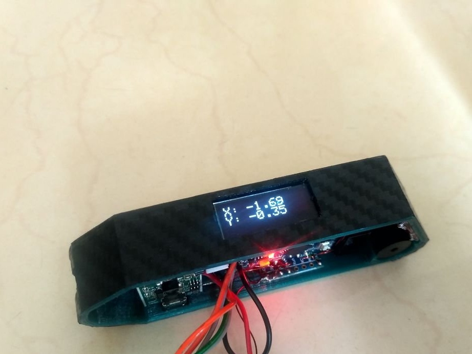
First, the gyroscope is calibrated. Since the MPU6050 accelerometer / gyroscope module is simply glued to the body, it may not be completely flat. Therefore, to correct this error, the following steps are performed.
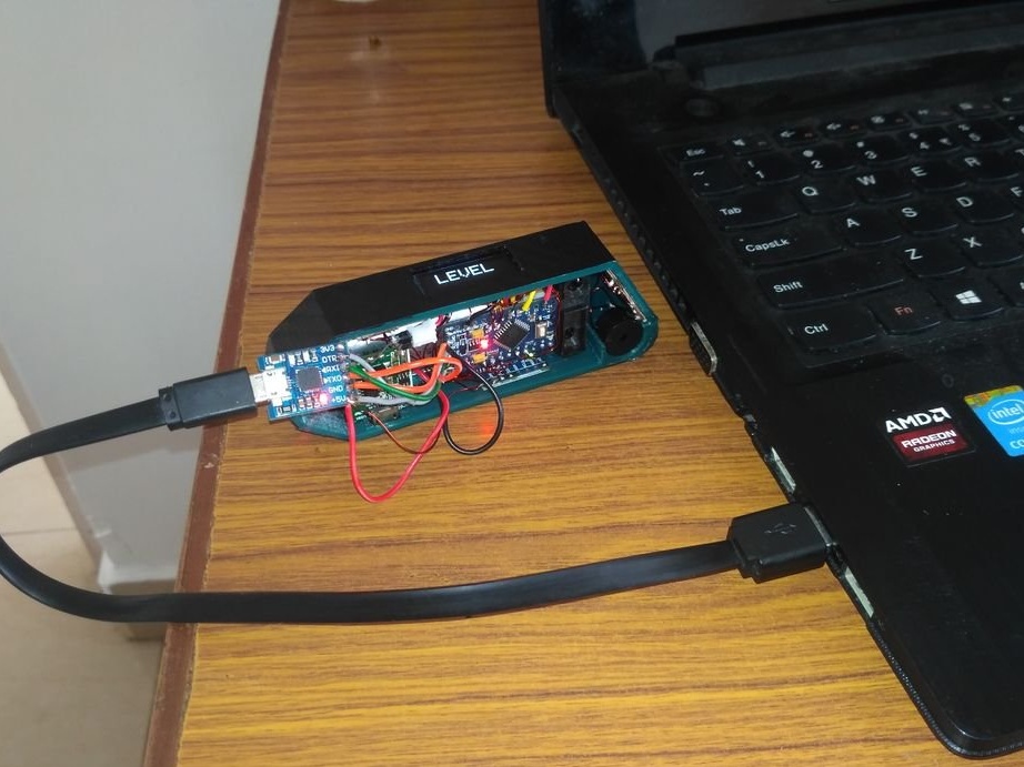
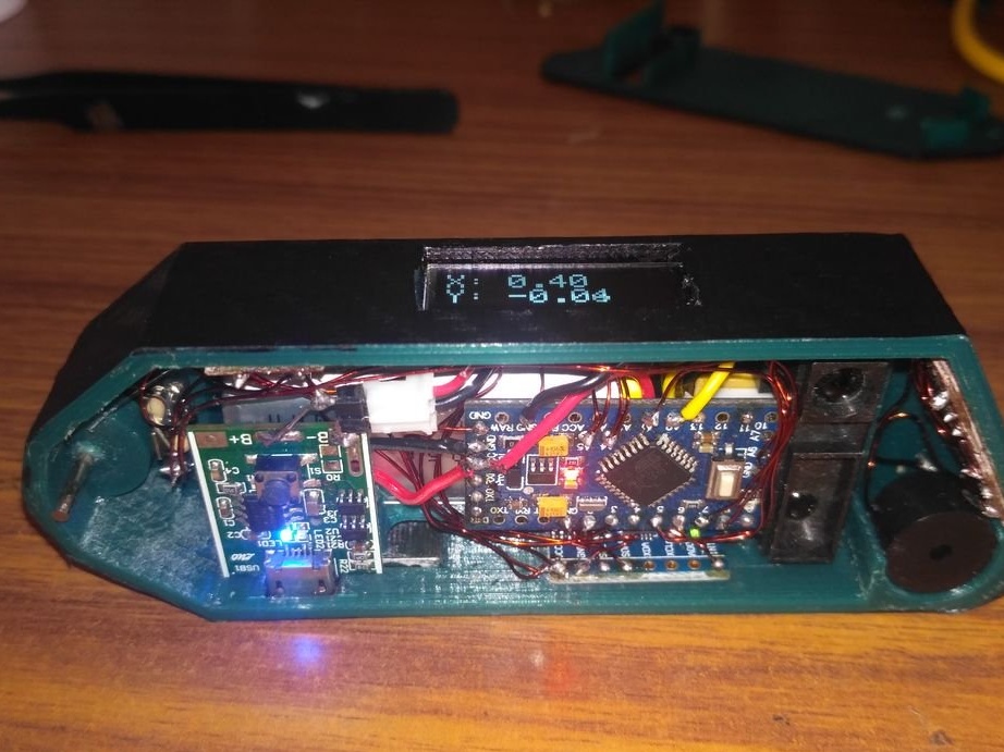
1. Connect the device to the computer and place it on a flat surface.
2. Switch to the LEVEL mode on the device by touching the “M” button and write down the X and Y values.
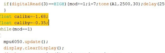
3: Assign these values to the variables “calibx” and “caliby” in the code.
4: Download the program again.
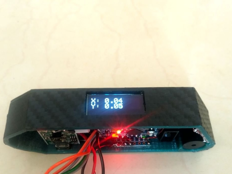
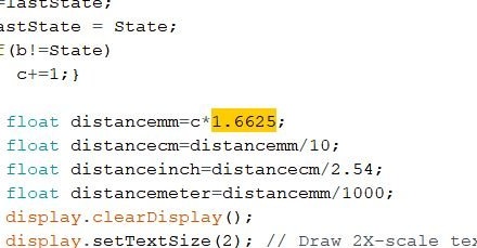
Now calculates distances per wheel revolution.
The number of steps per revolution of the encoder shaft, N = 24 steps
Wheel diameter, D = 12.7 mm
Wheel circumference, C = 2 * pi * (D / 2) = 2 * 3.14 * 6.35 = 39.898 mm
Therefore, the distance traveled per step = C / N = 39.898 / 24 = 1.6625 mm.
Step Fourteen: Testing
Before installing the housing cover, it tests sensors, charge module, buttons, display.
Step Fifteen: Button and Case Assembly
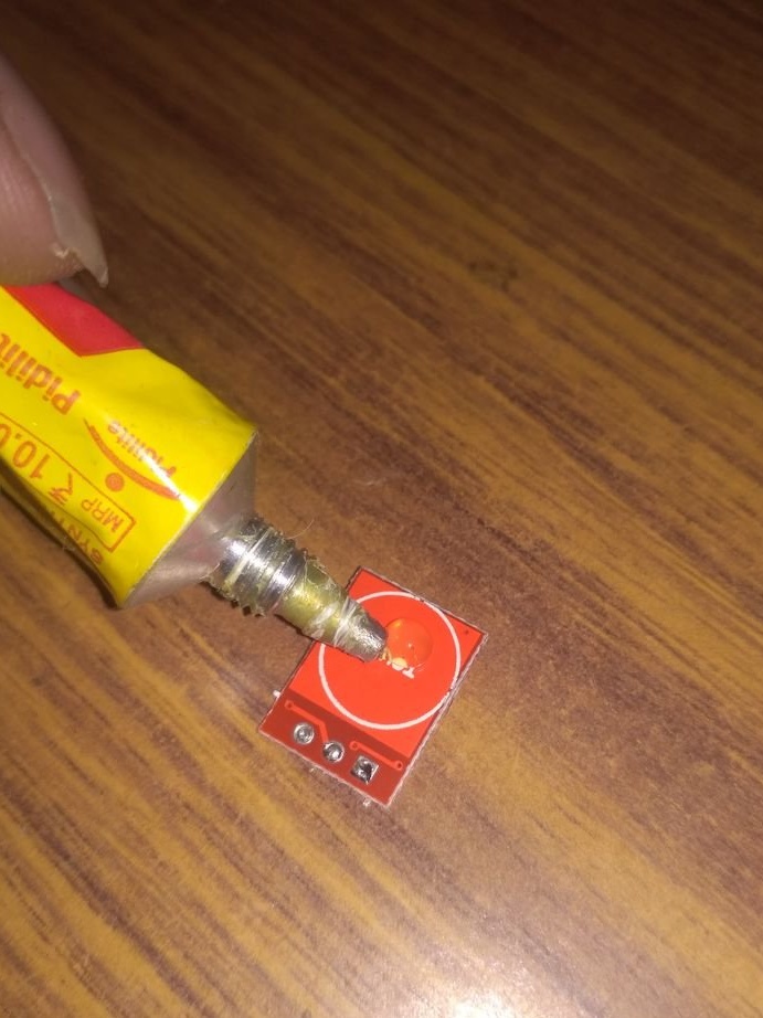
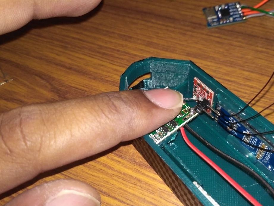
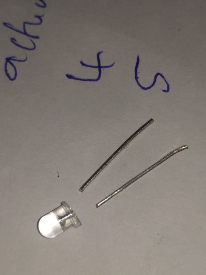
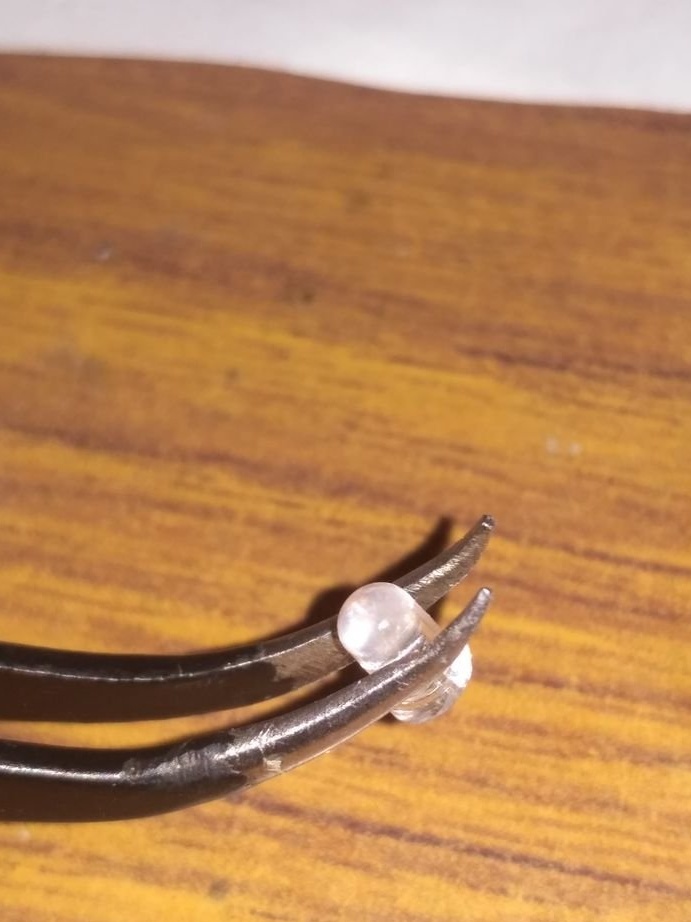
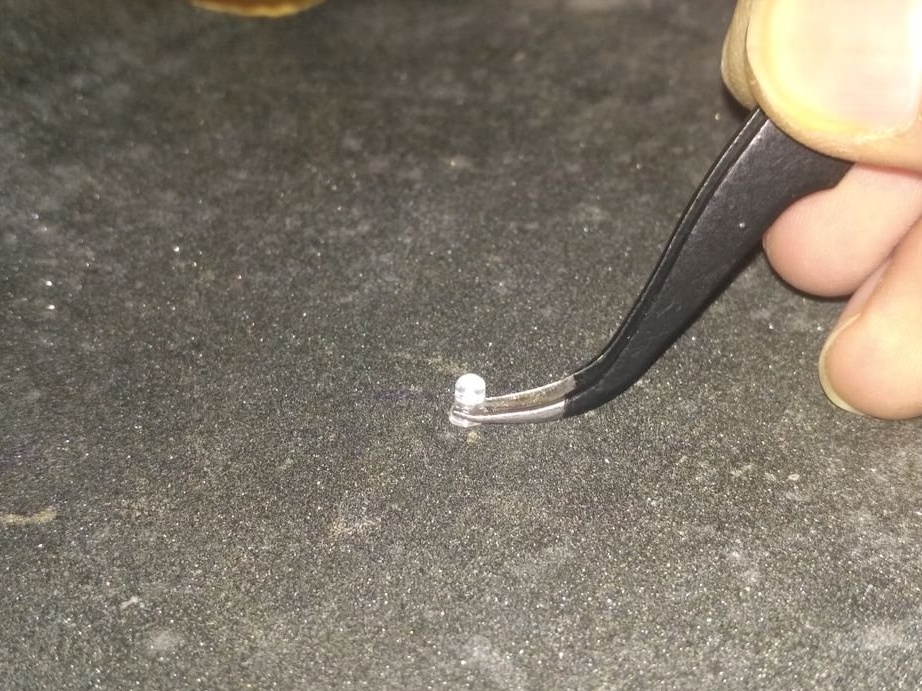
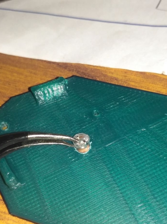
The power button on the charging board is short and the master, cutting the legs, sets an additional LED, which will press the button.
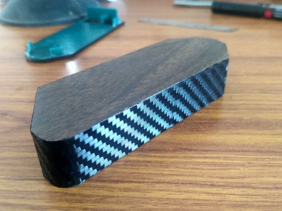
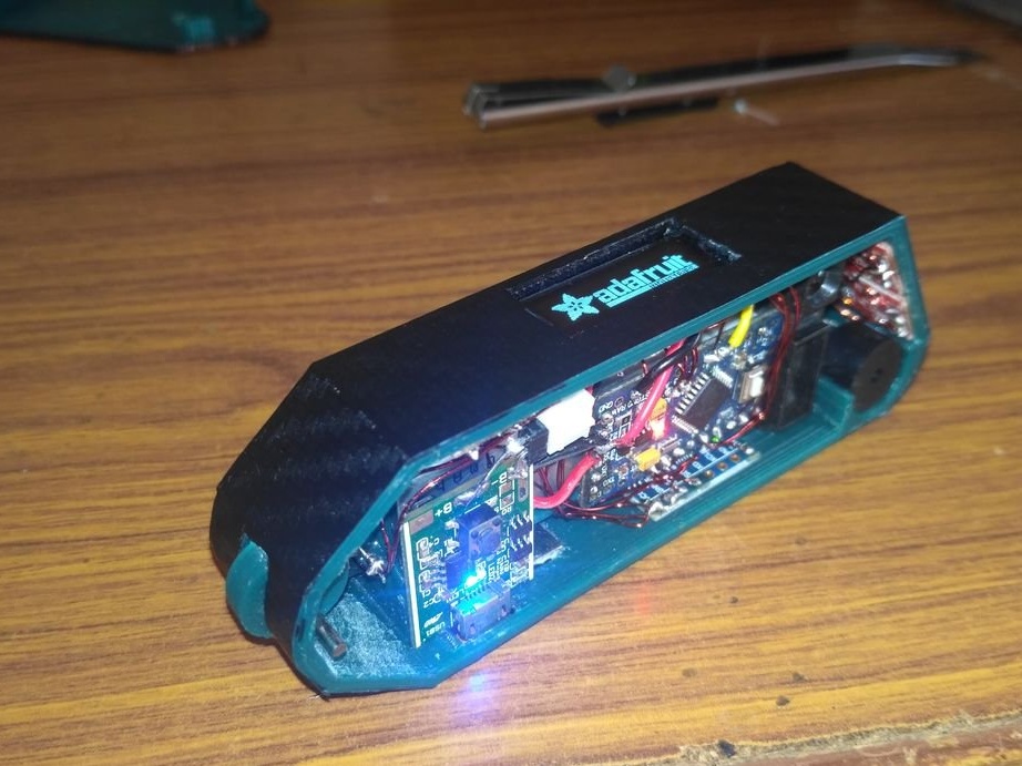
Glues two halves of the body.
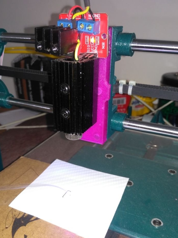
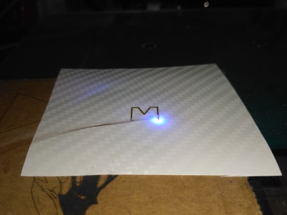
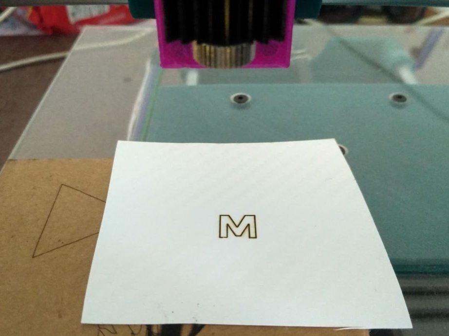
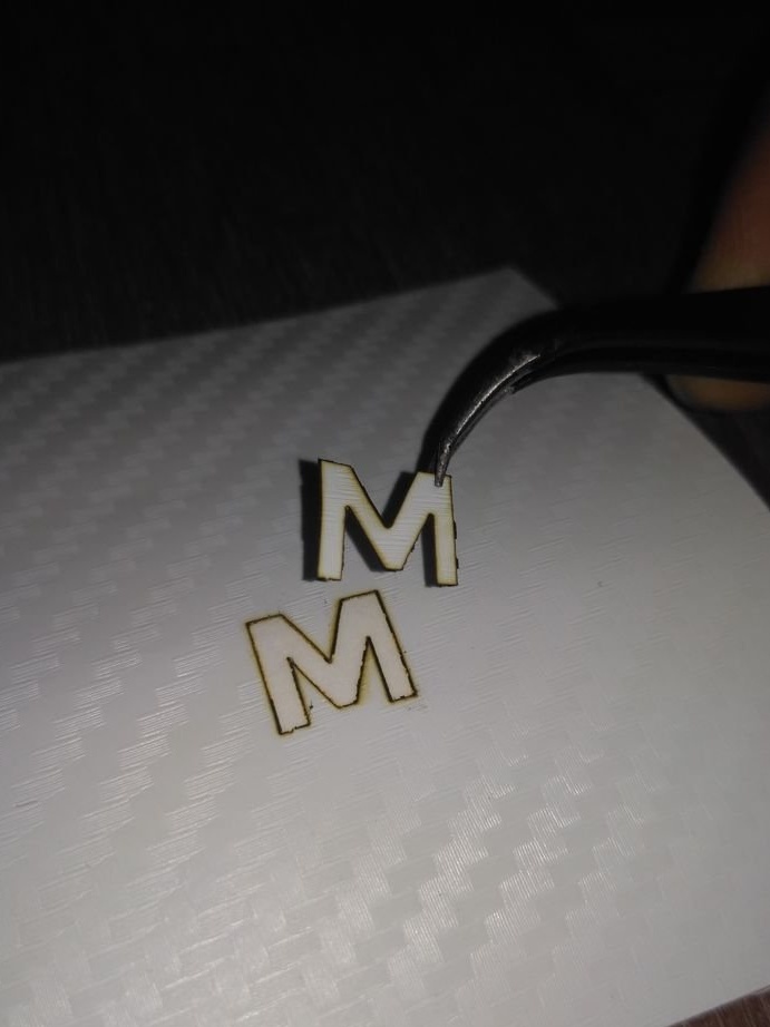
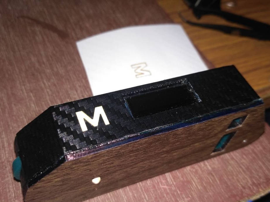
Step sixteen: marking the buttons
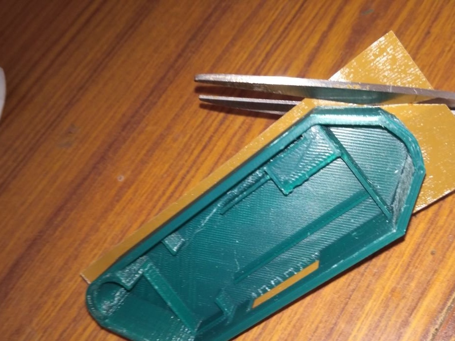
The letters were cut on a laser cutter and then glued to the body.
Everything is ready, it remains only to test the device in operation.