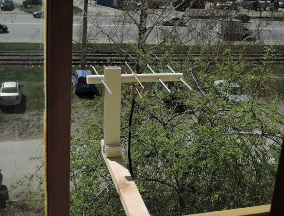
Hello, dear visitors of the site. This article presents a variant of a television antenna for digital television. In our region, Novosibirsk region, digital TV broadcasting was organized on channel 29. And they added 24 channels. Therefore, the antenna must receive these two channels (29kan + 24kan).
To preliminarily check the signal passage, a loop vibrator for ~ 29 channel was made. The antenna was located on the side wall of the panel house on the 4th floor (9 floors). The distance to the antenna of the TV transmitter is ~ 12 km (on the map). Analog signals of still working decimeter range channels were received on the TV. The image was unstable and twofold (and troilo). This is obviously a reflection of the signal from the Earth and the walls of the reinforced concrete house. The antenna was designed-completed to a 4-element wave channel (Uda-Yagi antenna). The 300 ohm antenna output was matched to a coaxial cable (75 ohm) using a balancing transformer. The image is stabilized and not twofold.
Since the bandwidth of the received signal at the 4-element wave channel is small, therefore, the average frequency Fav was chosen. (between 24 channels and 29 channels) to calculate the antenna. From the reference 24th channel corresponds to frequency F ~ 498MHz and for 29th channel - F ~ 538MHz. We get Fav. = (498 + 538) / 2 = 518 MHz
When calculating the antenna operate on a wavelength of λ. And for 518MHz λ ~ 57cm
Materials and tools for manufacturing the antenna:
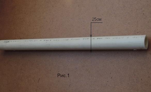
- polypropylene pipe d = 25.4mm, wall thickness ~ 4mm, length ~ 32cm (traverse) Fig. 1
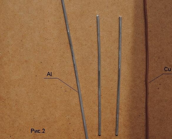
- Aluminum rods. Alloy from the Polish antenna d = 4,5mm (directors and reflector) Fig. 2
- copper wire d = 3.6mm, length ~ 61cm (vibrator)
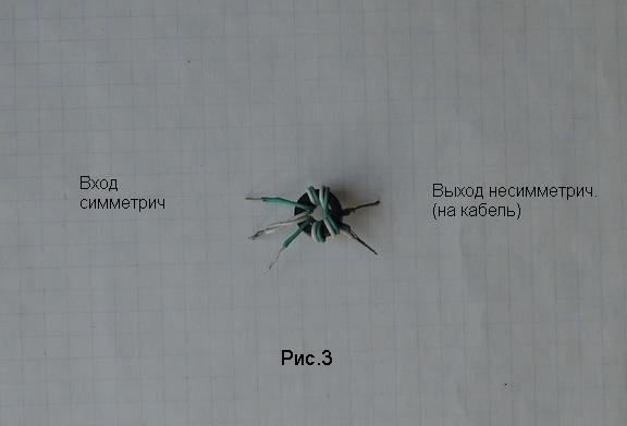
- high-frequency transformer (from a plate amplifier 300/75) Fig. 3
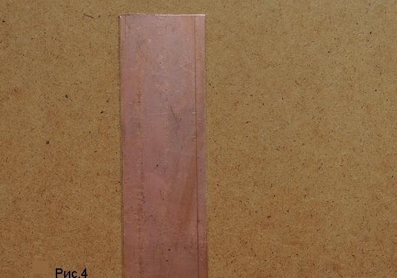
- fiberglass (2mm) single-sided, 41x80mm Fig. 4
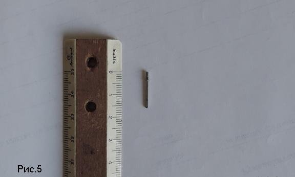
- pin-pin from the connector (brass) 1.2x1.2x18mm Fig. 5
- 2 bolts with washer and nut M2.5
- 2 bolts with washer and nut M3
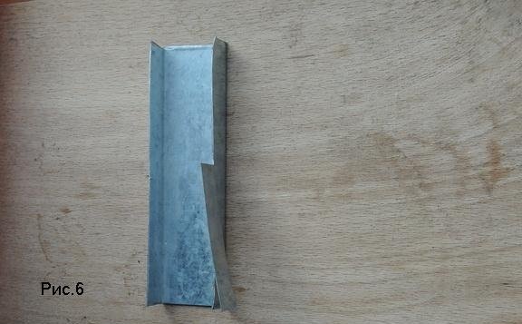
- steel strip galvanized 0.5mm, 42x10mm Fig. 6
- hacksaw for metal, hacksaw blade cutter
- drill with drills
- file for metal
- soldering iron with solder POS61, flux, tweezers
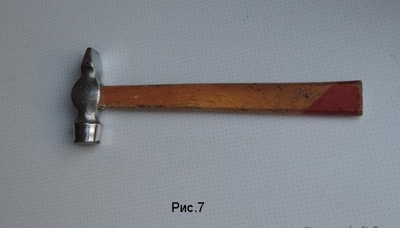
- hammer Fig. 7
- ruler, scriber
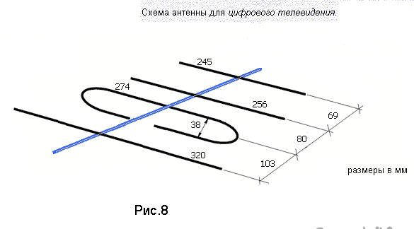
The calculated dimensions of the antenna parts are shown schematically in Fig. 8
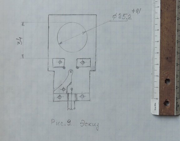
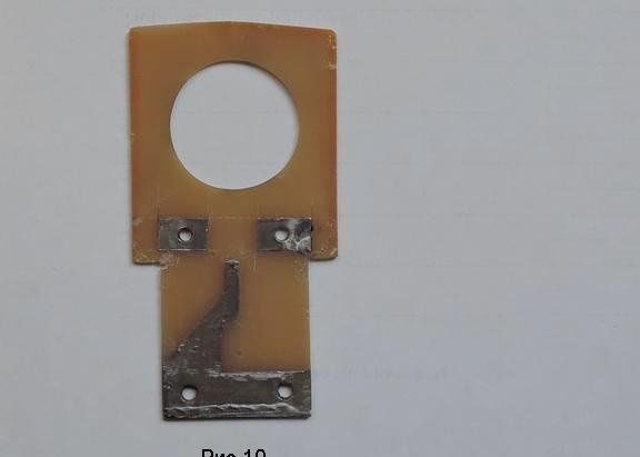
A sketch of the matching scarf is shown in Figure 9. The topology is not complicated, therefore, etching was dispensed with. Copper foil is simply cut with a cutter. The fabricated and tinned shawl is shown in Fig. 10. A pin is hammered into the 1.1mm hole and cut off with a protrusion from the scarf ~ 3mm.The symmetric input of the transformer is soldered to the contact pads of the vibrator, and the unbalanced output is soldered to the cable.
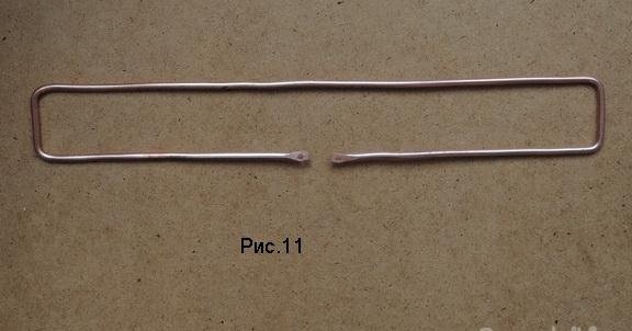
The vibrator is made in size from Fig. 8. The ends of the frame are flattened with a hammer. And at a distance of 1.8 cm holes are punched (punch) and countersink up to 2.5 mm, as in the photo Fig. 11
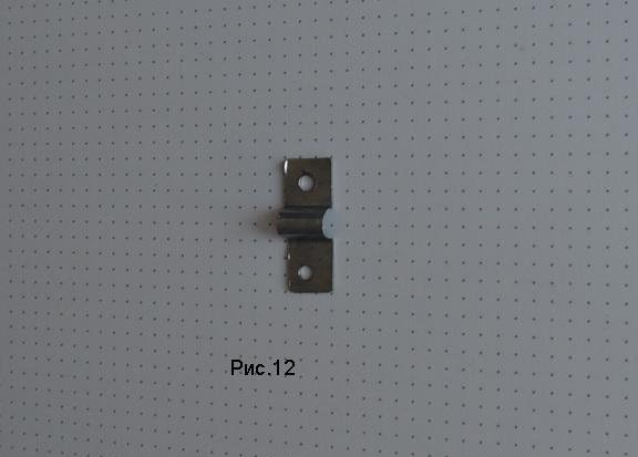
The mounting plate for the cable is made of a galvanized strip (Fig. 12). I had a cable like PK75-4-11 with internal insulation d = 4.8mm. For another cable (with a different diameter of internal insulation) you need a different bar.
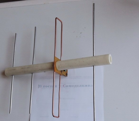
In a plastic tube (traverse) holes for directors and a reflector are marked and drilled. First, the matching handkerchief is tightly mounted on the tube, then the directors and the reflector are clogged with a hammer.
I do not have a digital tuner on the TV, so a receiver (HDT2-1202) was purchased for this antenna.
The antenna was mounted on insulating materials, on pieces of plastic.
Disable analog television broadcasting in Novosibirsk promised in April. Completely complete the shutdown and switch to digital TV is now planned in June 2019. How many rusty metal on the roofs! The so-called "collectives."


