

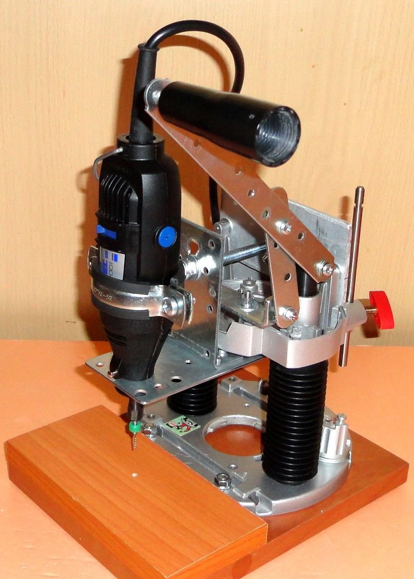
This design was made for precise drilling of printed circuit boards with special drills (drills) based on tungsten carbide.
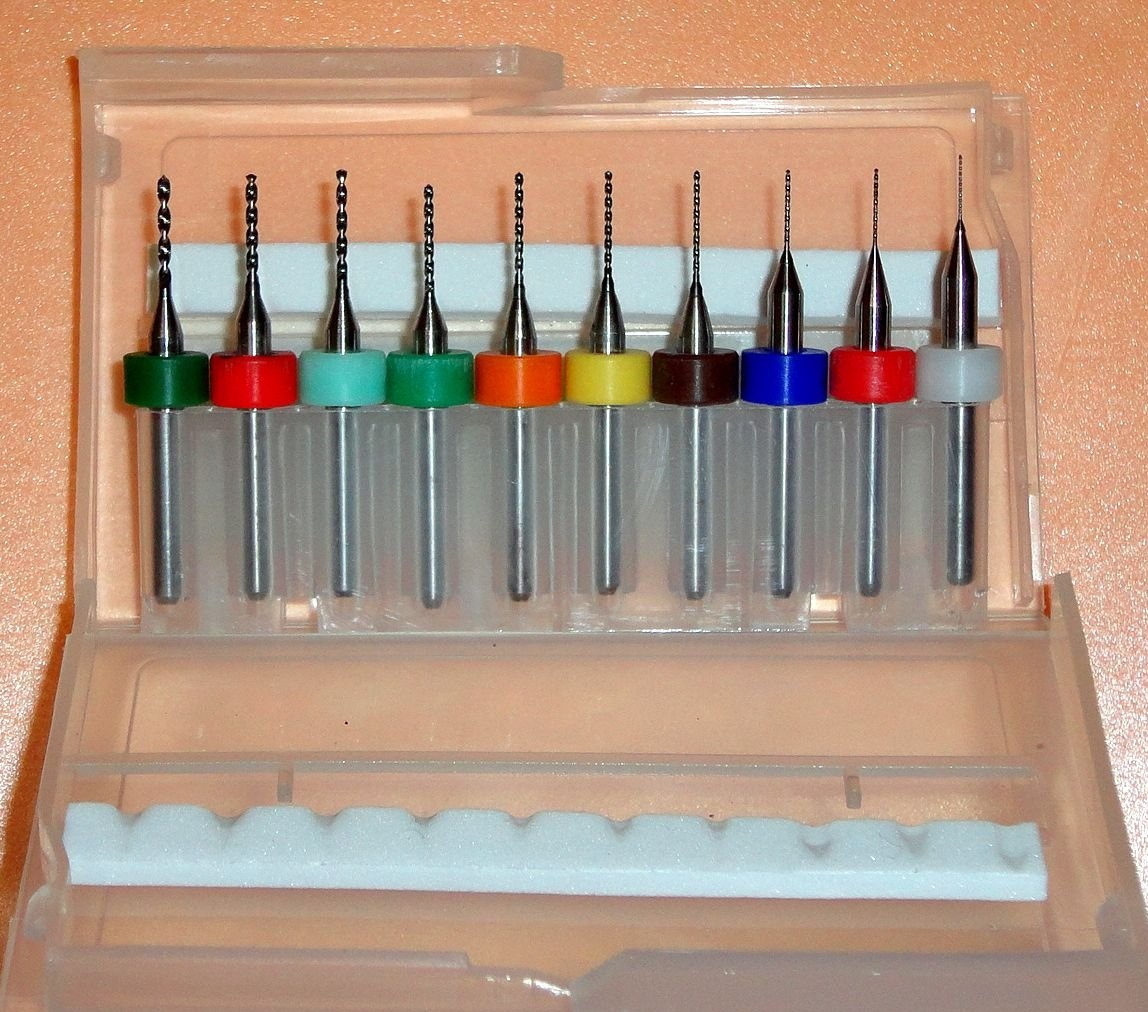
These drills are perfectly drilled and almost do not blunt from fiberglass. But they are quite fragile and easily break when accidentally tilting the power tool. After breaking a couple of thin drills, I decided to start manufacturing a drill stand.
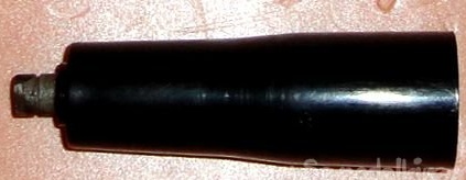
I had a burnt hand milling cutter lying in the trash (there was no point in repairing it - the price of the issue).
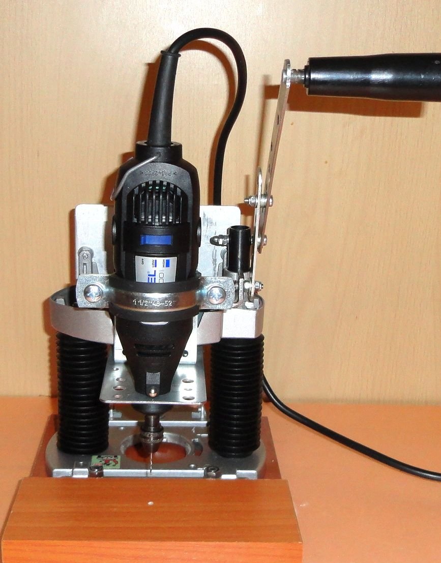
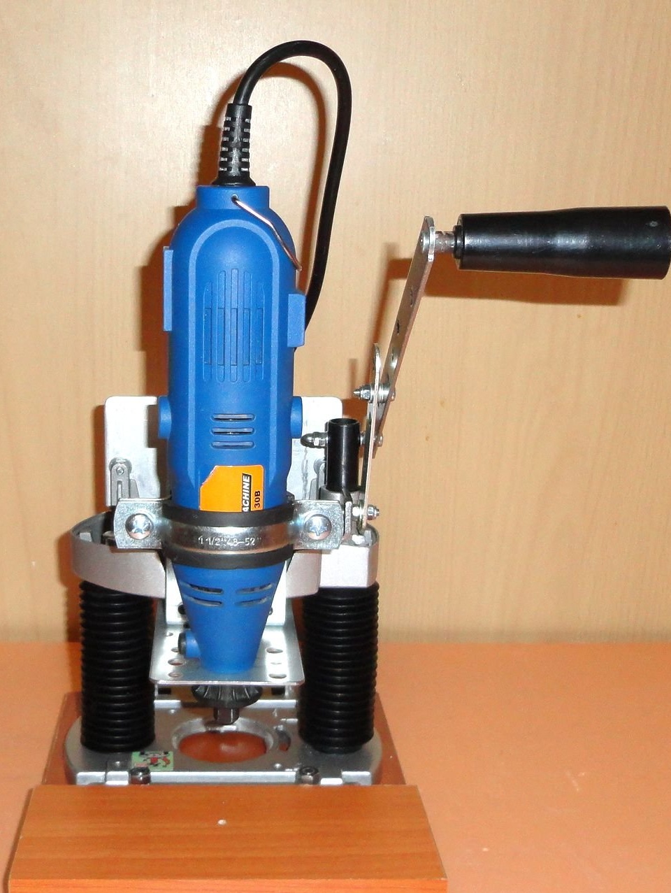
The idea was to use its parts and standard products from a hardware store with minimal refinement and minimal cost and time. And universality, i.e. the ability to install as a proprietary MFI firm Dremel,
and Chinese IFI options.
In this design was used:
- details from the manual milling cutter BOSCH POF-1200
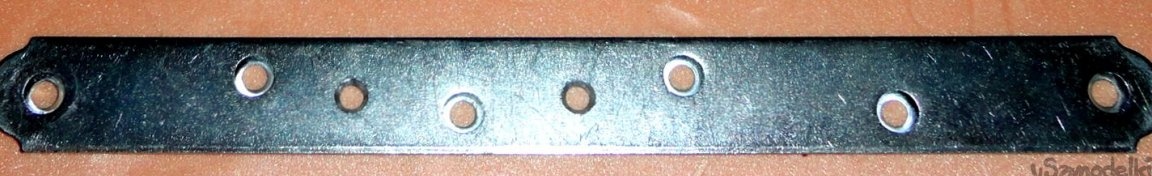
- standard mounting plate 180x65x2mm
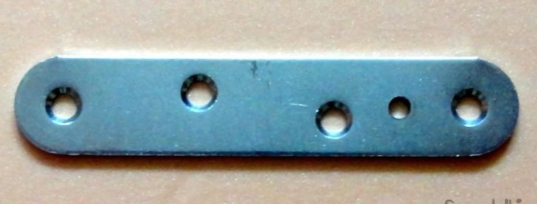
- standard mounting plate 200x20x2mm
- standard mounting plate 100 x20x2mm
- standard corner 50x90x55x2mm
- standard corner 100x100x20x4mm
- metal clamp with nut 1 1/2 48-52mm
- hairpin M8-120mm
- aluminum plate (silumin) 120x60x4mm
- LDSP 225x180x16mm
- chipboard 180x80x16mm
- fasteners: M4, M5, M6, M8.
Of the tools used:
- Dremel MFIs
- drill stand
- cutting machine
- jigsaw
- screwdriver
- files
- clamps
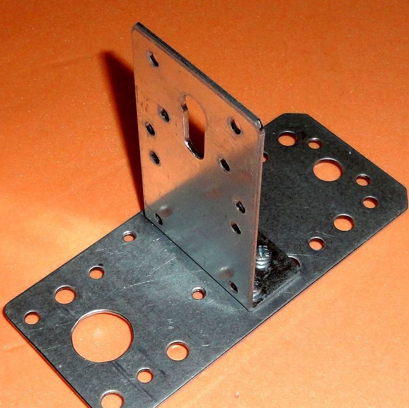
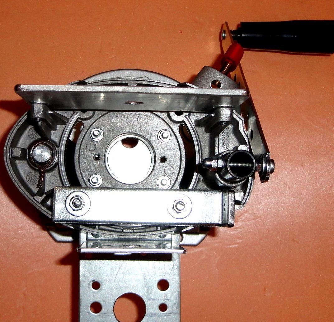
All marking and further processing of structural parts was carried out immediately in place. The supporting strip is made of a metal standard mounting plate 180x65x2mm. The plate is selected taking into account the coincidence of the holes with the mounting holes of the mill body.
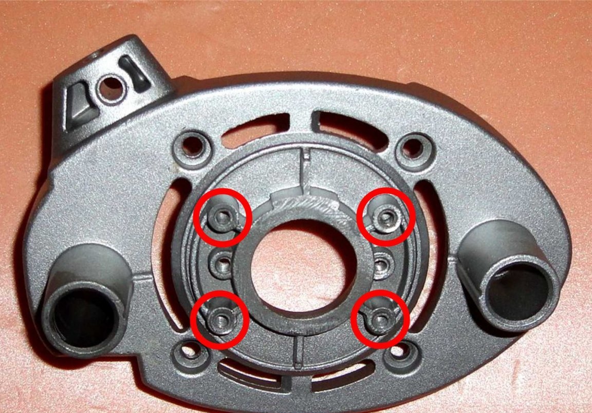
Two holes were drilled under the factory corner holes in the bar and two holes were machined. An opening was made for the MFI casing with a diameter of 19.5-20 mm. The excess is cut off. The result is a size of 145x65mm.
In the corner, the factory hole is machined for a 8mm stud. The excess is cut off. The outer dimension is 25x90x55mm.
Support plate with installed corner. Mounting is done with M4 screws.
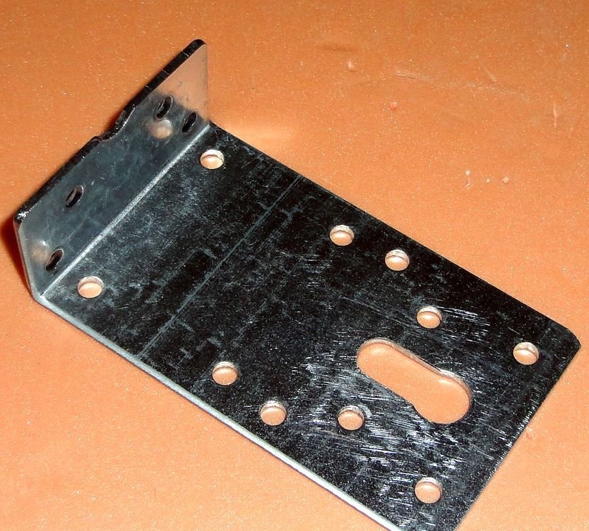
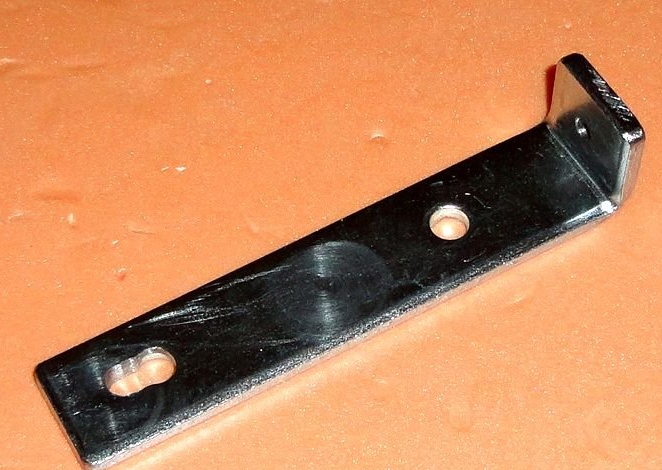
The emphasis of the lever mechanism is made of a standard metal corner 100x100x20x4mm.A 2mm thick corner will not work. it starts to spring and deform (checked). In the resulting part, factory-made holes are used, one of which had to be punched. And one hole was drilled under the axis of the link rod with a diameter of 4 mm. The resulting outer dimension of the part is 100x20x20mm.
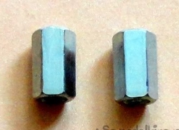
The emphasis is attached to the body with the help of M5 screws through the racks which are used 18 mm M6 connecting nuts.
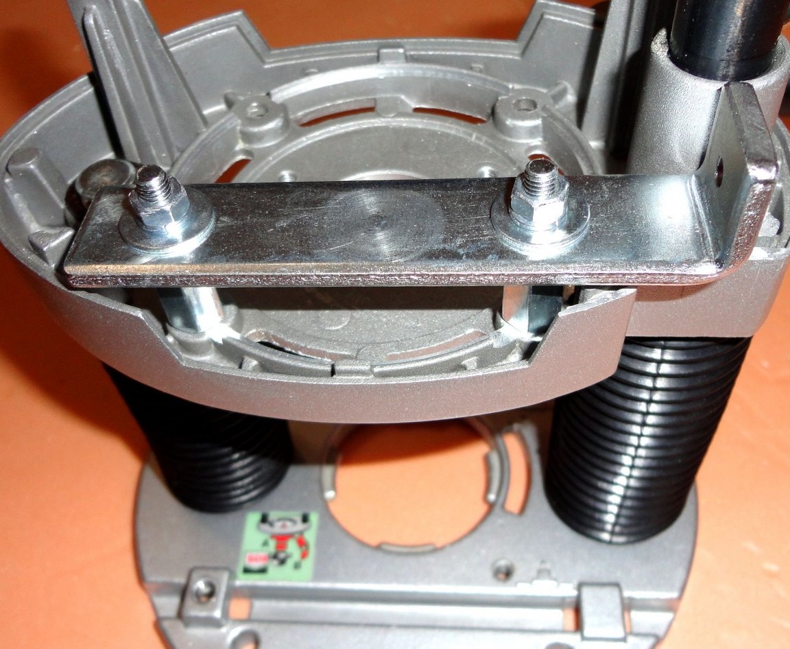
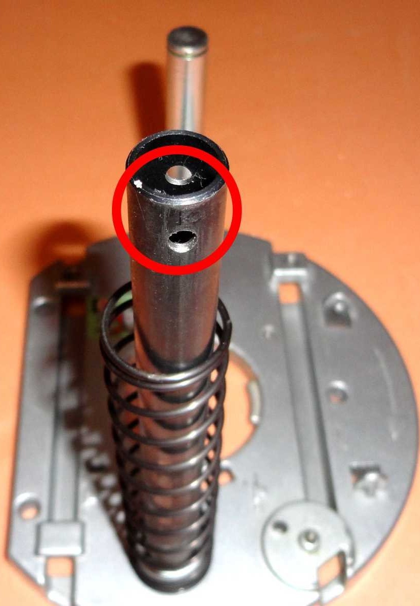
A through hole was drilled in the tubular guide for the lever axis with a diameter of 4 mm.
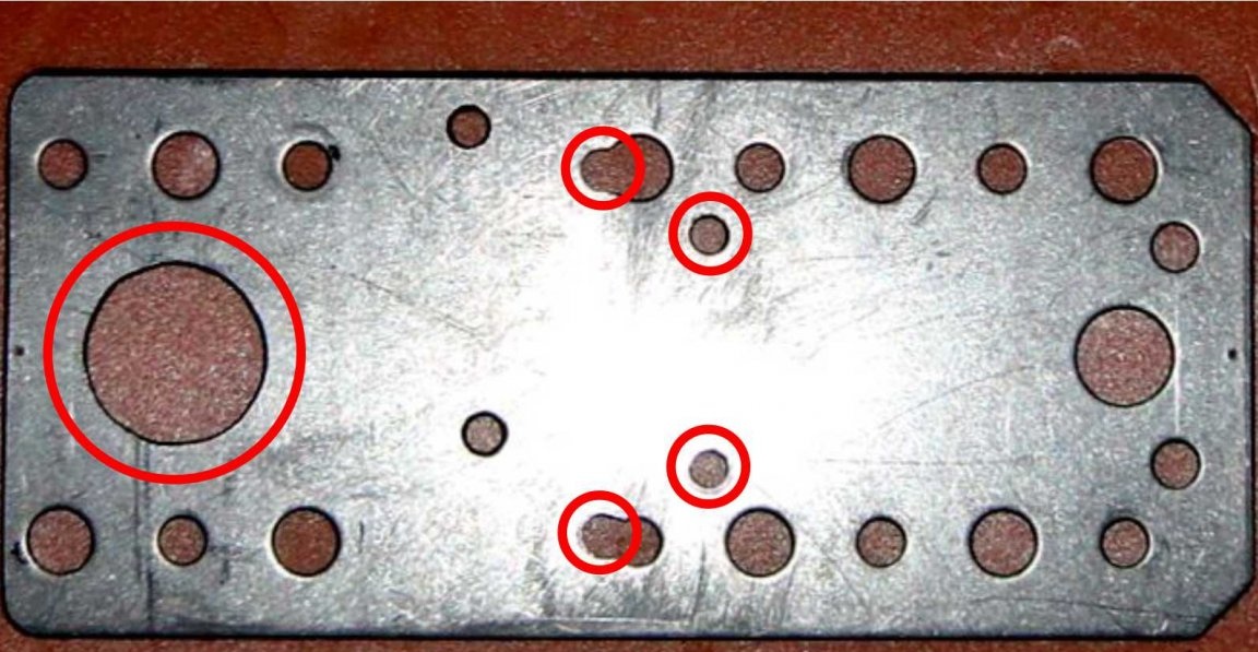
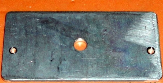
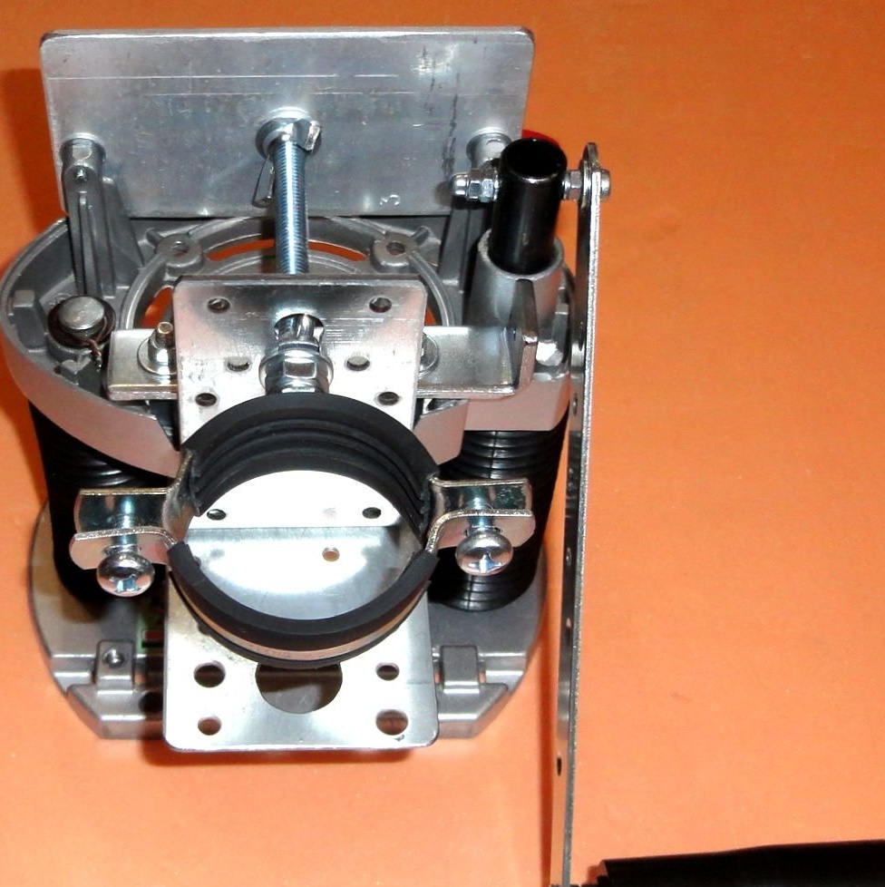
The back plate of the aluminum holder (silumin) is cut with dimensions of 120x60x4mm. In it, holes were drilled (with a margin, for alignment) lateral 4.5 mm, central 9 mm.
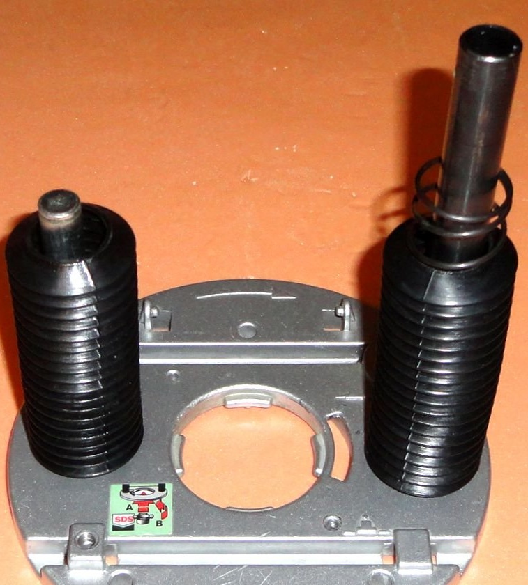
The design uses only one spring, which is quite enough. The spring is mounted on a tubular guide. Both guides are covered with thermowells.
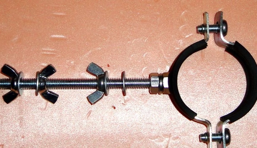
The holder fasteners use M8 nuts of the “lamb” type, for the convenience of adjusting the inclination of the drill. The M8 hairpin is attached to the clamp through a groove washer and secured with an additional nut.
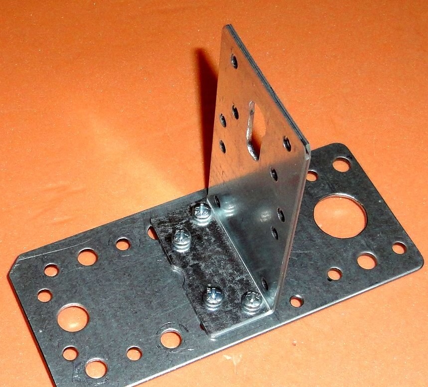
The base plate with the corner of the holder is attached to the housing with four M4 screws.
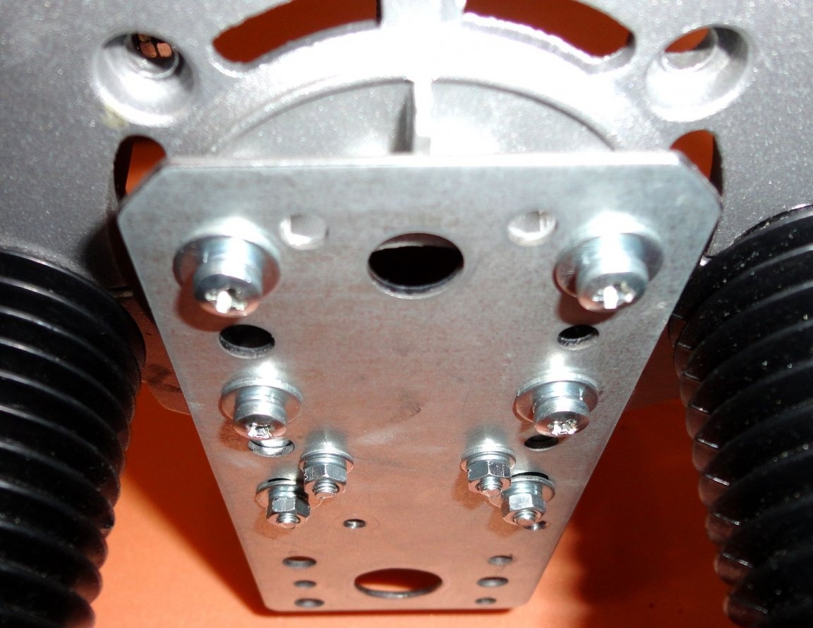
The back plate of the holder is attached to the body with two M4 screws.
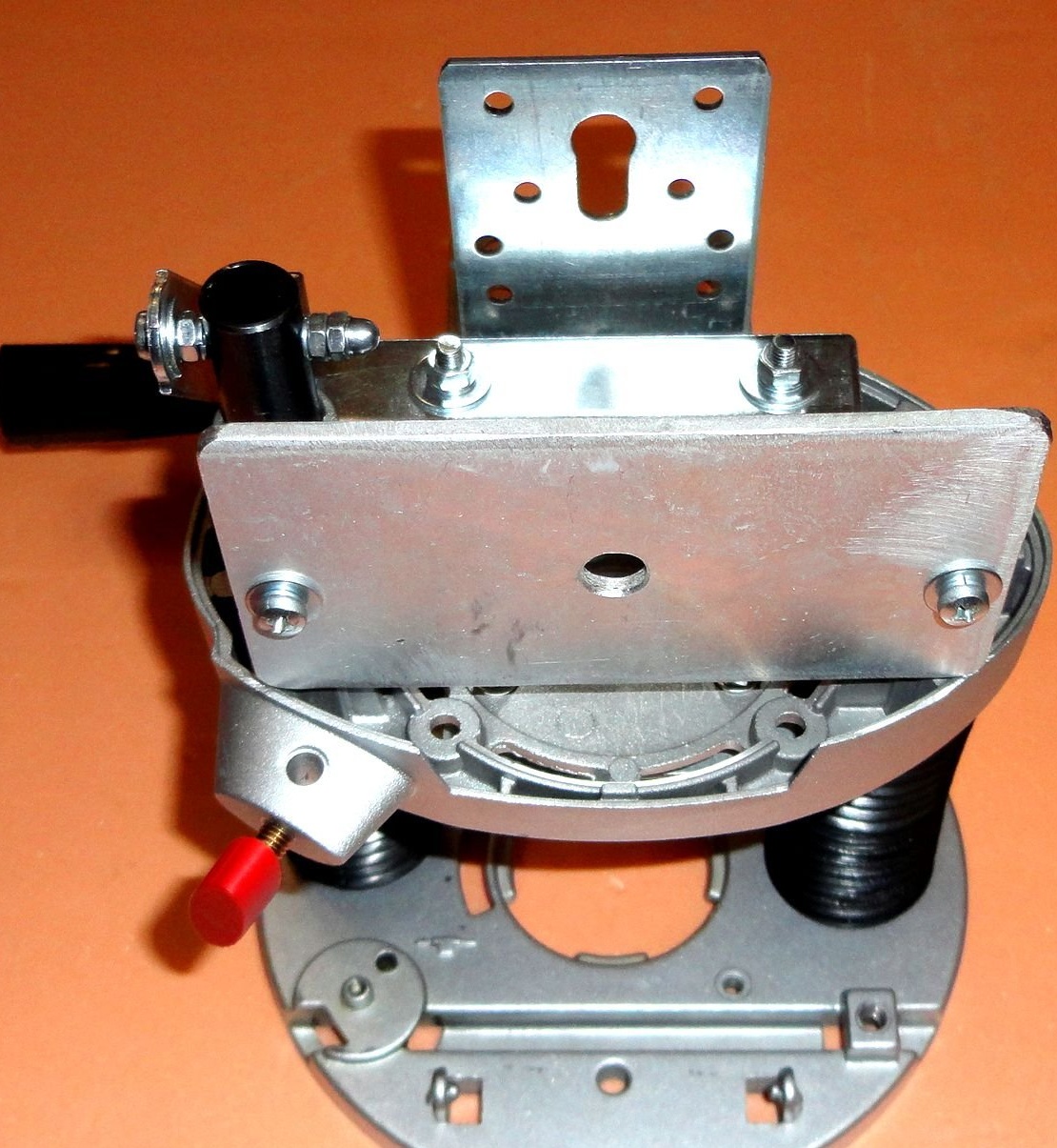
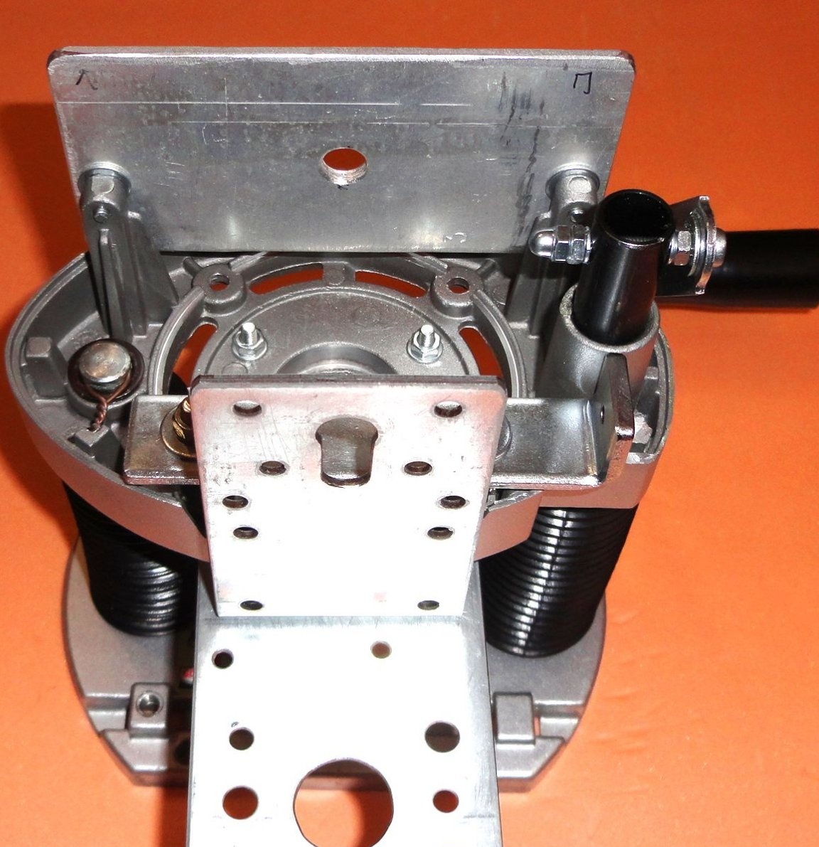
Mounted holder.
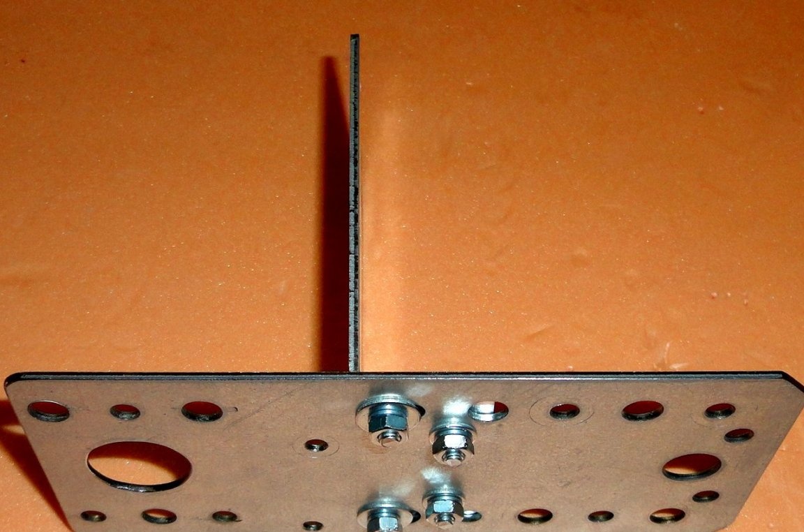
The bed and the supporting table are cut from chipboard and have dimensions 225x180x16mm and 80x180x16mm. Self-adhesive rubber thrust bearings are glued on the back side for of furniture. The support table easily changes to different options.
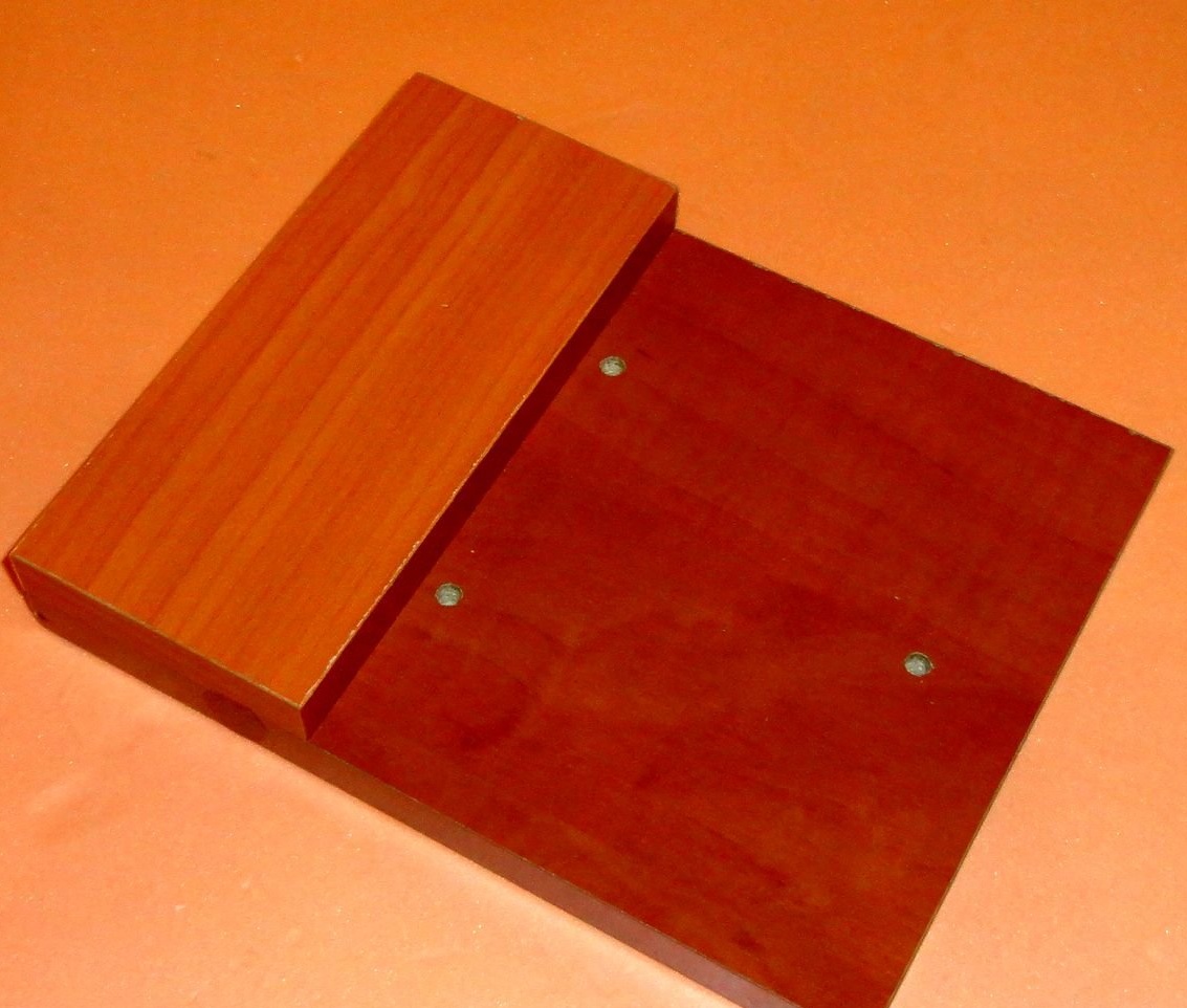
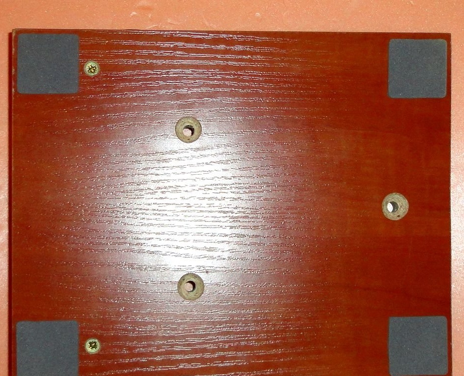
The mill base plate is attached to the bed with three M6 screws.
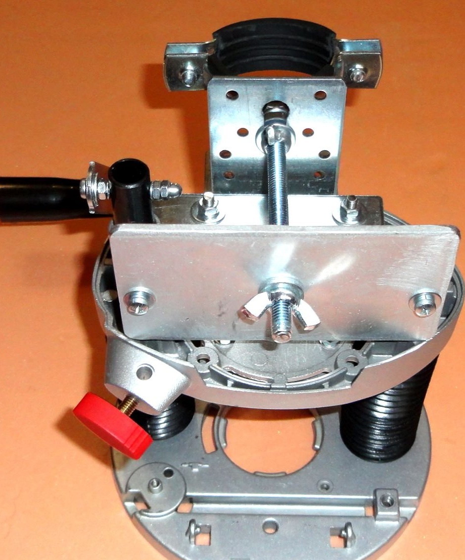
The lever mechanism is made of ready-made mounting plates 200x20x2mm and 100x20x2mm, in which additional 4mm holes are made.
The axles used are M4 screws. The axles on the tubular guide and the lower stop are rigidly fixed with nuts and groove washers. The traction axis rotates freely. Washers are also used to level the entire mechanism. Self-locking nuts (with rubber inserts) are also used in the mechanism.
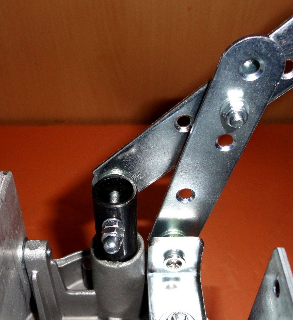
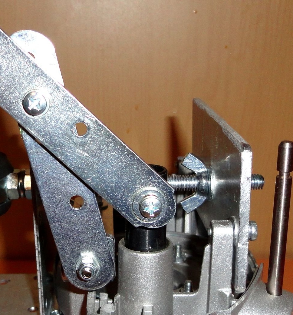
A part from the mechanism of the same milling cutter was used as a lever handle. Which is fixed to the lever with an M4 screw.
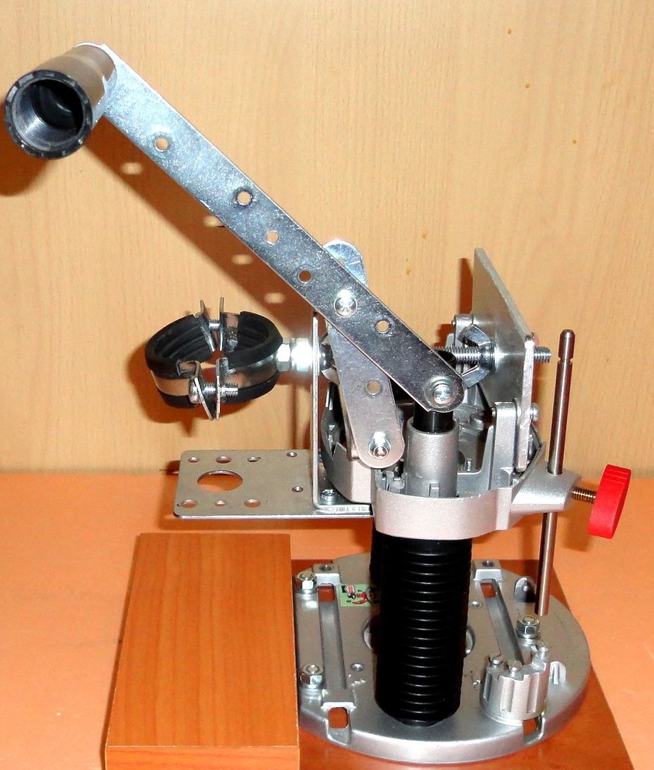
For convenience, an adjustable depth stop is left from the milling cutter. The moving parts of the linkage and the guide rails are lubricated. Screw fasteners are made using engraving washers.
After installing the MFI in the rack, the angle of the drill relative to the support table is leveled using the rear adjusting nuts.
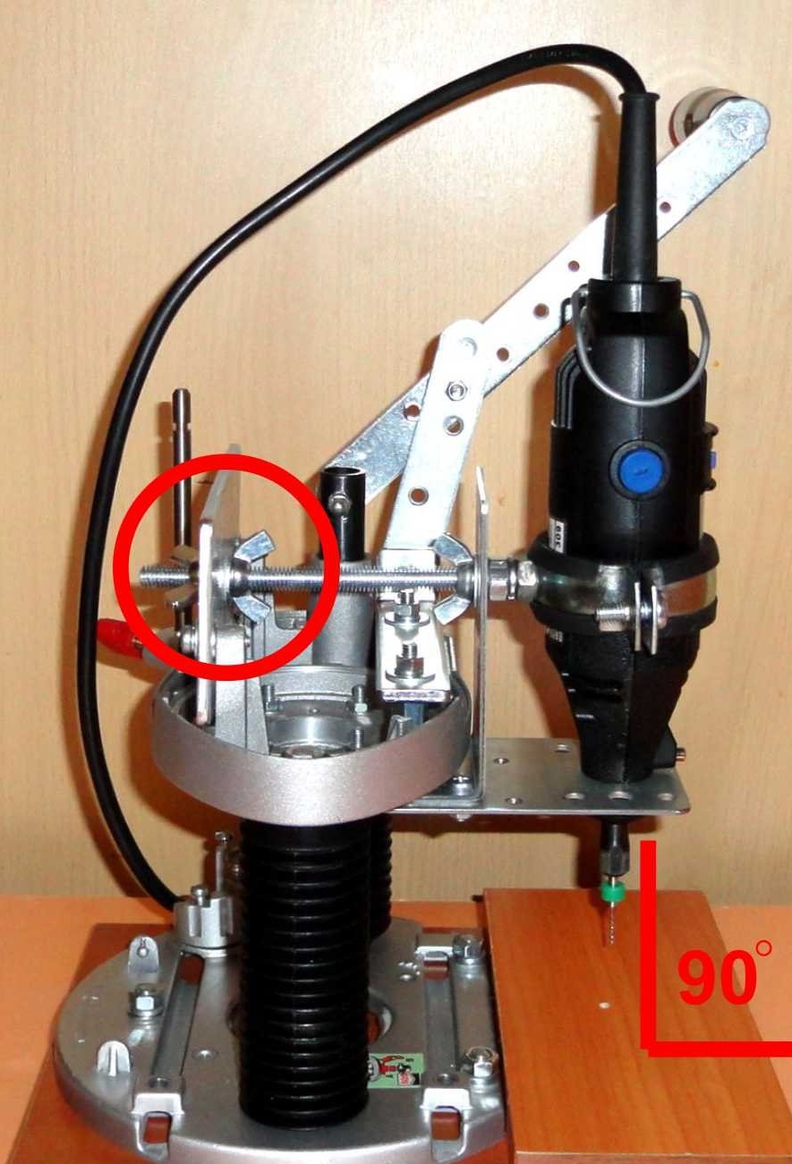
The design is very stable. The shoulders of the lever were selected successfully, the body travel along the guides is light and smooth. No backlash is noticed. Drilled with a drill 0.3 mm, the drill does not lead. It is possible to drill without prior pitting, which is convenient with LUT technology for the manufacture of printed circuit boards. The lever provides the maximum possible stroke along the guides.
Unfortunately, the lock washer mounted on the rail was lost, temporarily replaced by twisting of steel wire.
Because in the design of the lever mechanism used standard products, then in case of wear there is no problem replacing without unnecessary troubles. I didn’t do the backlighting, since when working at the desk, a desk light was enough.
While working on this product, I also recalled a Soviet metal children's designer, where there were a bunch of parts with holes, cogs and nuts !!!
If you need additional information, write to the post office, I will try to be sure to answer.
Feedback, suggestions and comments are very welcome.