

Immobilizer - English immobiliser - "immobilizer". Anti-theft device that blocks important circuits in the ignition system. Regular immobilizers do not allow to start the engine, immobilizer manufacturers for further installation went further and not only block the engine, but create the appearance of a malfunction in the ignition.
I set the usual secrets, toggle switches, reed switches with reels, etc. I read in a magazine that any non-standard lock increases the time it takes for an attacker to steal a car by about 20%.
I am not an expert in hijacking, but I had experience unlocking simple alarms with a non-standard approach, maybe this is true. The disadvantage of passive interlocks is that by ringing the circuit you can determine where the power is not enough and where the signal does not pass. Here the active lock is already precisely in these 20%. A "floating" fault is more difficult to find, verified.
Immobilizer on the K561LA7 and K561LP2 chip.
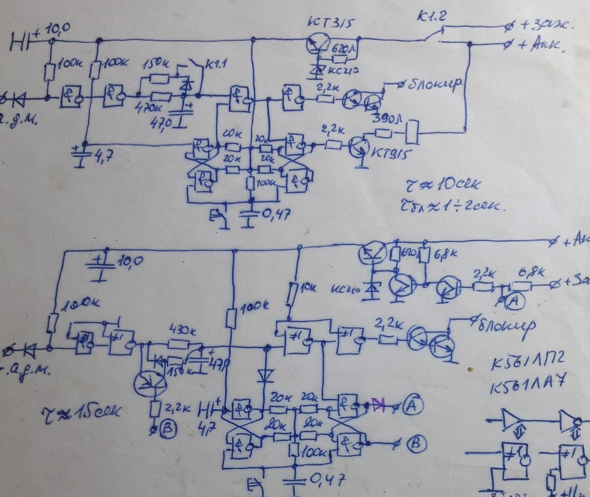
Here are two options for the immobilizer, with and without relays. Once I made and set such, I brought the circuits not for discussion and repetition, but for comparison with the circuit on the microcontroller.
Algorithm: after starting the engine, 15 seconds are given to press the button, if not pressed, the lock is turned on and holds until the engine stalls. After the engine stops, the lock is turned off, a 2-second timer to turn off the lock is turned on. If you start the engine again without pressing the button, the engine is blocked after 2 seconds and is removed only after the engine stops.
When the ignition is turned on (the engine is not running), all power is normal, when starting, the signals are registered until there is no blockage. Thus it is impossible to go, but finding the “malfunction” is more difficult.
There are drawbacks in circuits with discrete elements - a lot of details (reliability decreases), time delays are implemented by RC circuits (temperature dependence), unchangeable work logic.
Immobilizer on the PIC12F629 microcontroller with a button.
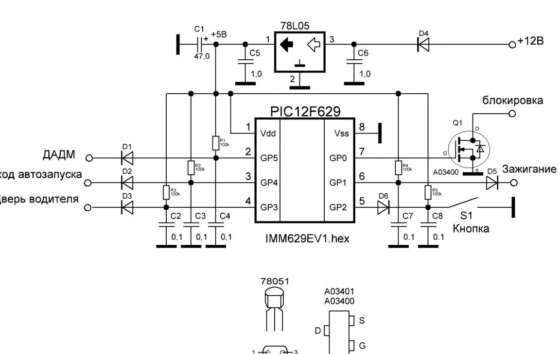
DADM - emergency oil pressure sensor
Programmatically repeats the algorithm of operation of the circuit on discrete elements, but more complex, plus the ability to autostart, control of the driver's door to implement the "Anti-hijack" function, "floating" lock (when connected correctly, it creates the appearance of a faulty ignition system) and non-volatile state memory. After removing the battery, the program rises to the previous position.
I did not specifically set the status indicators, just press the button (we show that in car master). The service mode is implemented by the connector. Temperature condition from -40 ° С to + 85 ° С. Currentconsumption 1mA (microcontroller datasheet). The blocking place is selected for a specific car.
Hex file:

In detail, I can write the algorithm of work in PM, if there is a desire to repeat.
The installation location of the button is arbitrary, instead of the button you can put the reed switch under the door trim or on the dashboard. Hide the magnet in a keychain or signet.
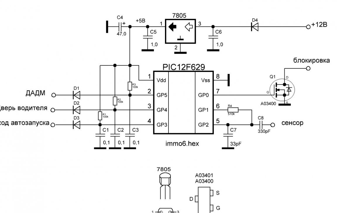
Immobilizer on PIC12F629 with sensor.
DADM - emergency oil pressure sensor
Hex file:
The algorithm as in the first scheme, the service mode is implemented in software. The sensor can serve as a self-tapping screw screwed into the dash, but not shorting to ground. Or some metal icon, icon ... The wire from the device to the sensor is preferably not more than 40 cm.
It was not possible to programmatically implement a reliable contactless sensor, Aliexpress came to the rescue. Sensor on the TTP223 chip. Using this chip, you can make a non-contact sensor, glued, for example, on the back of the panel. Response distance up to 1cm.
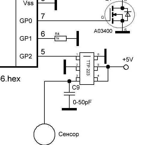
The sensitivity of the sensor is regulated using a C9 capacitor with a capacity of up to 50pF (the smaller the capacity, the higher the sensitivity, I set it from 22 to 33pF) and the size of the contact pad, if the microcircuit is soldered separately.
The chip itself is very small, it is difficult to solder, so it is better to use a ready-made board with a touch pad.
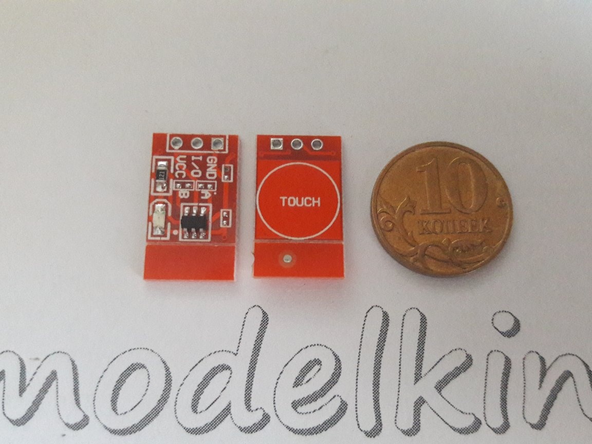

It is necessary to add jumpers - 6 contact to ground, 4 contact to + 5V (jumper A on the board), this is non-latching mode, active low level at the output (touched the sensor, 0 at the output, released - 1). The output can be connected to input 5 of the PIC12F629 microcontroller in the first and second immobilizer circuit without changing the firmware.
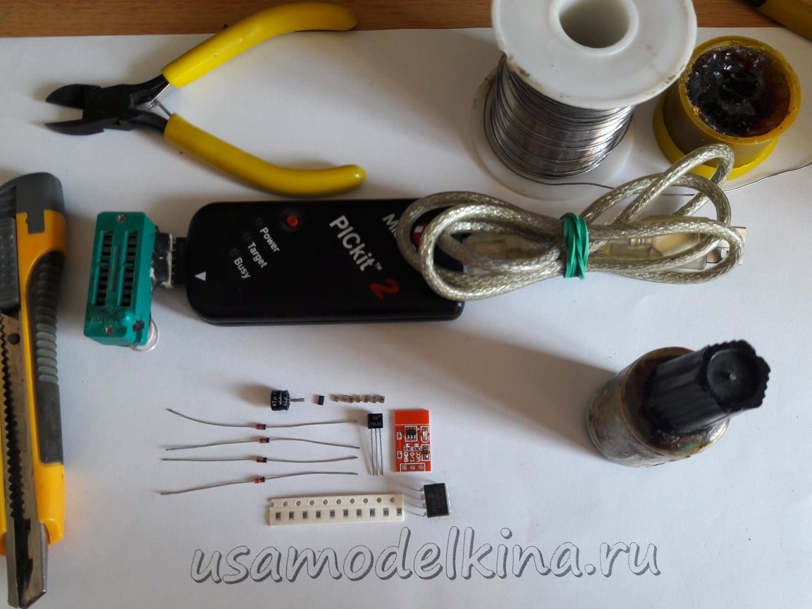
Details:
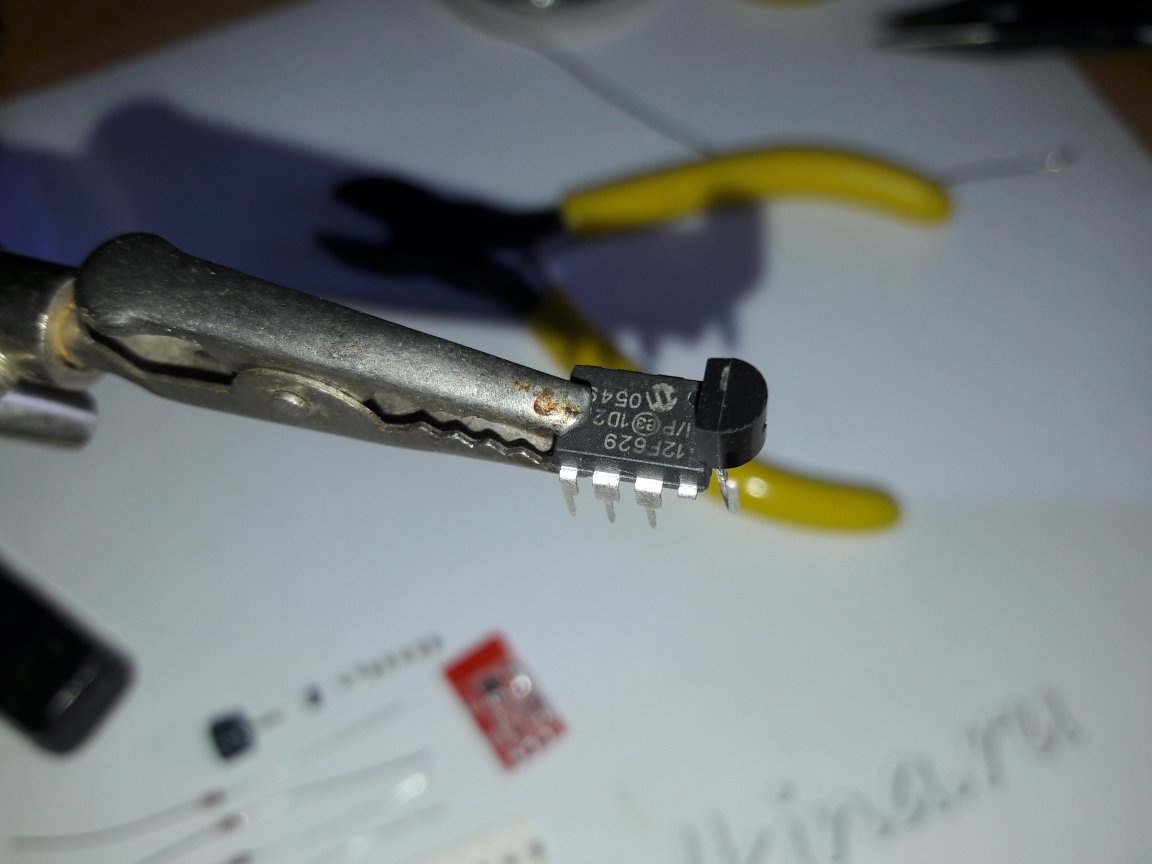
1. PIC12F629 -1; (Chip-Dip price - 97 rubles, on Aliexpress I bought at 37 rubles.);
2. 78L05 -1; (5V voltage stabilizer);
3. All resistors 0.125W, ratings on the circuit;
4. Diodes at the inputs D1, D2, D3, D5 (any low-power);
5. Diode for power supply D4 - 1N1404; (more powerful, 1A);
6. Ceramic and electrolytic capacitors are indicated in the diagram;
7. Transistor Q1– AO3400 (A09T) field N-type; (price for Aliexpress 96rub / 100pcs.);
8. Sensor board with TTR223. (price from 63 rubles for 10 pieces on Aliexpress);
9. Shrink cambric.
Production Example:
We program the microcontroller, for this I need a programmer, I use PICKit2.
First, connect the programmer to a free USB input, open the PICkit 2 v2.61 program
(You can download here)

We expose 5 volts, otherwise the microcontroller will not turn on.

We pay attention and write down the calibration constant. After reading the hex file, it should not change, if it has changed, then at this address we re-write it

Click File, and in the window that opens, select the hex file:
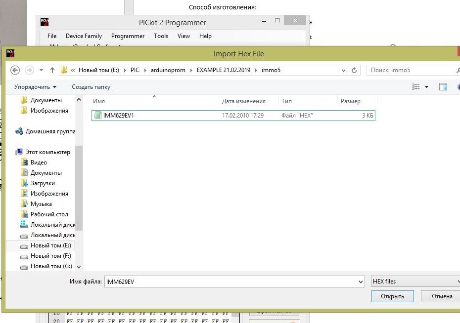
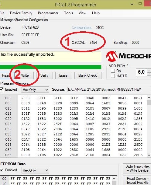
Our Hex file is loaded into the program. We are convinced that
1. the calibration constant has not changed;
2. Click Write.
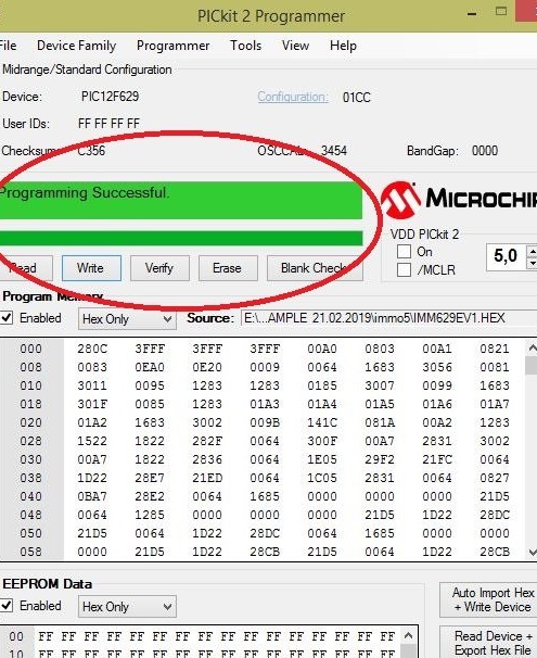
The program will be loaded into the microcontroller, it will be verified and, if everything is fine, the message Programming Successful will appear and the windows will turn green. Otherwise, the windows will be red, you will need to erase the program in the microcontroller (Erase) and program again.
The immobilizer should be invisible, these are exactly what I do without boards. I will show this method here:
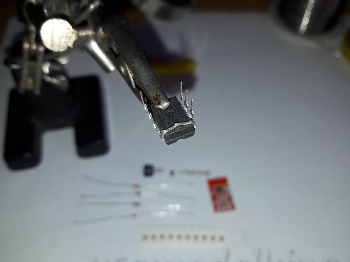
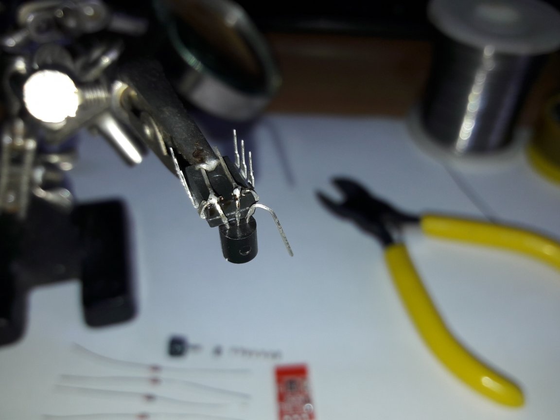
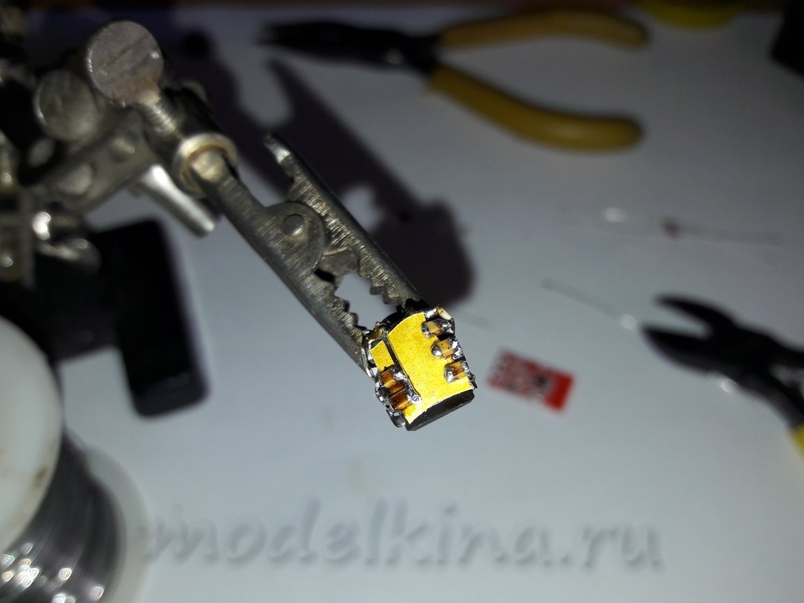
I can’t do without a third hand, I hold it with a crocodile, I bend the first and eighth legs inside the microcircuit.
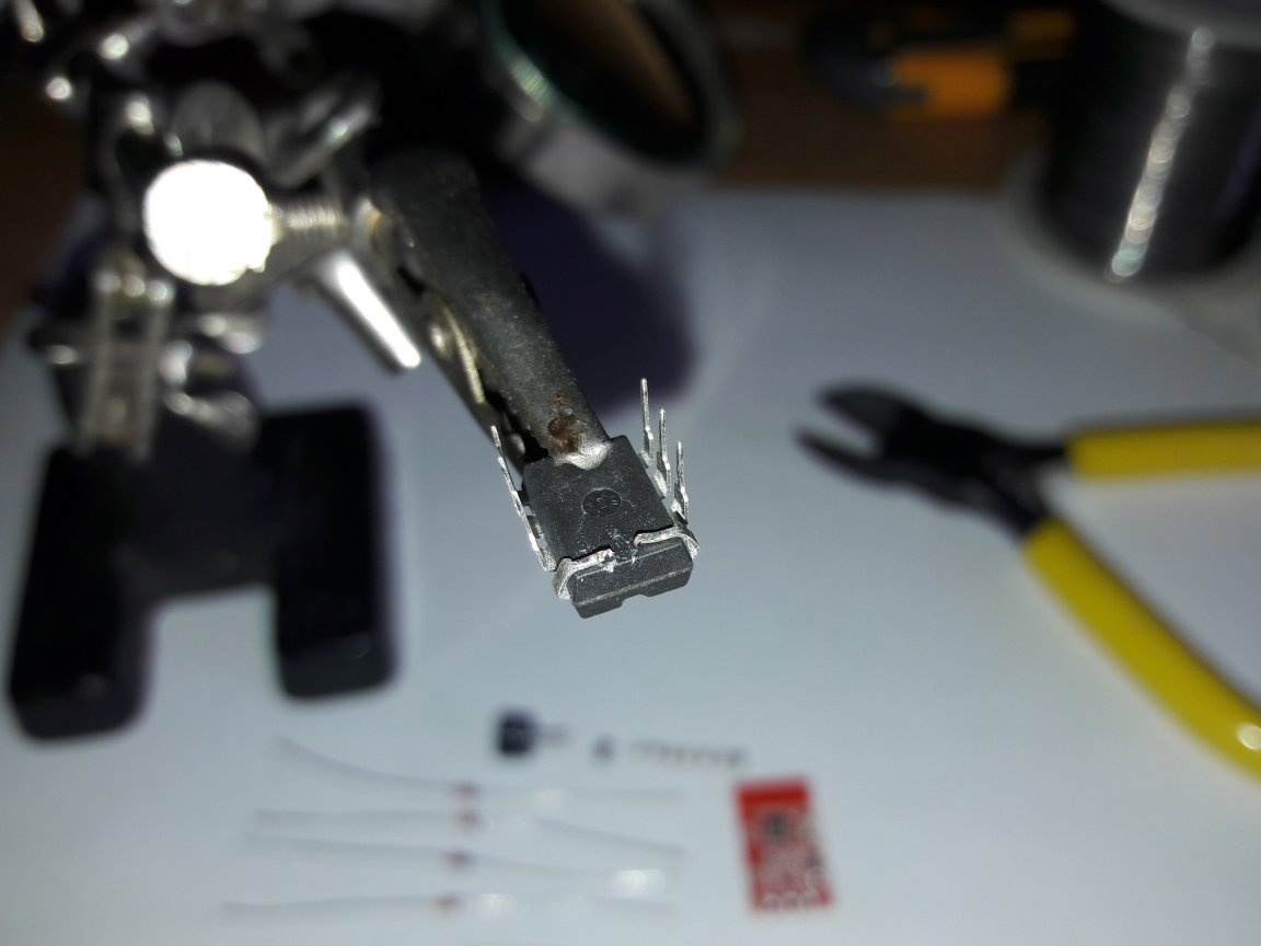
I bite off the legs along the edges so that there is a distance of at least 3 mm between them.
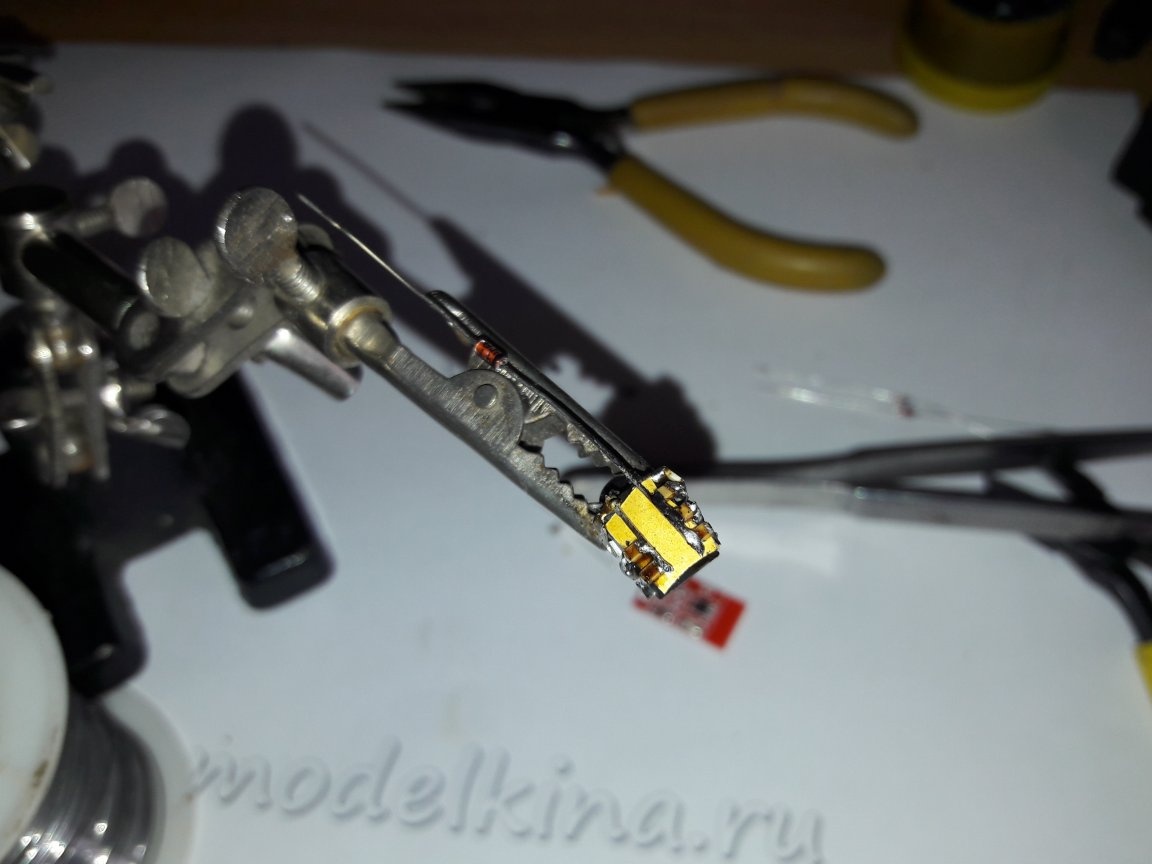
I solder the voltage stabilizer 78L05, the 1st leg of the stabilizer to the 1st leg of the microcontroller, the 2nd leg of the stabilizer to the 8th leg of the microcontroller according to the diagram.
View from above.
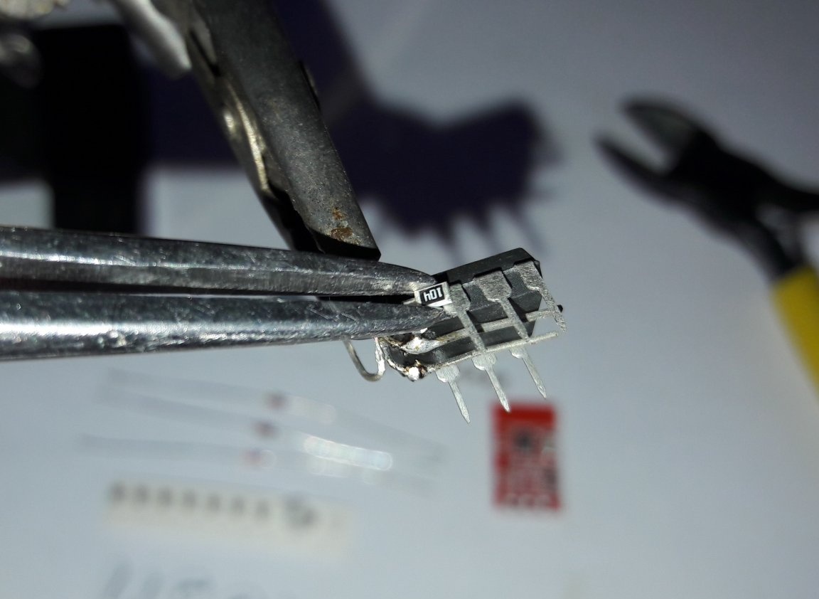
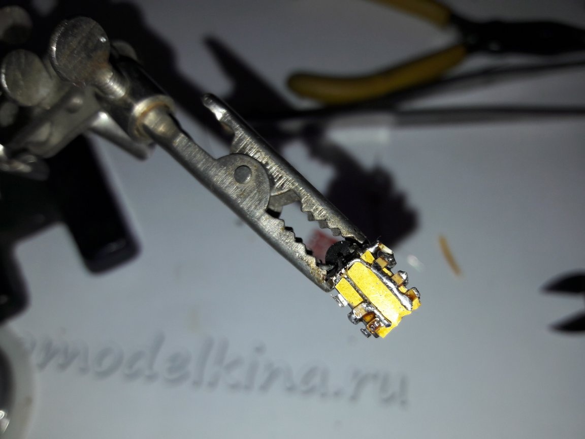
Then, according to the scheme, the resistance of 100kOhm of the legs 2, 3, 4, 5, 6 of the microcontroller to + 5V is soldered.
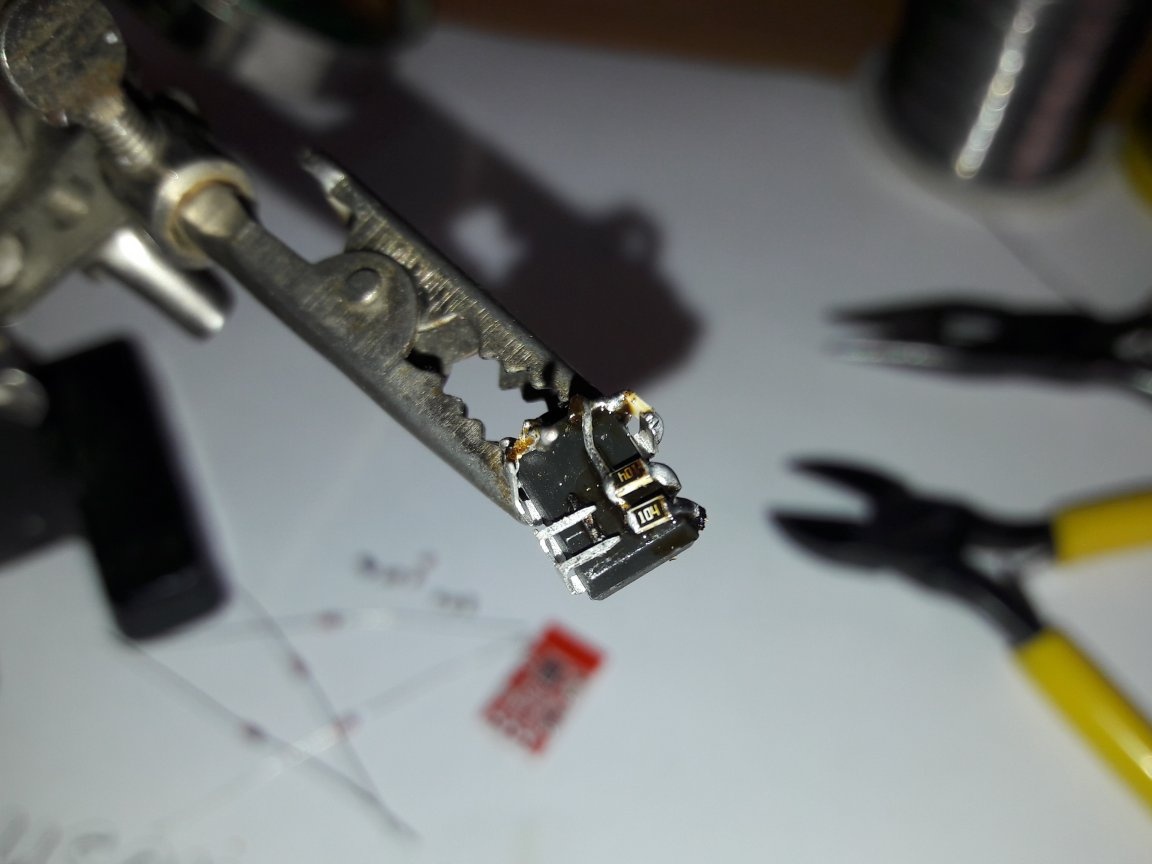
Here the negative contact must be temporarily bent back.
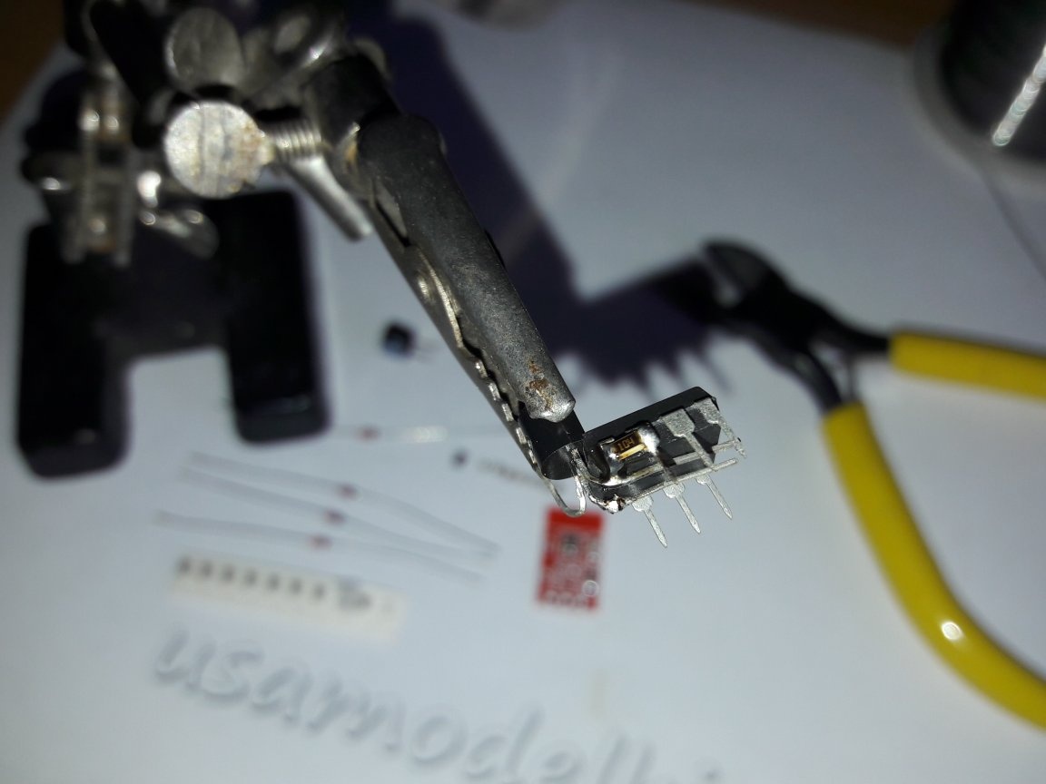
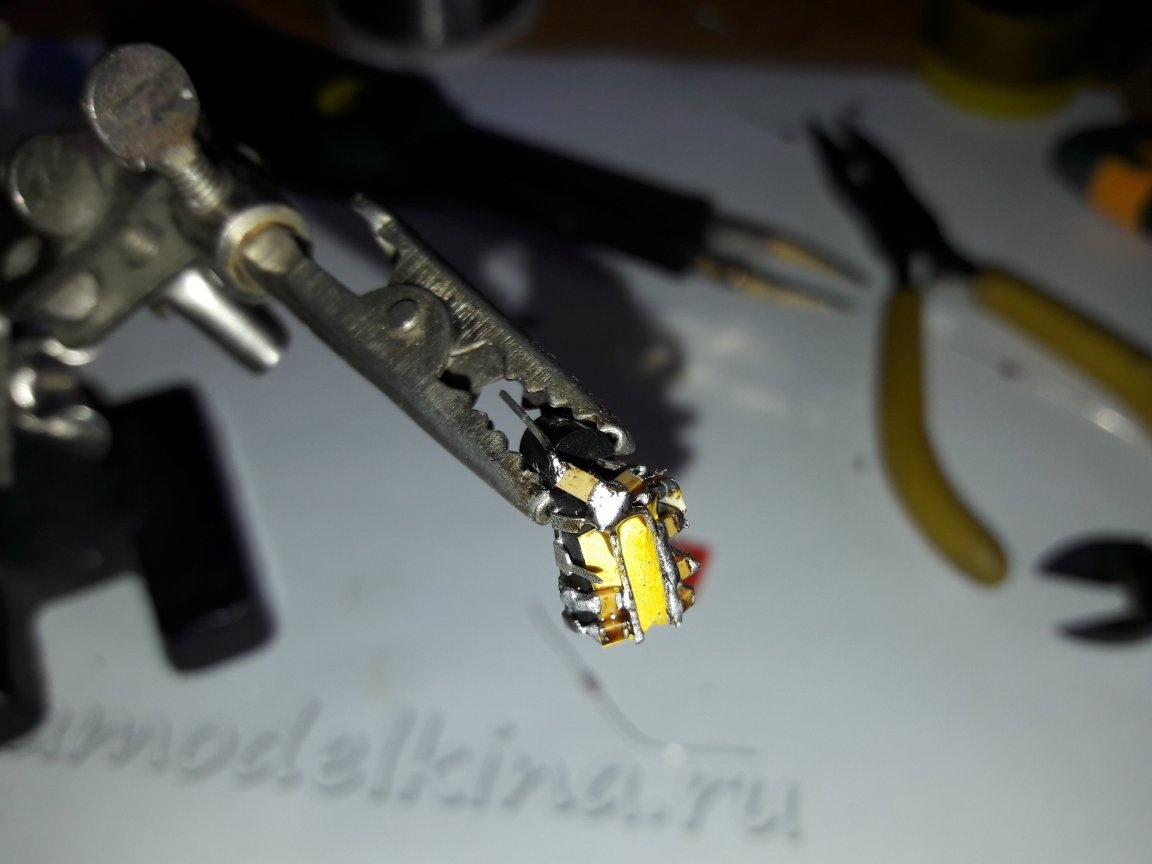
Then I use a strip of paper from double-sided tape as a dielectric.
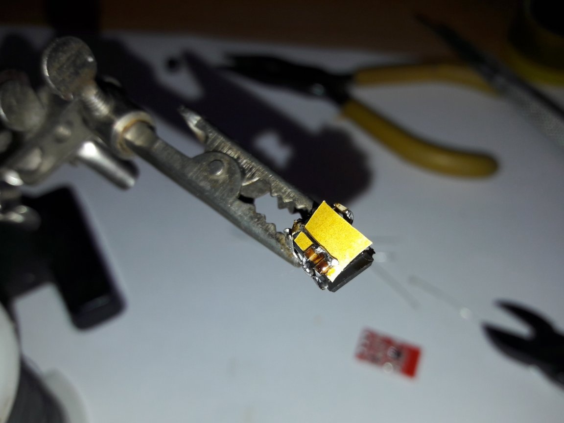
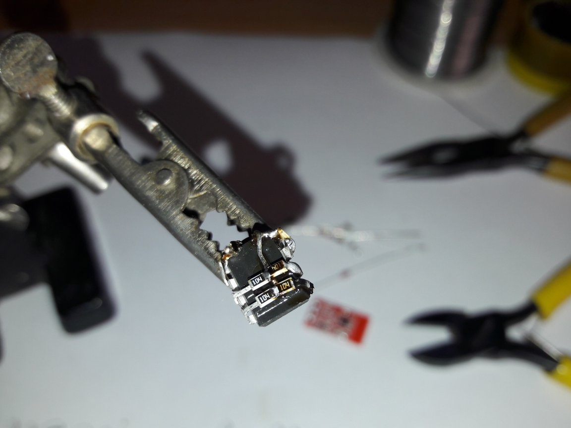
I insert a strip of this paper under the negative contact and solder the noise suppressing capacitors to the same contacts.
It turns out like this.
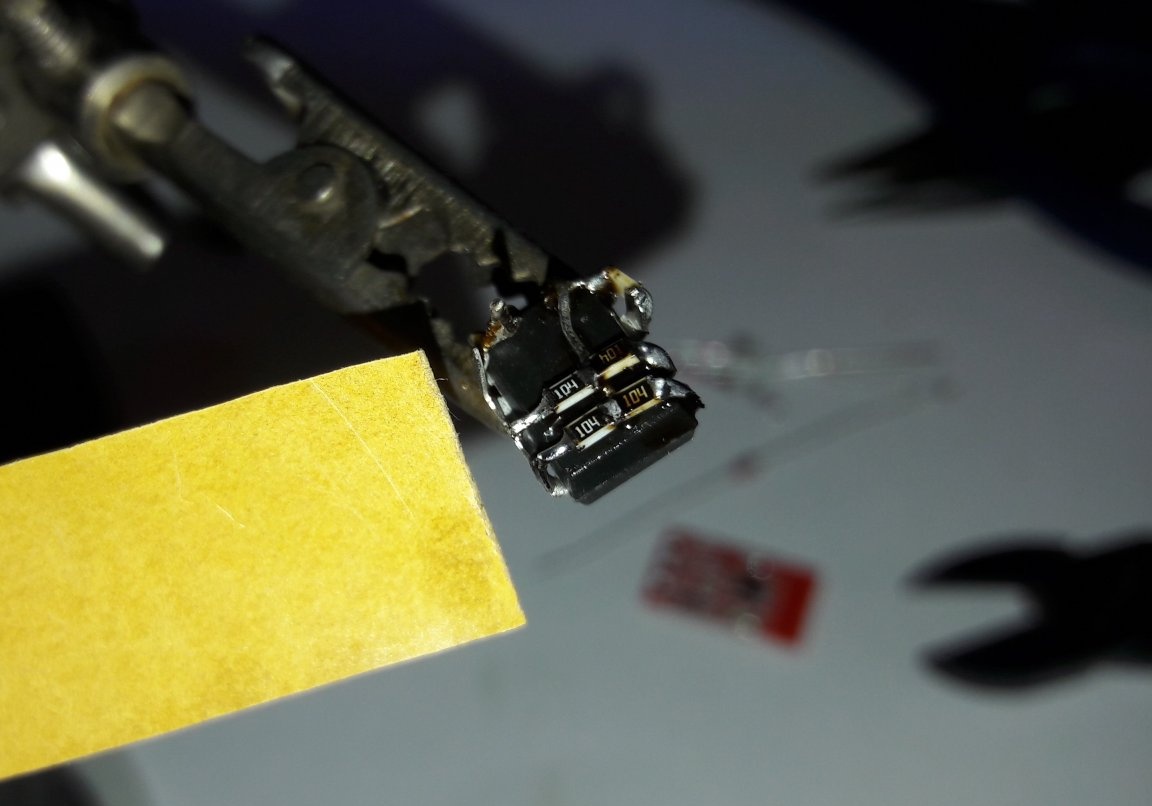
The capacitor contacts do not reach the negative, I tighten with an additional hard wire, for example, from a diode.
It should be like this.
Not very clearly visible, the next step is soldering the capacitors on the power supply to the input and output of the stabilizer.
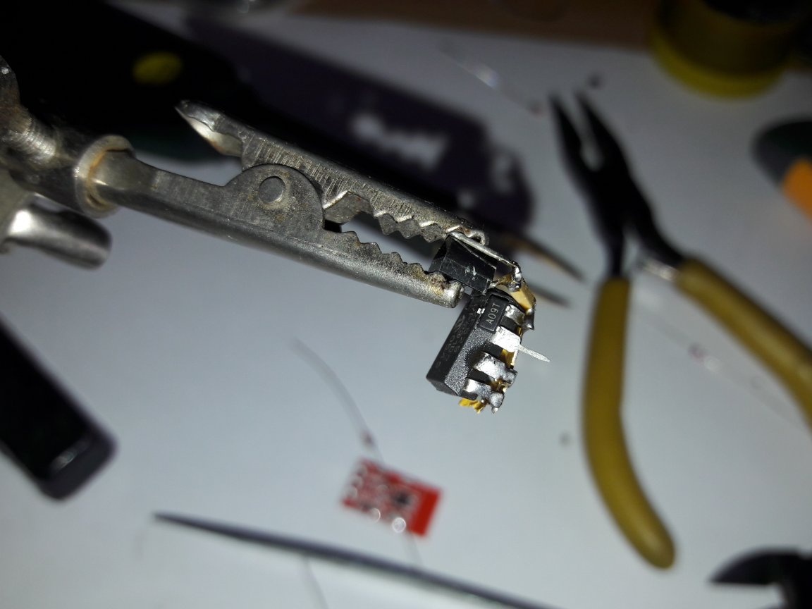
Then the transistor is soldered. A field effect transistor with a capacitive gate, and the microcontroller at the output produces no more than 5 volts, so it can be used without a resistor on the gate.
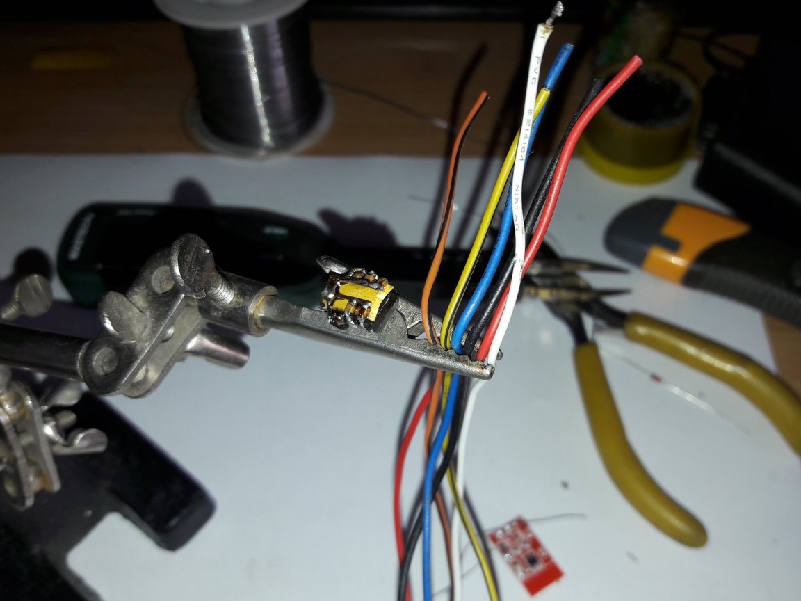
The next step, we select wires of different colors, so that later we don’t understand where which contact goes.
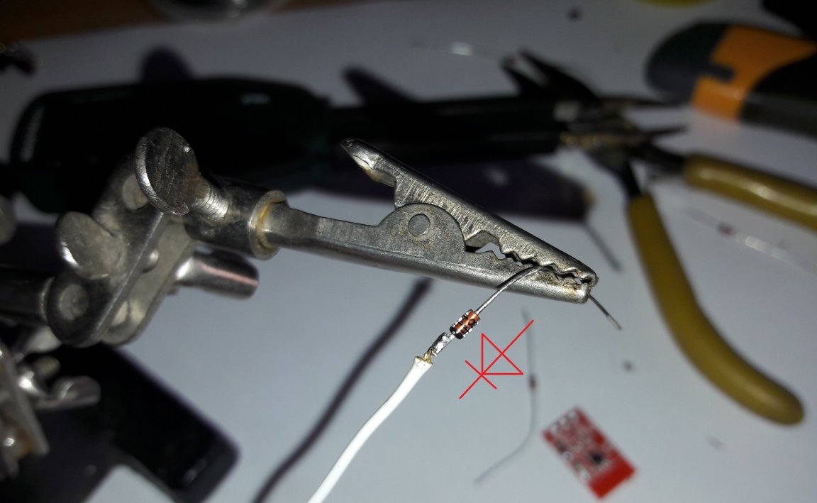
Solder the signal wires to the diodes, the black strip of the diode in the direction of the wire.
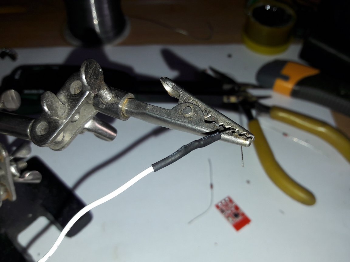
Then we put shrink cambric on the wire and heat it.
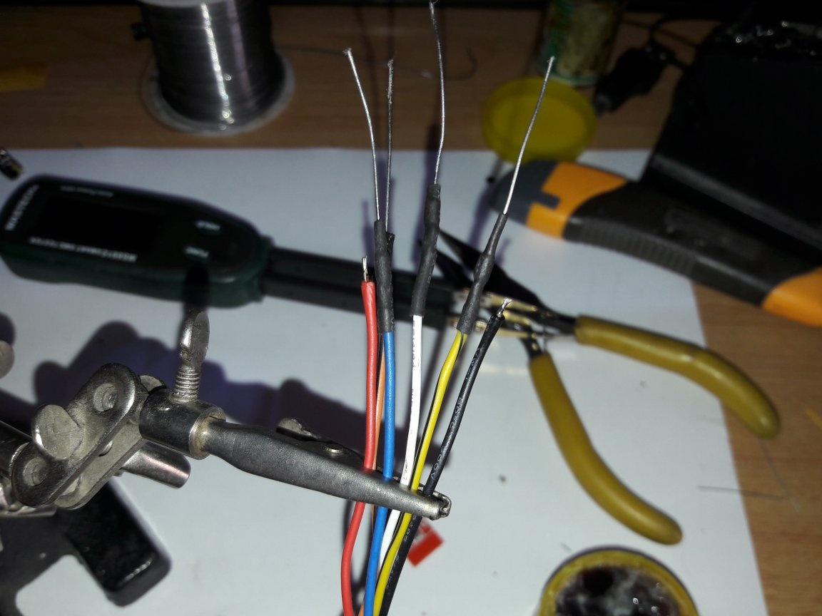
It should be like this.
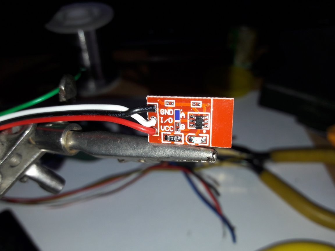
Solder the wires to the sensor, and be sure to jumper A (marked in blue).
Solder wires with diodes to the corresponding conclusions.
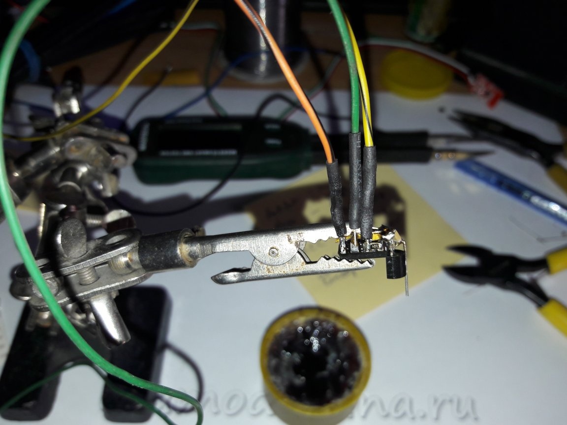
One side.
Other side.
Bend the wires in the opposite direction from the stabilizer.]
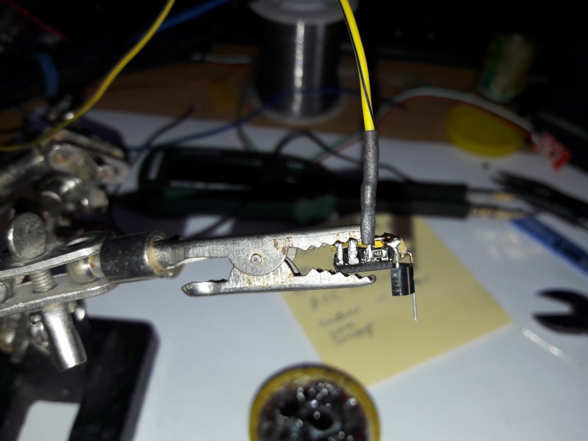
A thin multi-core MGTF wire is soldered to the output of the transistor (D-drain), it is softer and will not break the transistor leg after laying the wire in a bundle.
The + 12V power wire is soldered through the diode more powerful, the strip on the diode from the wire.
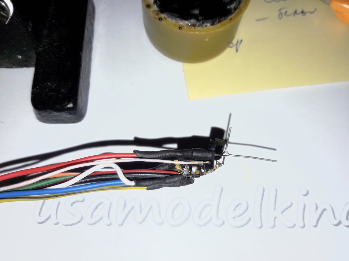
Dress shrink cambric and solder to the 3rd leg of the stabilizer.
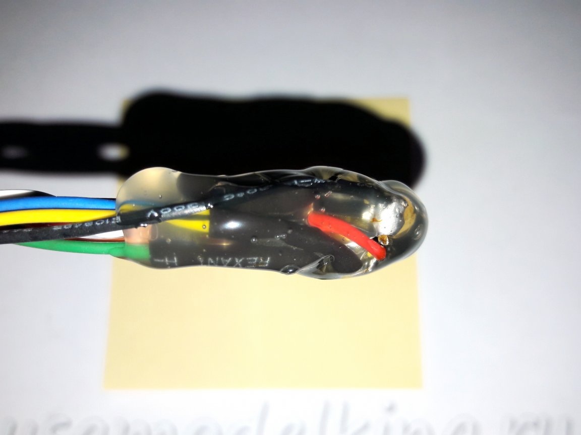
After checking all the connections, the circuit is completely filled with hot glue.
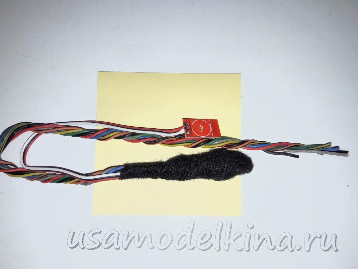
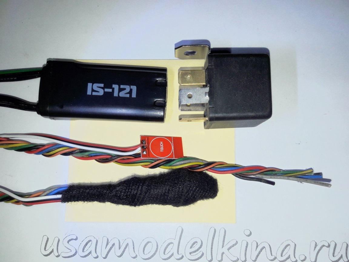
We harness the wires, the circuit can be wrapped with electrical tape or placed in an empty automobile relay housing.
For comparison, the size of the manufactured immobilizer with the size of the car relay and the relay from the Pandora alarm.
After checking the operation of the device on the table, I additionally put it in the freezer at -18 ° C for 20 minutes and then again I check everything. This is so that there are no surprises in the car. An LED is installed on the sensor board, I evaporate it, now it is not needed.
Everything is ready, you can install it on a car. I seal the sensor board with hot-melt adhesive or wide adhesive tape during installation. Places of connection, blocking and blocking method are selected for a specific car.
In Kazan and nearby cities I can help with a programmed microcontroller or install it.