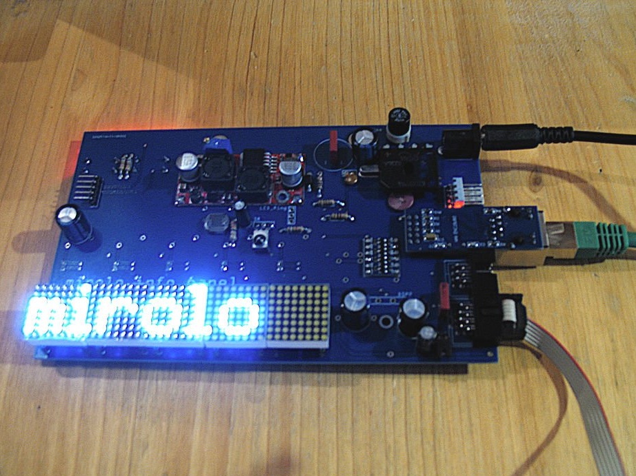
A digital display can be useful at various events to inform visitors about upcoming events, schedule changes or dynamically provide current information. Using an LED matrix for this makes messages readable even from afar.
The features of this master’s work are:
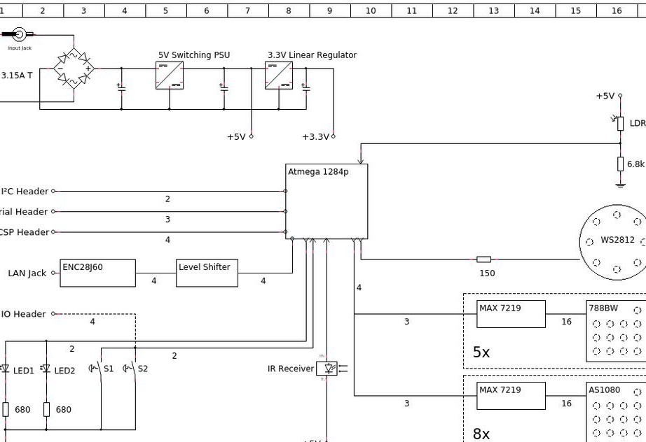
-2 lines of matrix modules, 1 indicator RGB-ring
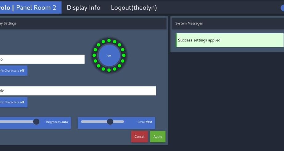
- http web interface for easy backup management
-REST / JSON API for advanced remote control
-Automatic brightness adjustment
-IR remote control
- I²C interface connector for external modules (e.g. DS1307 RTC)
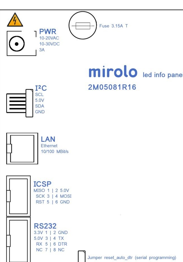
- Wide range of power consumption: 10-20 VAC / 10-30 VDC
-Ability of battery life regardless of the network
The wizard recalls that the assembly process requires some specialized tools and advanced soldering skills. Therefore, he assessed the level of difficulty as medium and not suitable for beginners.
Tools and materials:
- Soldering station with tips for soldering SMD components;
-Electric drill;
- Hot glue gun;
Reciprocating saw and metal saw blades;
-Pliers;
-Screwdriver;
-Spanners;
-Multimeter;
-Set of taps and dies for threading;
- Countersinks;
-A screwdriver;
- Hacksaw for metal;
- Two-component glue;
-Sandpaper;
-File;
-Double-sided tape;
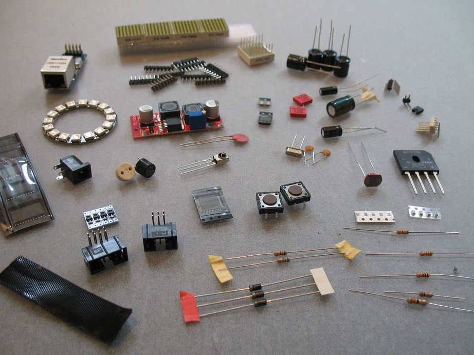
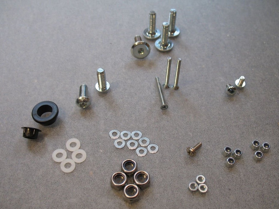
A list of parts necessary for the manufacture of this device, the master, gives a separate file. The list is extensive, and so as not to confuse anything, it will be laid out in the same way as the master.
Parts List.
When purchasing components such as electrolytic capacitors, it is important to ensure that their height does not exceed 12 mm. Otherwise, they will be higher than the matrix display, and the board will not fit properly.
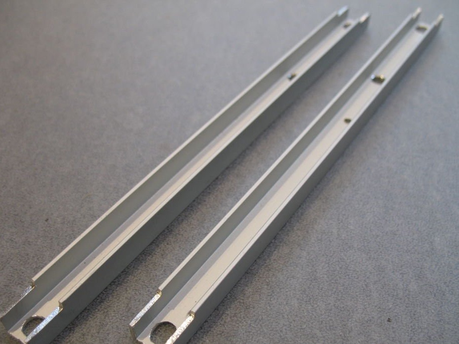
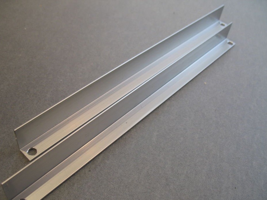
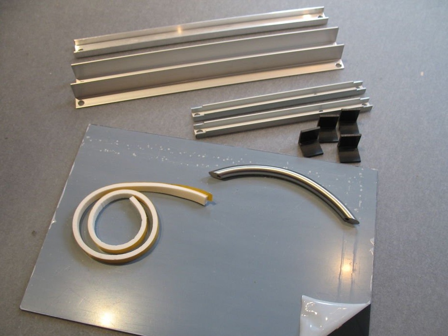
Step One: Preparing Parts
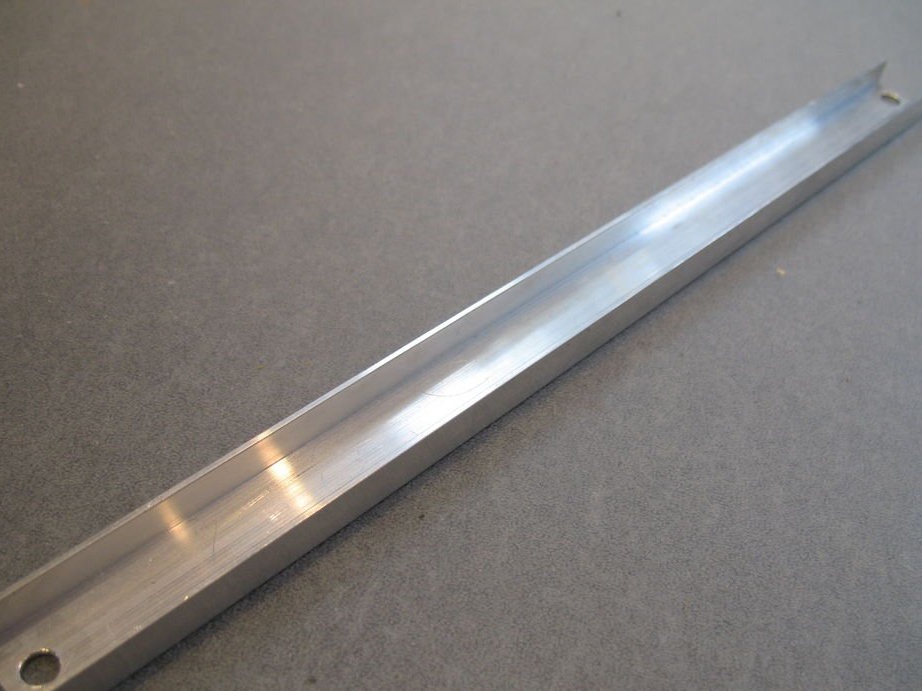
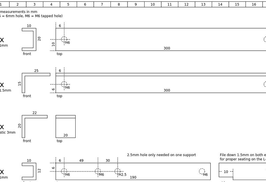
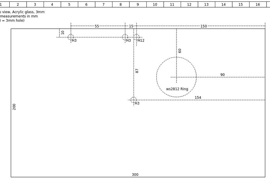
According to the drawings, prepares details for the frame. Drawings can be downloaded here.

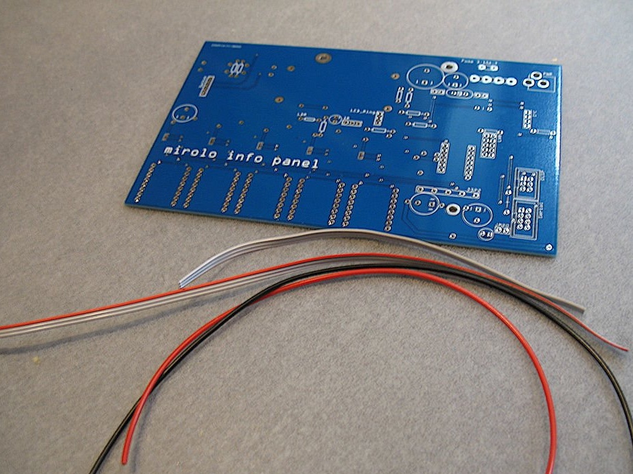
Step Two: electronic part
As for printed circuit boards, the master strongly recommends ordering them from the workshop. Some of the tracks are pretty thin, and it took him a few tries to get a working prototype. The circuit works fine, but the board is too complicated for home etching.
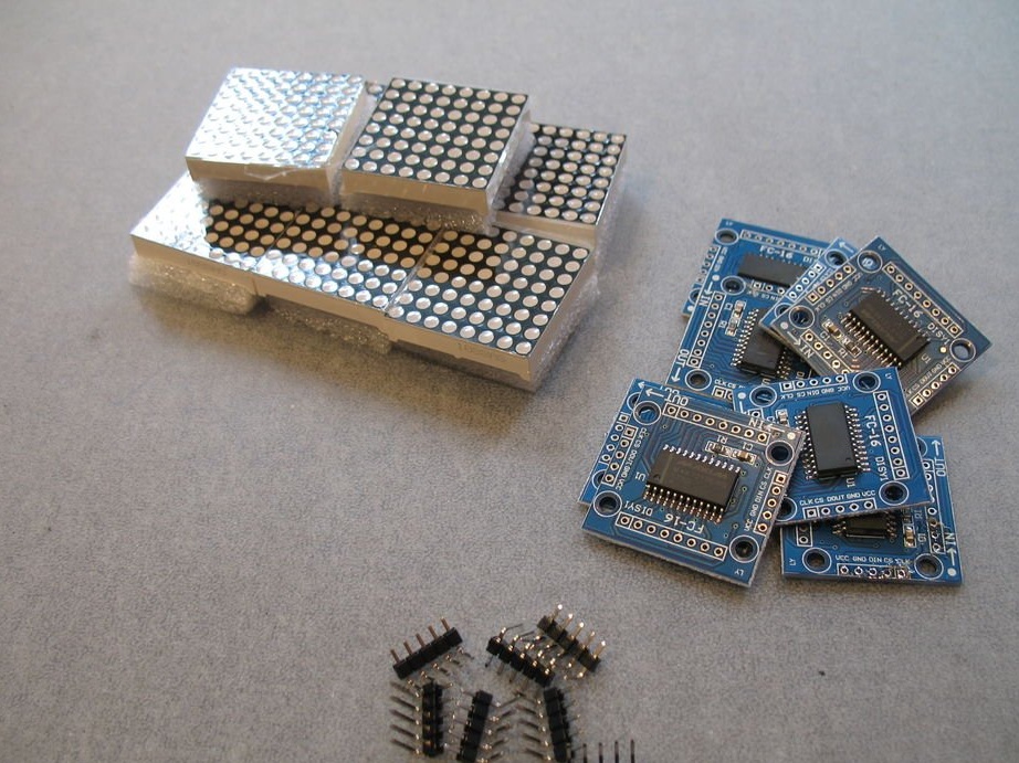
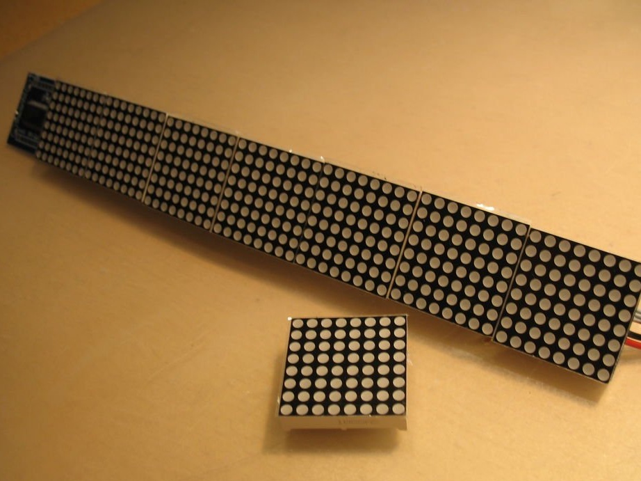
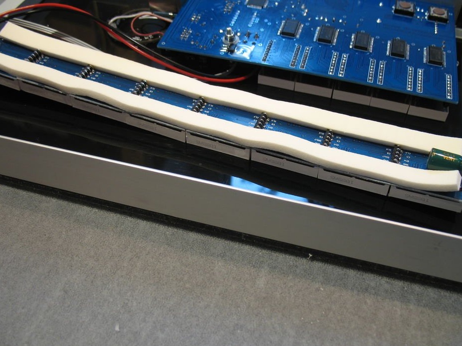
Step Three: The Matrix
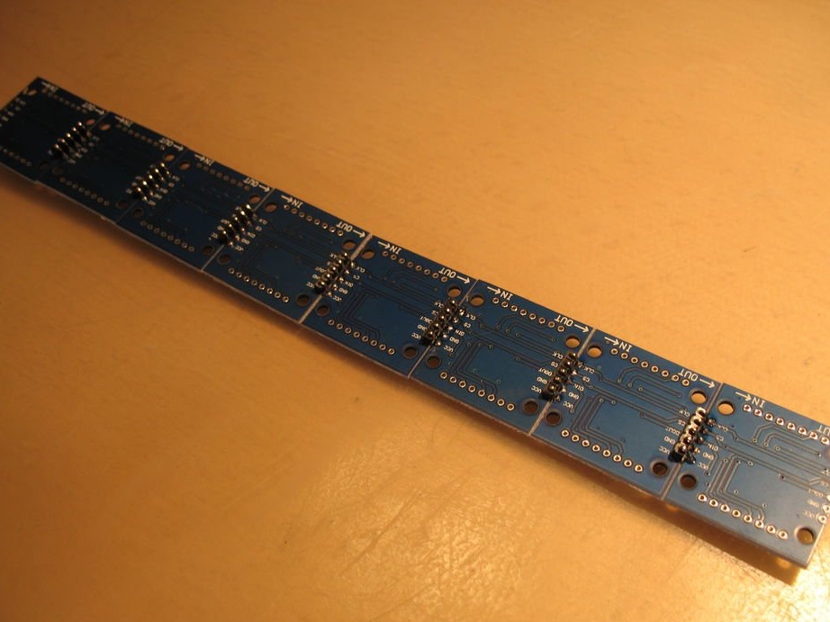
The wizard starts with the matrix. One strip consists of 8 FC-16 modules. You need to solder them together to form one line. You can use the supplied 90-pin connectors by bending them at 180 ° with pliers.
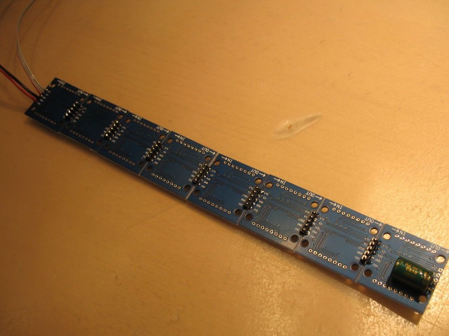
After soldering all the modules, you need to solder one of the three-pole ribbon cables to the data input, as well as two stranded wires to the power input.
Solder a 1000 uF capacitor at the output (output signal) of the strip to GND and VCC as an additional buffer.
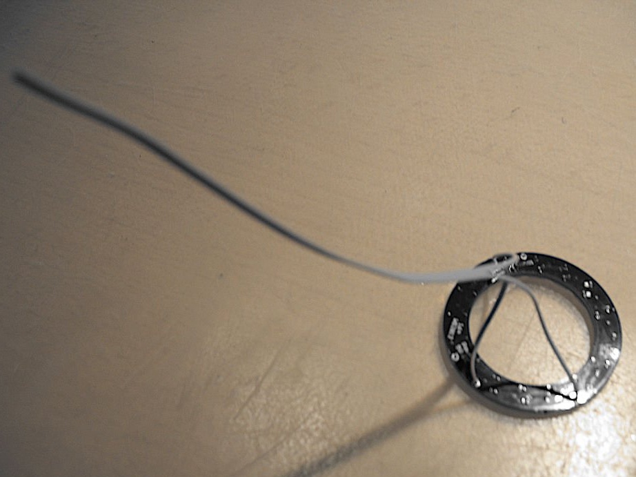
Step Four: Ring
Solder a 3-pin cable to the contacts of the LED ring.
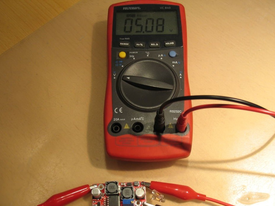
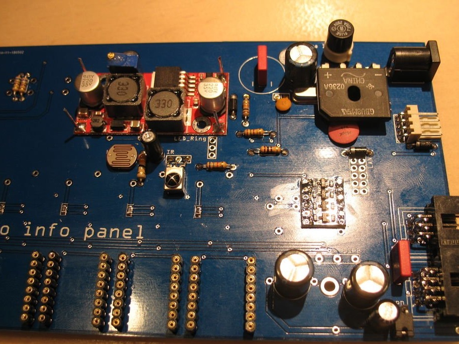
Step Five: DC / DC Converter
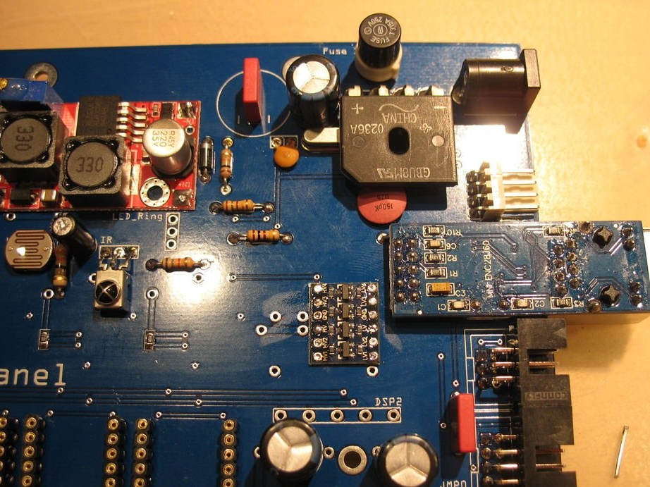
Connects the load to the inverter. It supplies 12 V power to the input. Regulates the output voltage by 5 V. After adjustment, fixes the screw of the potentiometer with glue.
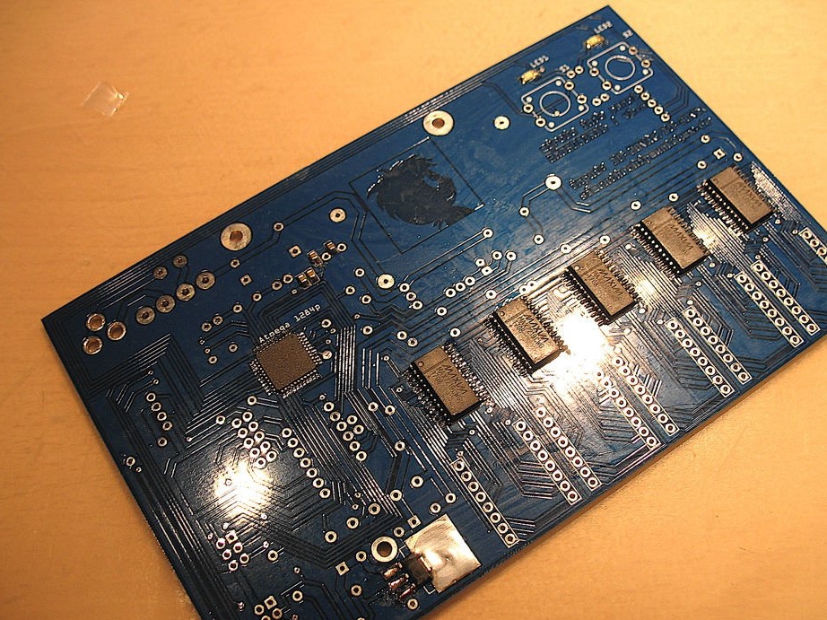
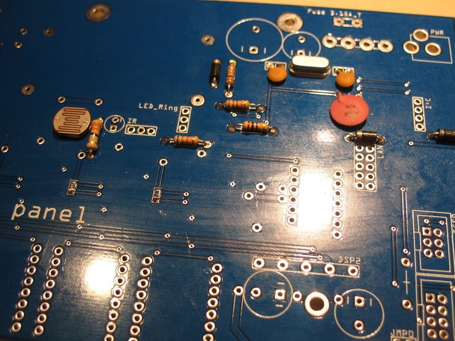
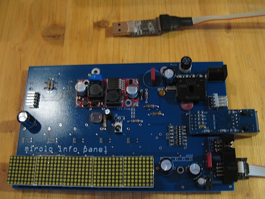
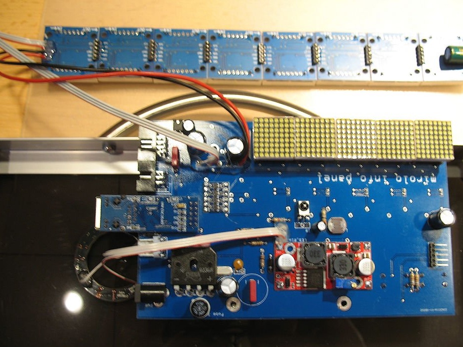
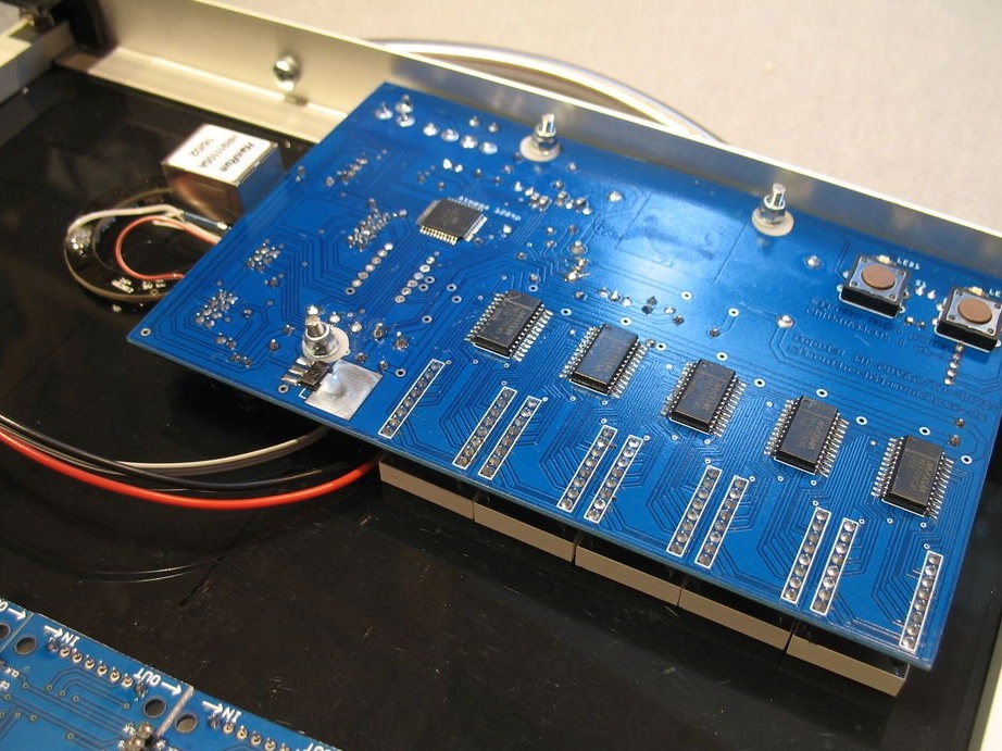
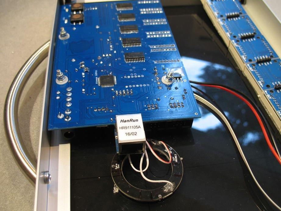
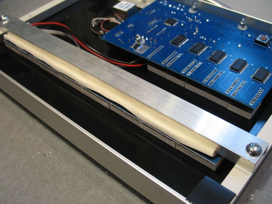
Step Six: Motherboard
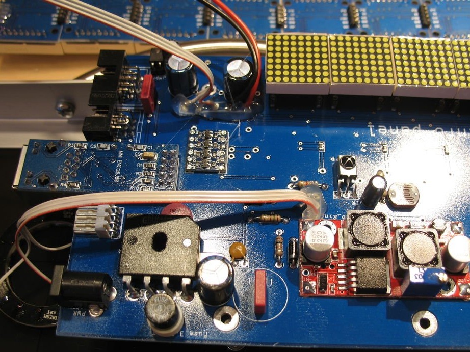
Then the master proceeds to the installation of the board. First, the master solders all the components of the SMD, including the front panel resistors and LEDs. As a rule, it is recommended that you first solder the smallest components, as this will simplify the soldering.

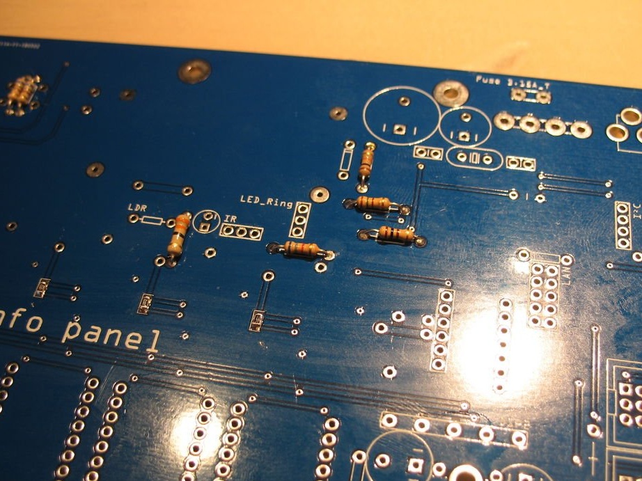
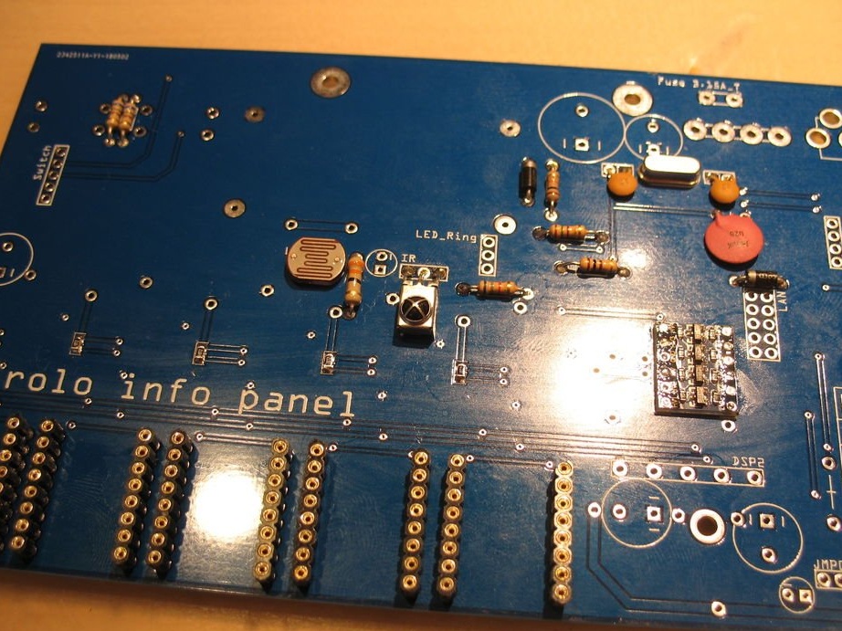
Solders resistors and small capacitors, as well as a photoresistor and an IR receiver.
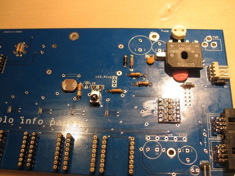
Mounts a fuse, rectifier, larger capacitors. Before mounting the DC / DC converter, on the top of the board, lay a piece of electrical tape under it to avoid short circuiting.
Mounts buttons and connectors.
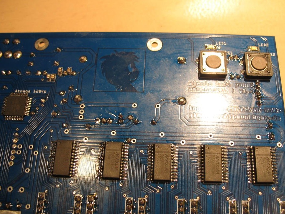
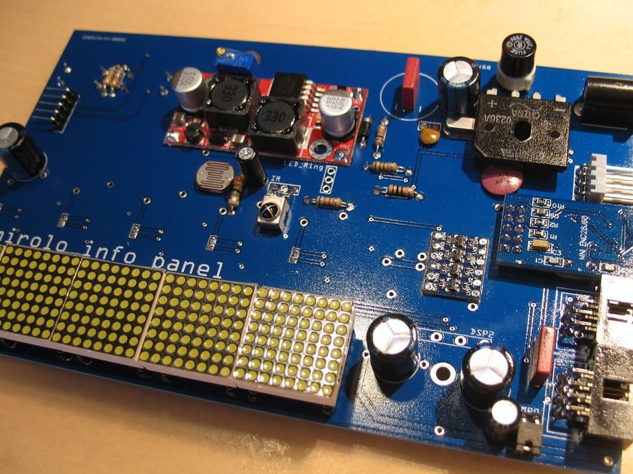
Installs LED modules.
Step Seven: Software
It connects the ICSP port to the AVR programmer and launches the Optiboot bootloader included in the mightyCore hardware library.
You can find all the software links in the file readme.
When you bootloader for the first time, an error message appears due to improper installation of some fuses. Unplug everything and try burning the bootloader again after reconnecting. Now should work without problems. If you still encounter errors, check all the connections on the motherboard again.
Do not move on until this step is complete.
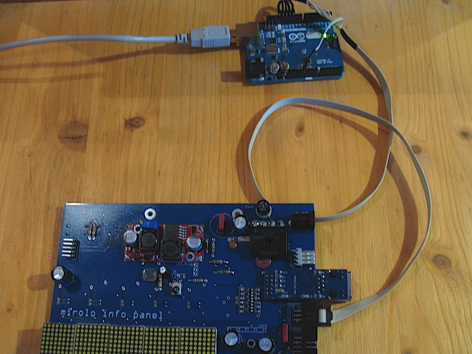
Now connects the serial port and loads the code for a fee. The serial connector pinout is designed so that it can be directly connected to the CP2102 USB module.
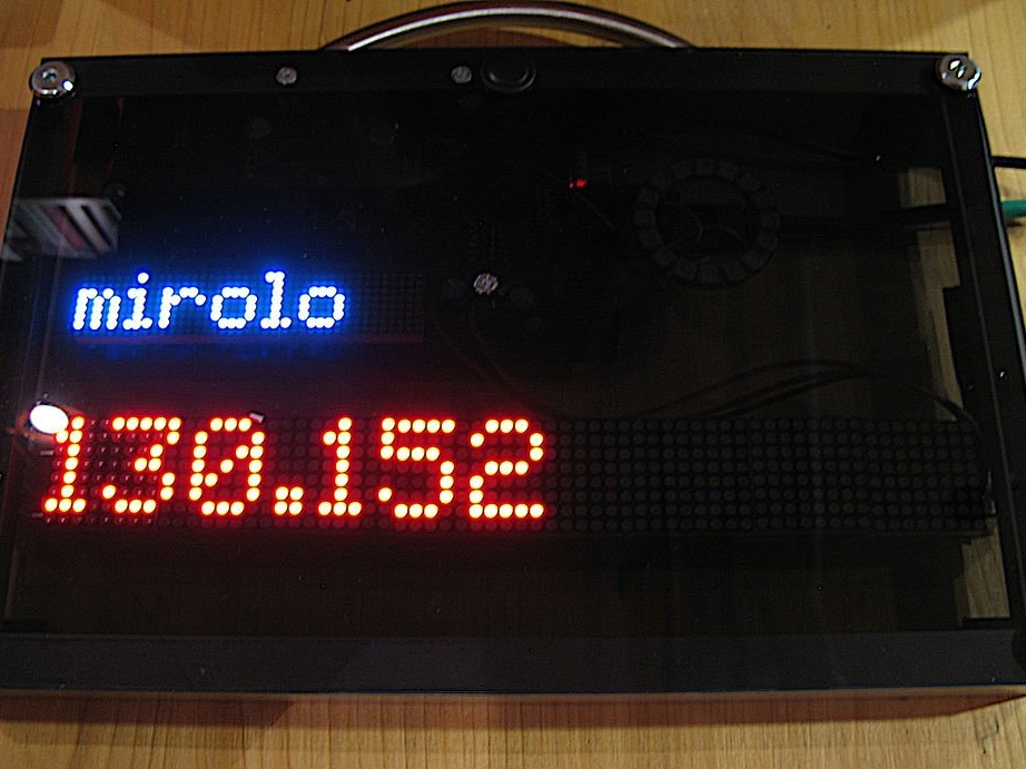
Sets LOAD_EEPROM to 0 on first boot. Otherwise, it will load random values from memory and may prevent it from starting correctly. Please note that as a result, the IP address will be set to 192.168.178.100.
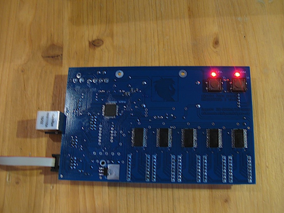
If everything is done correctly, the LEDs on the rear panel should light up.
Opens the serial monitor (115200 baud) and issues the system: reboot command. This will save all values in memory and overwrite any random values. After that, load the code again by setting LOAD_EEPROM to 1.
You can then change the IP address using a serial monitor. The display should now work.
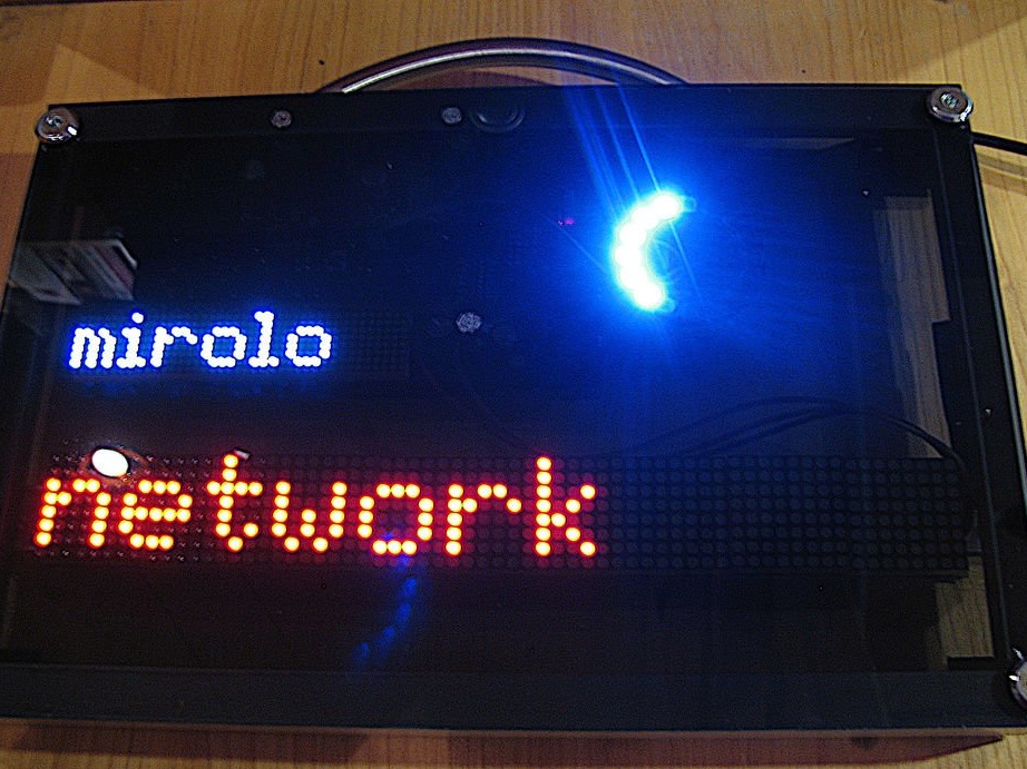
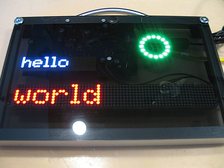
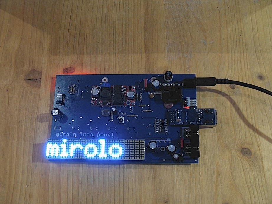
It connects a suitable power source and a greeting is displayed in the display line. You can also access the web page by entering the display IP address in a web browser. After making sure that everything works correctly, the wizard continues to work.
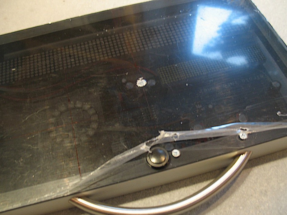
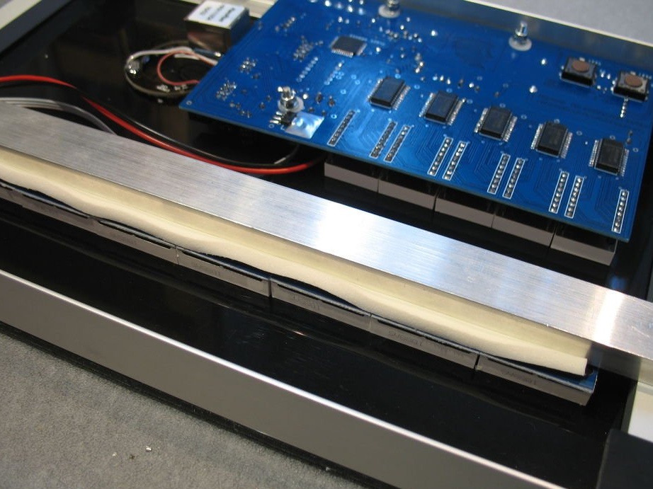
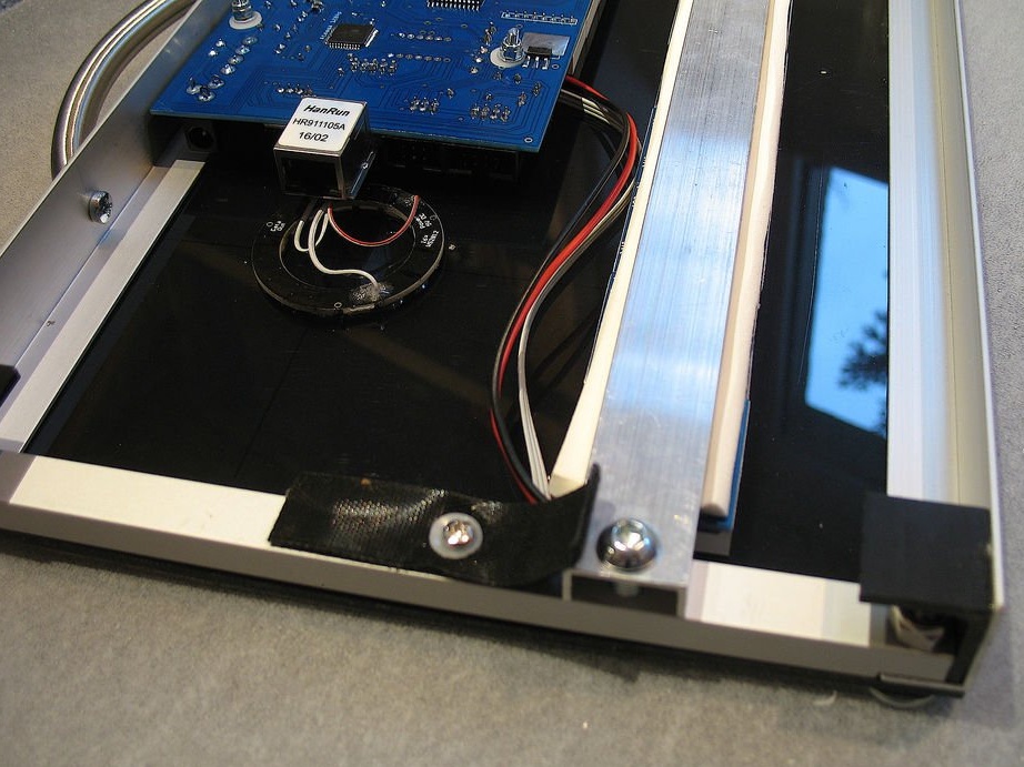
Step Eight: Build
Begins assembling the frame.
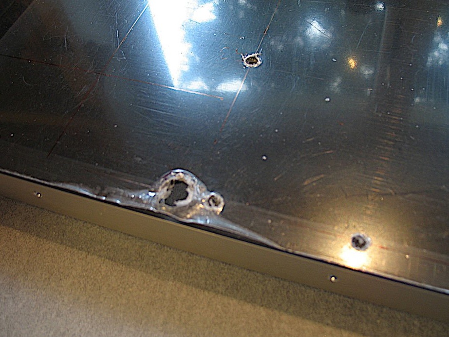
Double-sided tape sticks to a metal corner. Sticks on acrylic.
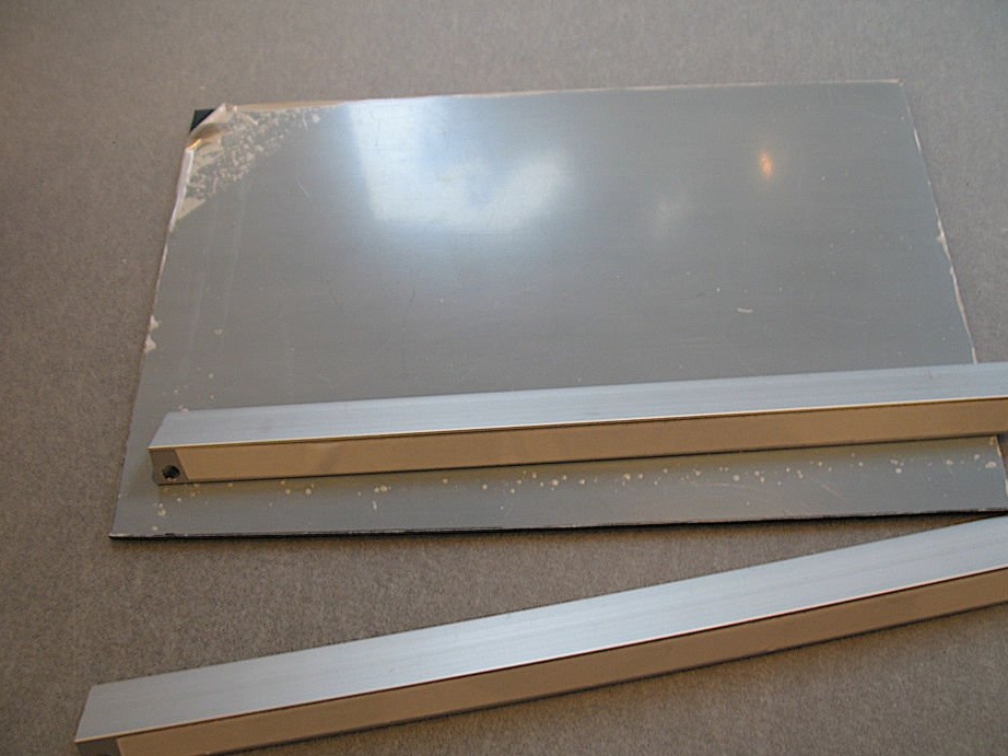
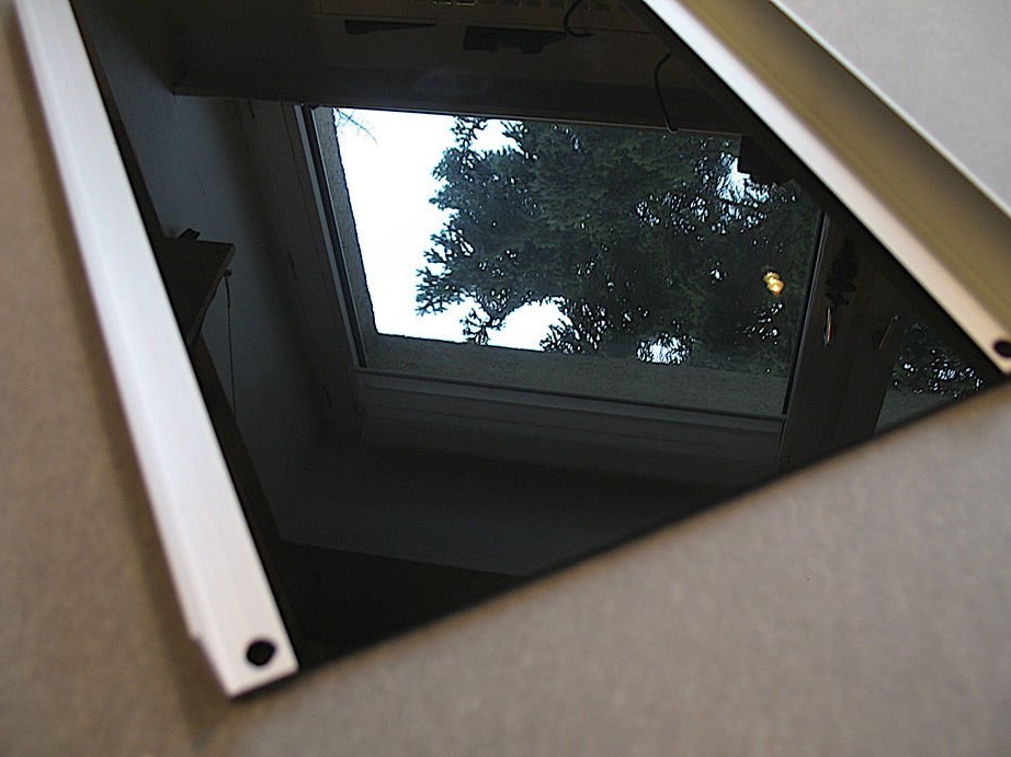
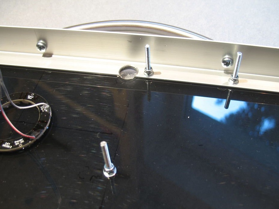
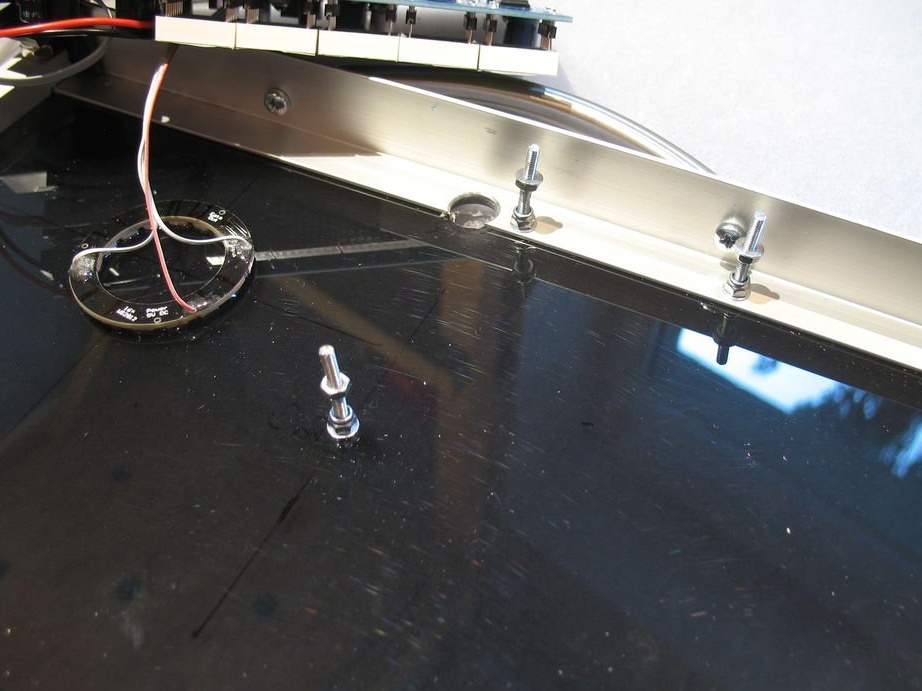
According to the drawings, marks and drills holes.
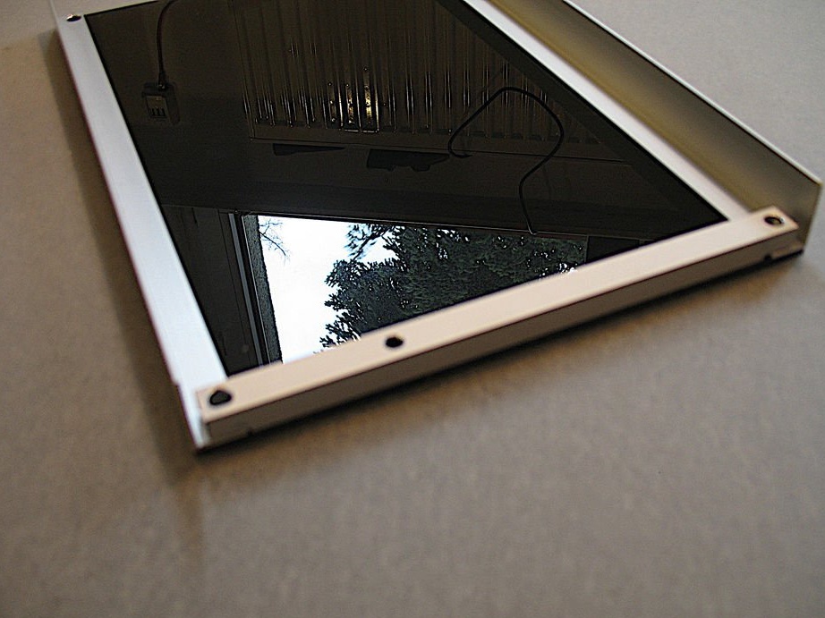
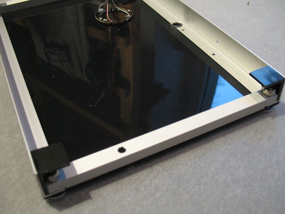
Glues 4 plastic L-profiles in the corners of the frame (they are designed to mount the display on the wall) and installs 3 screws with nuts and washers for mounting the printed circuit board.
Glues the LED ring.
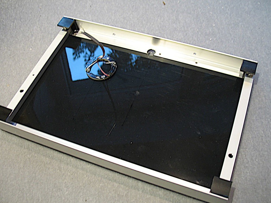
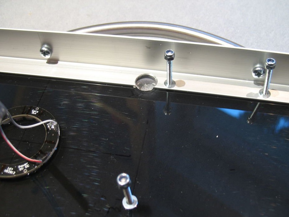
Screws the board, connects the connectors.
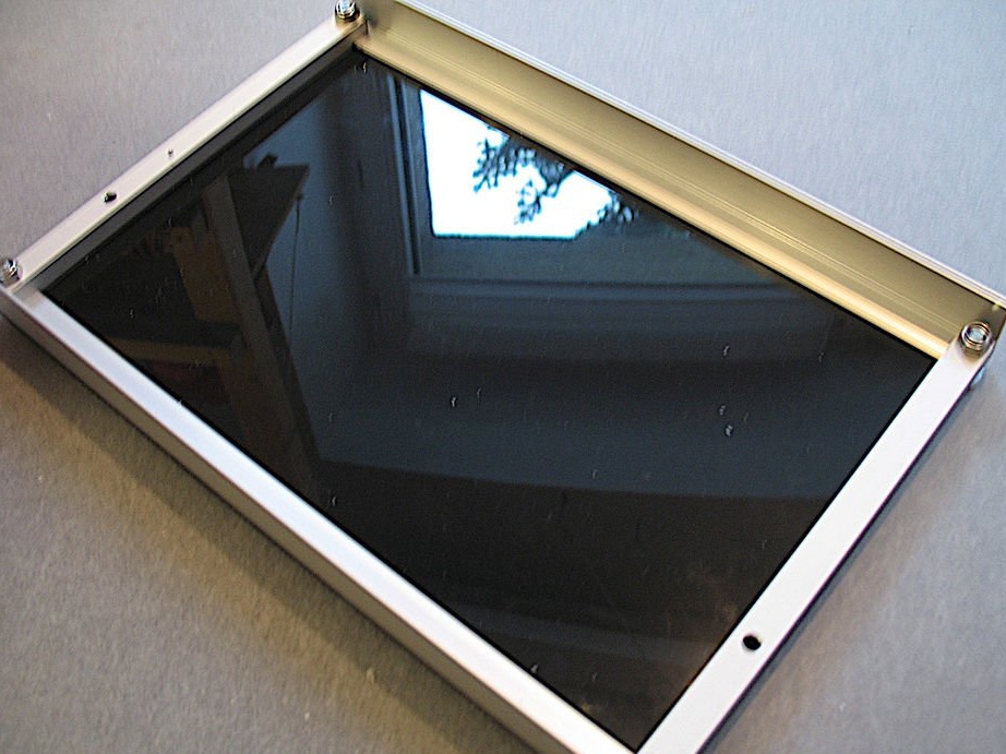
Fixes the bottom LED matrix.
Now it remains to remove the protective film from acrylic.