The master was on the verge of buying a small desktop vice, but then he thought: since they will not be used for difficult tasks, why not build them yourself and save on the purchase? Therefore, this homemade, this is what the master was able to come up with cheap materials that he had on hand.
Materials:
- pine timber;
- PVA glue;
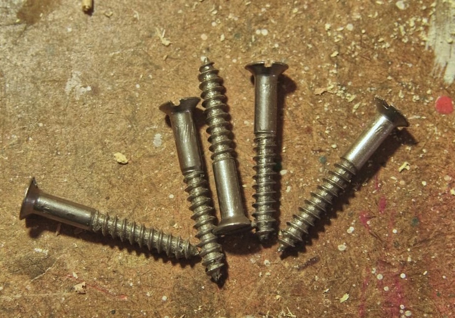
- screws 45 mm;
- screwed up;
- T-shaped nut;
- adjusting screw 6 mm x 30 mm;
- adjusting screw 6x75 mm;
- screws 3 x 25 mm;
- nuts;
Instruments:
- saw;
- drill;
- pen drill 19 mm;
- drills 3, 3.5, 8 mm;
Step 1: The main idea
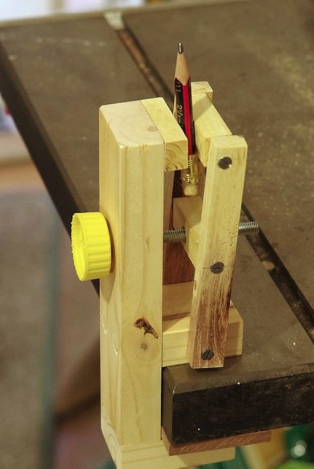
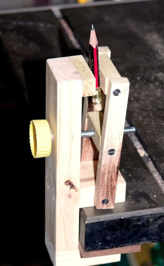
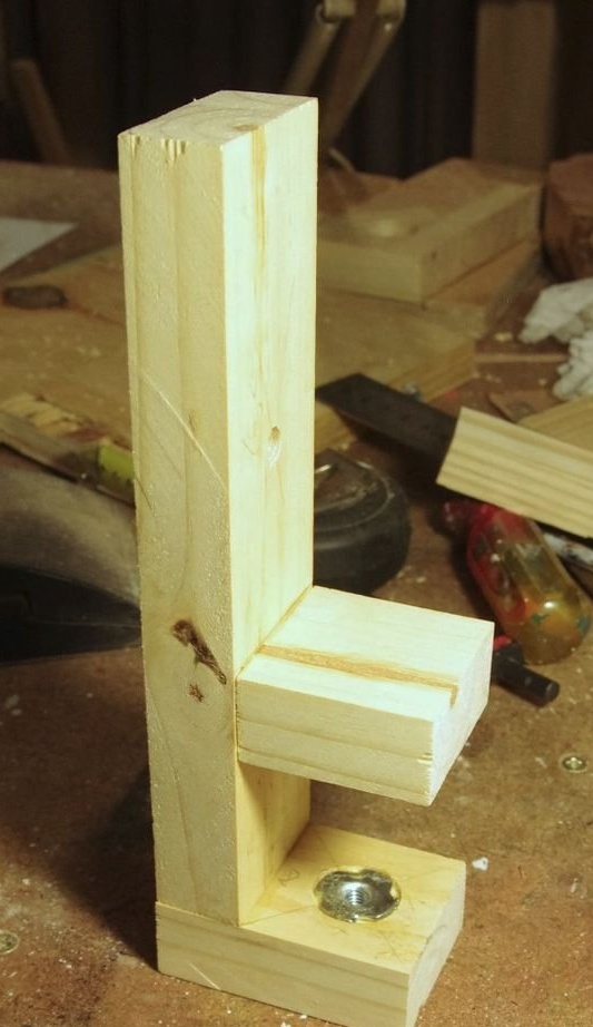
The first image shows how the vise works. The main frame with a fixed sponge at the top is attached to the desktop, and the other sponge is mounted on parallel levers, which can be adjusted using the adjusting screw to open and close the jaws.
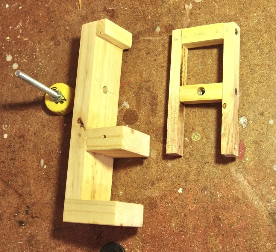
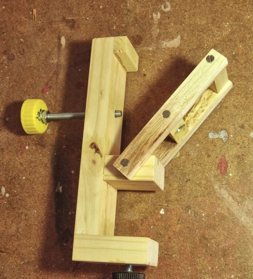
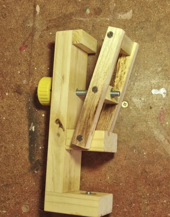
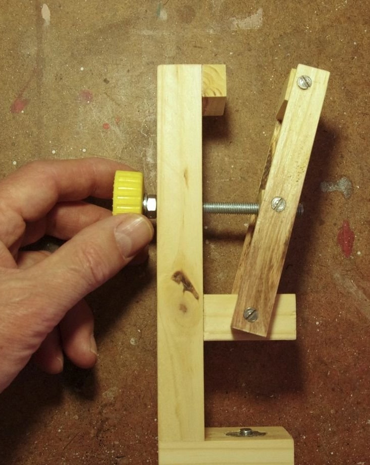
The second figure shows the main parts before final assembly. The third figure shows the adjustment levers attached to the main frame, and the fourth figure shows the adjustment screw. The last figure shows the movement of the jaws that are closed / opened by turning the adjusting screw.
The advantage of this design is that it has a small area. The bottom line is that the movable sponge moves along an arc that changes its height and angle when opening / closing. While it is not too wide, a change in height is not a problem. The solution for changing the angle is to allow the sponge to rotate between the attachment points. Then the angle is automatically adjusted when you clamp something between the jaws.
Of course, the strength of the vise depends on the materials used. If you just want to firmly hold a thing from soft material, then the tree will do the job. But, if it is metal, then the vice should have impressive durability.
The master used a block of pine (soft wood) for the main frame, and for sponges and adjusting levers he used solid wood.
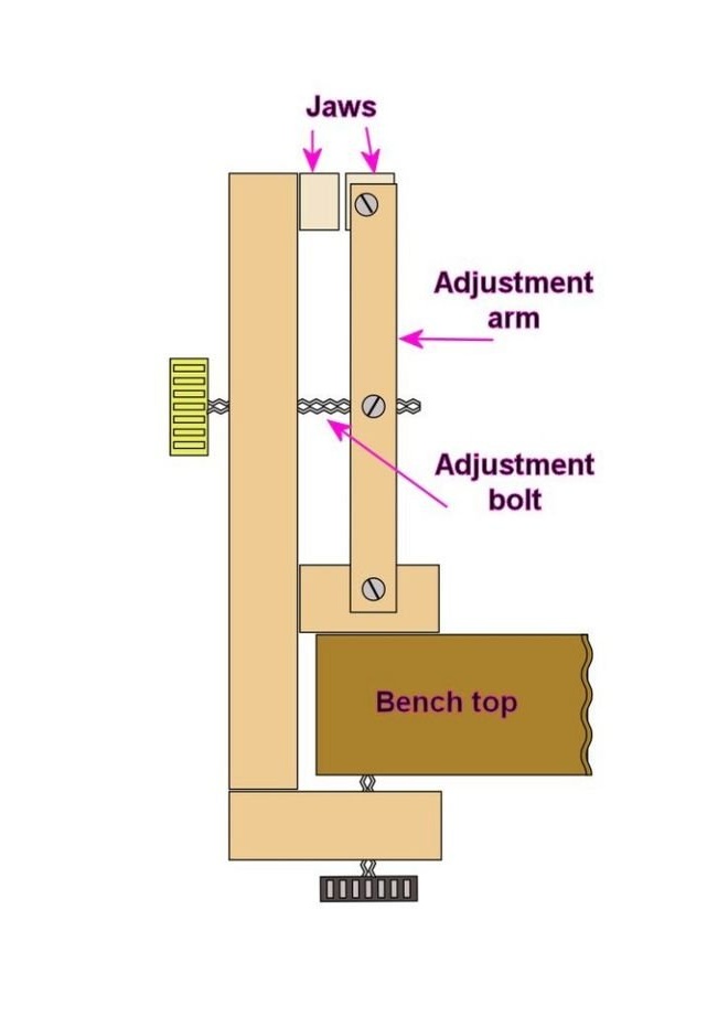
Step 2: Dimensions
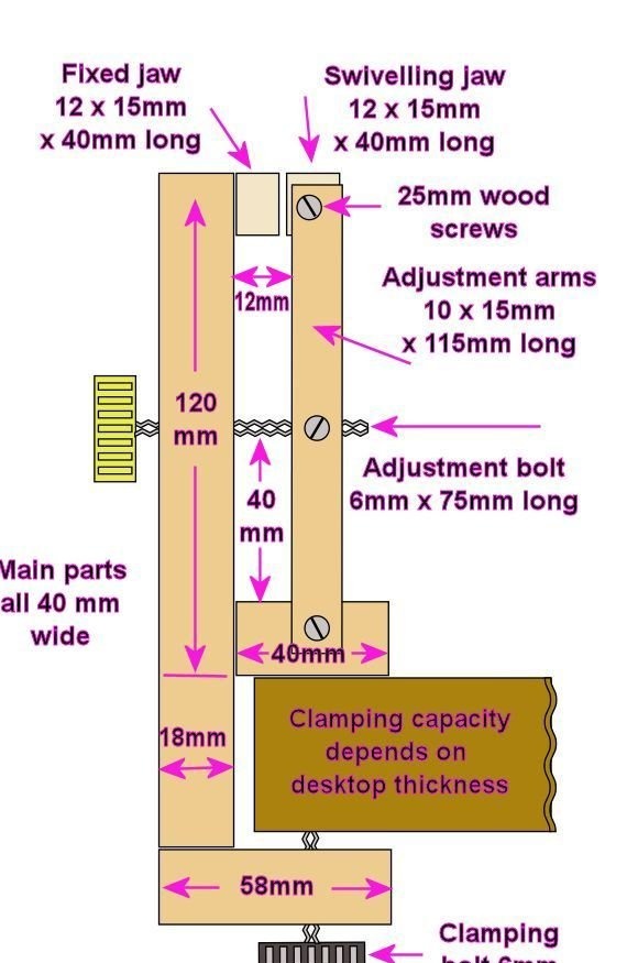
The figure shows all the main dimensions on the basis of which the vise was made. Of course, the size can be adapted to the needs.
All main parts have a width of 40 mm: the main frame, cams and fasteners (not visible in the figure) between the brackets for the nut in which the adjusting bolt rotates.
Step 3: Build a Vise: The Main Framework
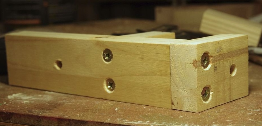
It is best to first build the basic structure shown in the first figure. The craftsman used 45mm drywall screws and white (PVA) wood glue to attach the horizontal parts to the vertical back (second image). However, later the master had to replace the screws holding the middle part with wooden pins, since the screws clogged the smaller screws holding the adjusting levers.
The distance between the two horizontal parts will depend on the thickness of the countertop. The working surface of the master has a thickness of 37 mm, so he chose a space of 42 mm.
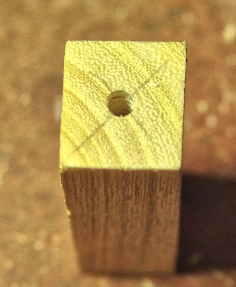
The next step is to drill holes for the clamping screw in the lower part, as well as a hole in the vertical part, in order to adjust the bolt adjustment 40 mm up from the middle part. The size in both cases was 8 mm. The lower part was provided with a T-nut, which required an 8 mm hole, and the 6 mm hole for the adjusting bolt was also 8 mm, since the bolt must fit freely to accommodate the changing angle of the adjusting levers.
Step 4: continue construction
The master made the adjusting levers, cams and fittings holding the nut for the adjusting bolt from solid wood, since they are all load-bearing parts.
The swivel sponge and fasteners for the adjusting nut are the same size: length 15 mm x 12 mm x 40 mm. Both are secured between the adjusting levers using 3 x 25 mm screws (first image), and the same screw size is also used to secure the lower ends of the brackets to the main frame. The master drilled holes with a diameter of 3.5 mm in appropriate places on the brackets and holes with a diameter of 3 mm in the center of both sides of the rotary jaw and clamping fixtures for the nut (second image). Large openings for the main and mounting screws should allow the movement of the various parts when the jaws are open and closed.
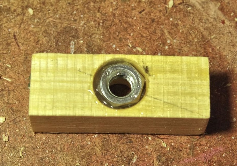
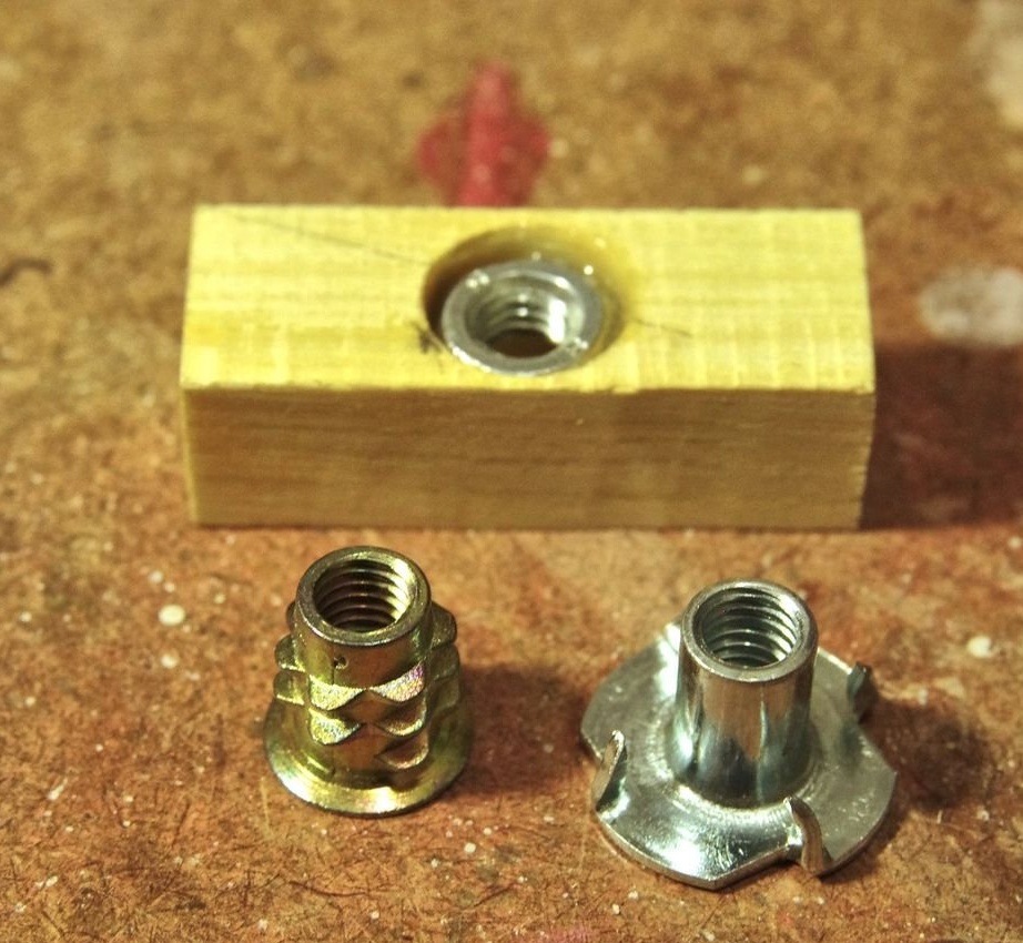
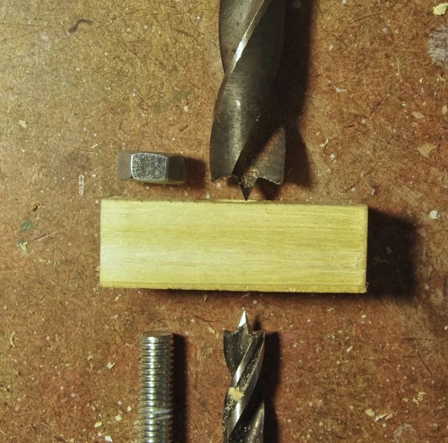
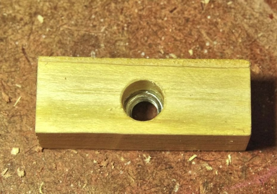
To the fasteners with the adjusting nut, you need to attach some nut (third image). The master glued a regular nut to the hole in the mount, but you can also use a T-shaped nut or threaded insert (fourth image). To fit the nut, he drilled a 12 mm hole in the upper half of the fixture into which the nut was glued, with an 8 mm hole from the bottom to accommodate the bolt, but preventing the nut from being pulled through the hole under load (the last two pictures).
Step 5: Assembling the Product
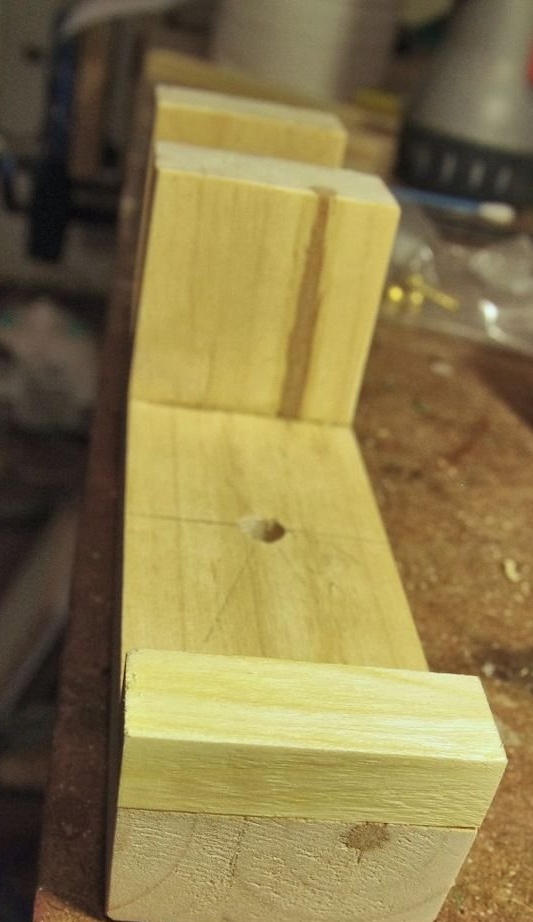
The fixed sponge can simply be glued to the top of the main frame (first image).
The movable sponge can be screwed to the brackets, but pay attention to the offset holes in the brackets (second image). This allows the sponge to protrude a few millimeters over the shoulders, and also provides a greater load on the moving arms.
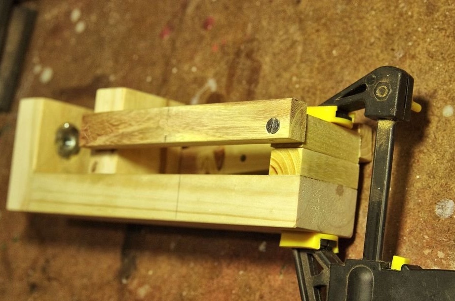
Next are the holes for fitting the lower ends of the adjusting levers to the main frame. To ensure proper alignment of the jaws, the master suggests clamping the jaws together (third image) when drilling holes. Finally, the holes for fastening the adjusting nut can be drilled in accordance with the previously drilled hole in the main frame for adjusting the bolt.
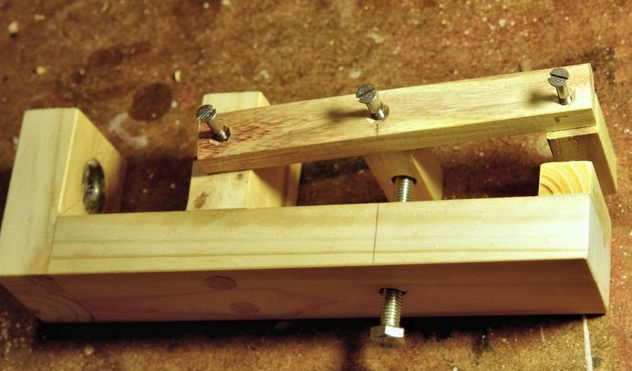
The final figure shows the holes drilled in the brackets and the screws ready for installation. They should be tight enough, but still have to allow the movement of various parts (the jaws rotate like fasteners for an adjusting nut, and, of course, the movable racks themselves turn their fixing screws below when the jaws open / close).
Step 6: Adjustment Screws
The vice has two adjustment screws: one at the bottom for attaching the vice to the top of the table, and the second at the back for opening and closing the jaws.
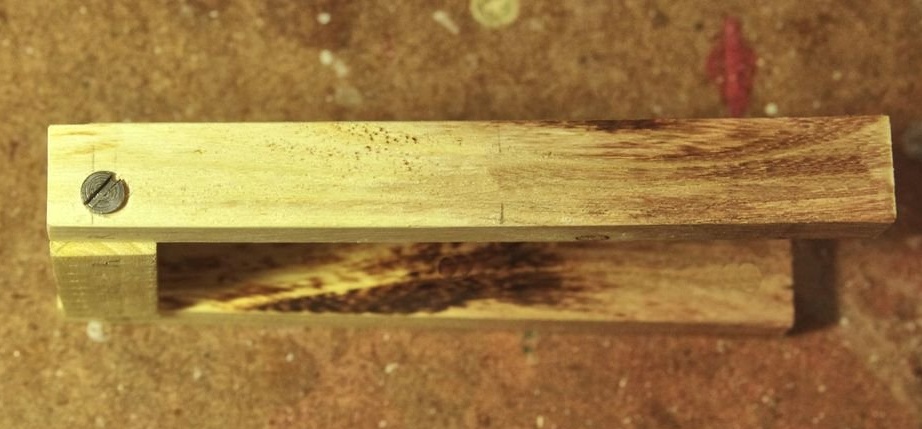
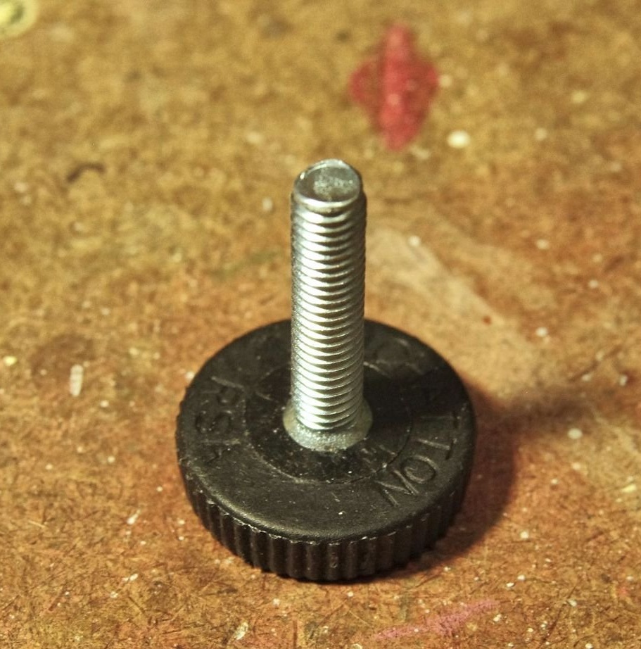
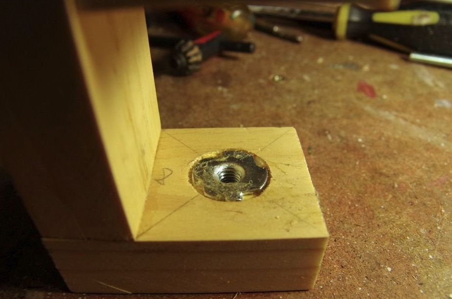
For the lower adjusting screw, the master used a screw with a plastic knob (first photo). This screw measures 6 mm x 30 mm. It goes well with 18 mm pine blocks. To place the screw, the master used a T-nut lubricated with contact adhesive before reinstalling it.First, he drilled an 8 mm screw hole and drowned the top of the nut with a 19 mm pen drill (second image).
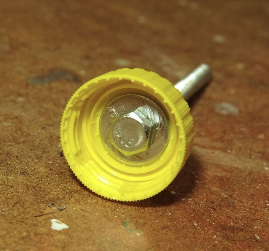
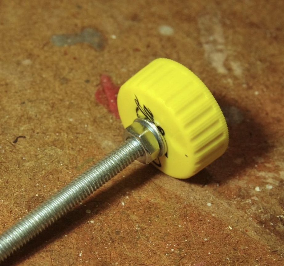
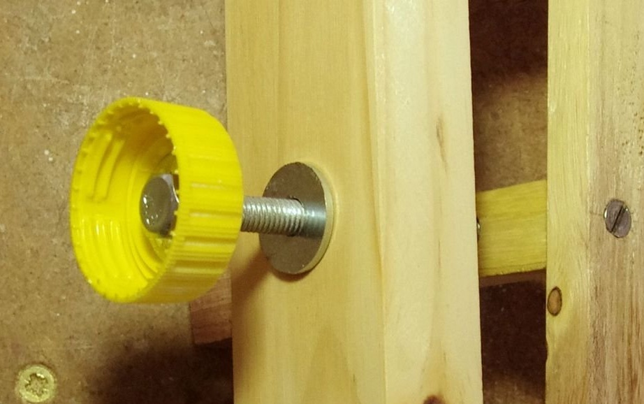
The most important adjusting screw is, of course, the one that opens and closes the jaws of the vise. A 6mm bolt, 75mm long, works great here. The handle for the bolt is made of a plastic cap from a Coca-Cola bottle. First, the master drilled a hole of 6 mm. through the middle of the cap, then pushed through a bolt equipped with washers on both sides of the cap. The locknut holds everything in place (third and fourth photo). As a locknut, the master simply damaged the thread of the bolt so that the ordinary nut was firmly fixed.
The bolt then passes through the washer (last figure) and the hole in the back of the main frame and is screwed into the nut fastener between the adjusting levers.