

Frequency measurement range ................... 10 Hz ... 60 MHz
Sensitivity (amplitude value) ... 0.2 ... 0.3V
Supply voltage ………… .7 ... 16V
Current consumption .................... no more than 50 mA.
The need for this device arose for me when it was necessary to make a master oscillator carrier for the radio transmitter and make its further configuration and coordination with other functional parts of the system. I searched for a long time on the Internet for a circuit that would work with a nokia 5110 display and would have a measurement range in which the frequency I needed fell. Finally, I accidentally found a circuit of such a frequency meter, where it was not detailed, made for another display and did not have a PCB file. But there was a firmware file. Well, now let's move on to what we need:
Expendable materials
• double-sided fiberglass foil
• M3 x 20 bolts with nuts (preferably flat hats)
• radio components (below)
Capacitors
• 10p ¬– 1,0805
• 22p - 2 0805
• 100p - 1,0805
• 10n - 2 0805
• 100n - 5,0805
• 4 ... 20p - 1 tuning
• 22uF 25V - 2 tantalum type D
Resistors
• 100 Ohms - 1,0805
• 200 Ohms - 1,0805
• 470 ohms - 2 0805
• 2.2 kOhm - 4,0805
• 3.9 kOhm - 4,0805
• 10 kOhm - 1,0805
• 18 kOhm - 1,0805
• Diode BAV99 sot23
• Choke 10 - 82 μH (I have 82 μH) 0805
• 4MHz quartz crystal
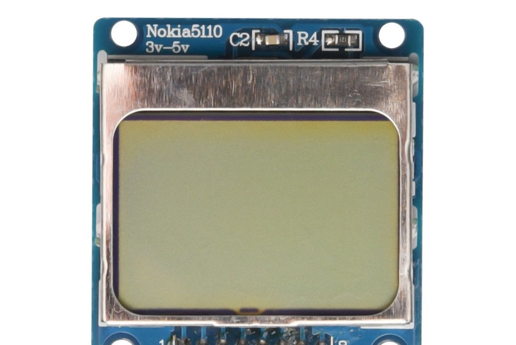
• Such a display module. Pay attention to the pinout of the conclusions (sometimes it may differ on different modules)
• Chips of stabilizers LM78L05ACM and AMS1117L-33
• MCX RF connector (I installed it, because I had probes from a pocket oscilloscope with the same)
• Power socket (there was an idea to make it with a 12 volt battery on the board, but for versatility I decided to make just a DS-261B socket)
• DIP socket PIC16F628A and the controller itself
Instruments
• PCB maker
• soldering hair dryer
• soldering iron
• mini drill (for holes)
• engraver (it is convenient to mill a hole for power, but you can also without it)
• metal scissors
• small tweezers
• pic programmer
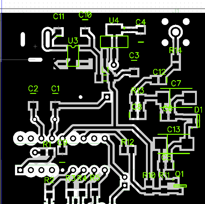
Now let's get started. Here is our schematic diagram.
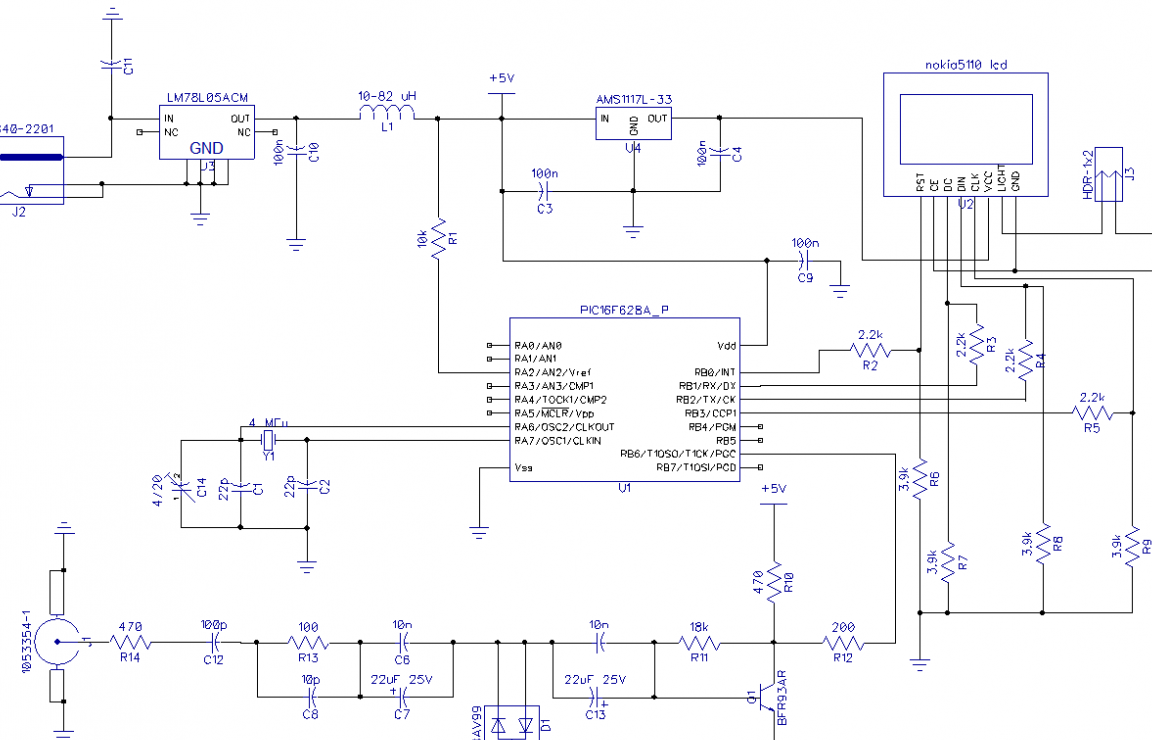
Jumper J3 we control on / off the backlight. Further it will be easier to explain on the board.
In place of jumper J3, you can bring the switch on the wires. The holes for the J2 power connector can be made with an engraver or a mini drill, making several consecutive holes. Do not confuse the polarity of the inclusion of tantalum capacitors. The BAV99 diode in series has the function of overvoltage protection. If you delve into the details, then understand the principle of operation of such protection arises from the characteristics of the current-voltage characteristic (current-voltage characteristics) of the diode.
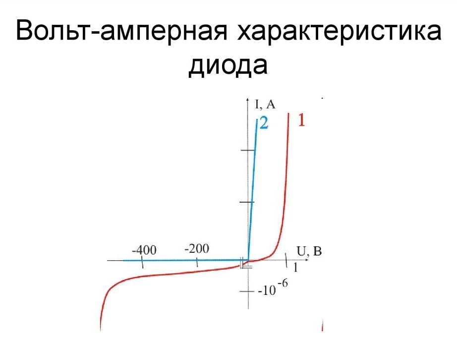
On the right side of the graph, we see that at a slight voltage the current is almost absent, but at a certain moment the current increases sharply, and a further increase in voltage does not increase the current. So, if the voltage on the diode exceeds the voltage drop, then our diode conducts current.
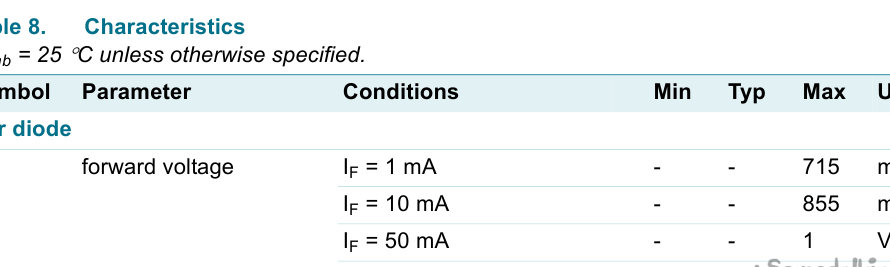
Excerpt from the documentation. Here you can see that at voltages above 1V and further, the diode starts to conduct current. In our case, it turns out that it simply shorts the input signal of large amplitude to the ground.
Resistors in the circuit of the measured signal limit the charge current of the capacitors. Indeed, in theory, when the capacitors charge and discharge, their current tends to infinity. In practice, this current is limited by the resistance of the conductors, but it is not enough.
Since our display is powered by 3.3V via a voltage regulator, voltage dividers are used to match the levels. Sometimes the screen works fine even without them, but then the current load falls on the controller pins, each of which has its own internal resistance.
The inductor (in my case, the inductance smd 0805 at 82 μH) provides additional protection against high-frequency interference in the power supply, which adds additional stability to the controller.
So sort of sorted out the main points in the controller. According to the measurement algorithm, I can not tell, because the source where I managed to find incomplete information did not have source code. And again, the site itself could not be found. So now let's move on to what I did.
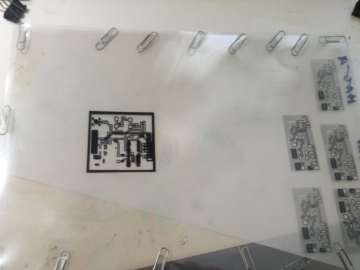
Since I don’t have a laser printer, but I have an inkjet printer, I’m making a board using film photoresist. The template consists of 4 sheets of transparent film (2 films combined films for the top layer and 2 for the bottom). Then we combine the upper and lower layers so that a board with the applied photoresist can be inserted inside.
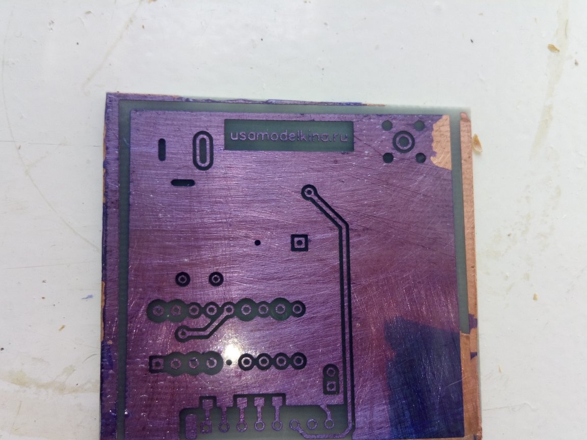
Upper layer
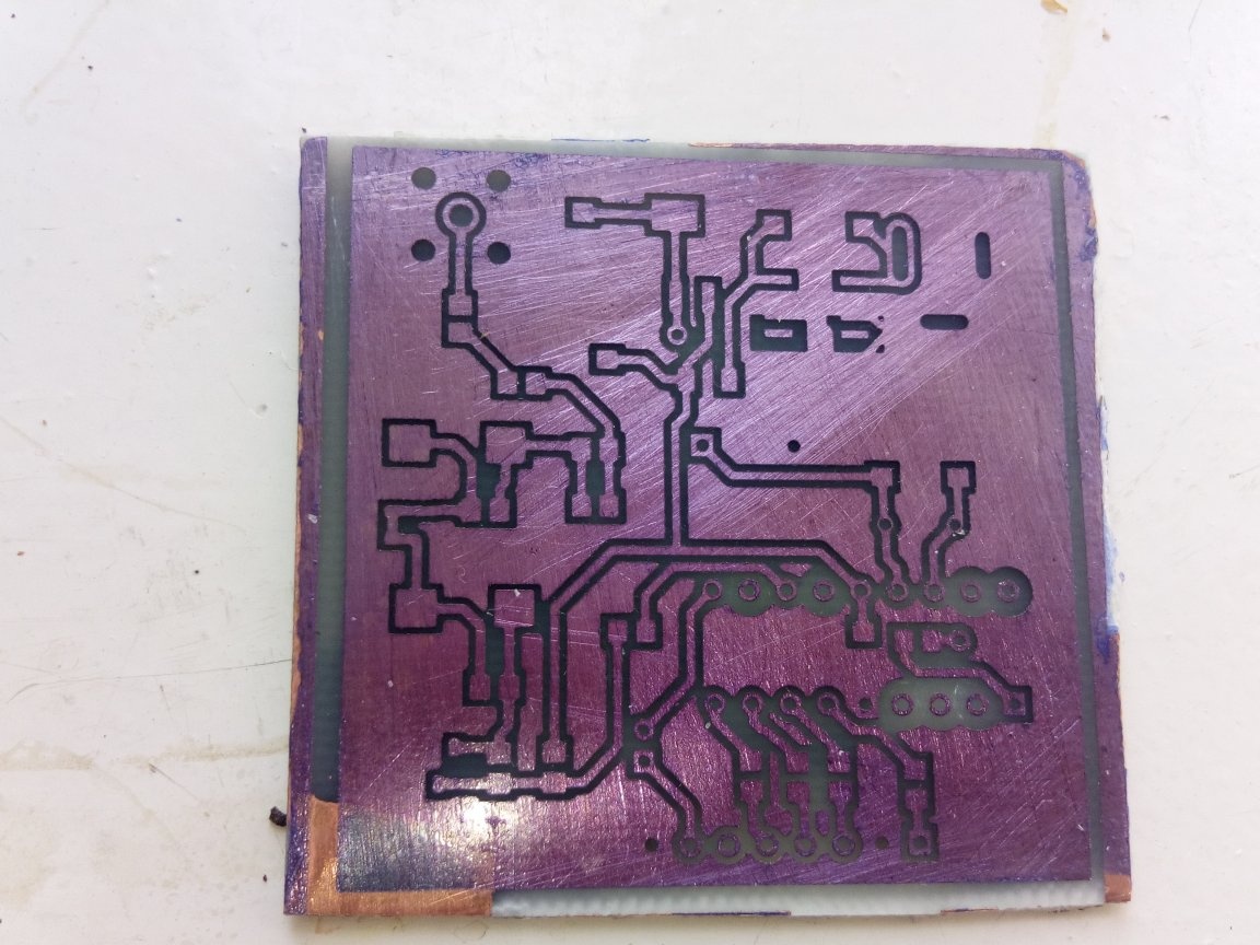
bottom layer
After etching, he made holes with his motor from a tape recorder with a collet chuck. At first he screwed it, forcing holes through it with an awl, and then he drilled through it.
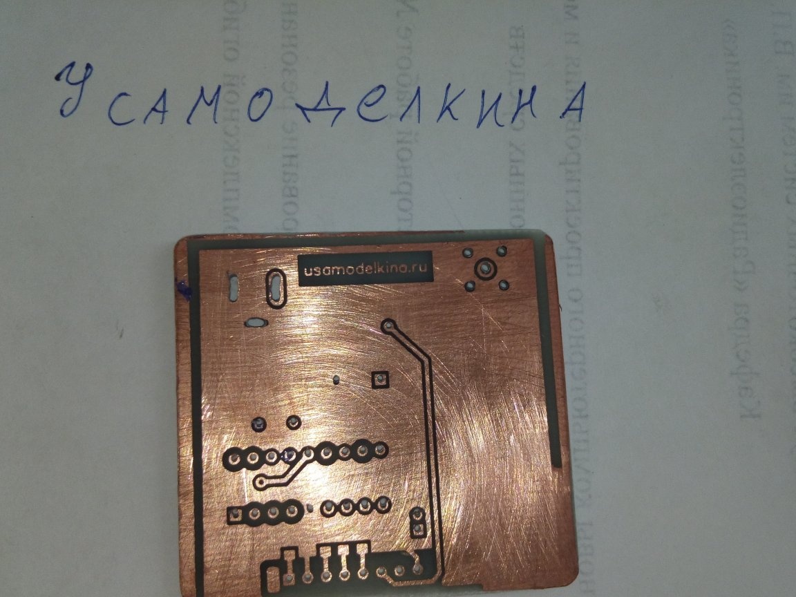
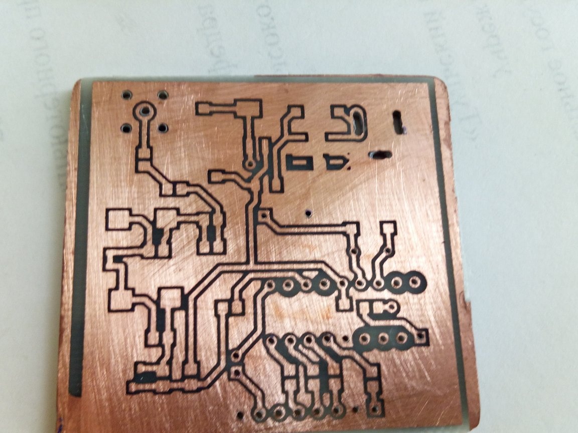
The upper photo shows not significant deviations in some holes, but this is more due to the fact that it was drilled by hand and could imperfectly hold the microdrift vertically.
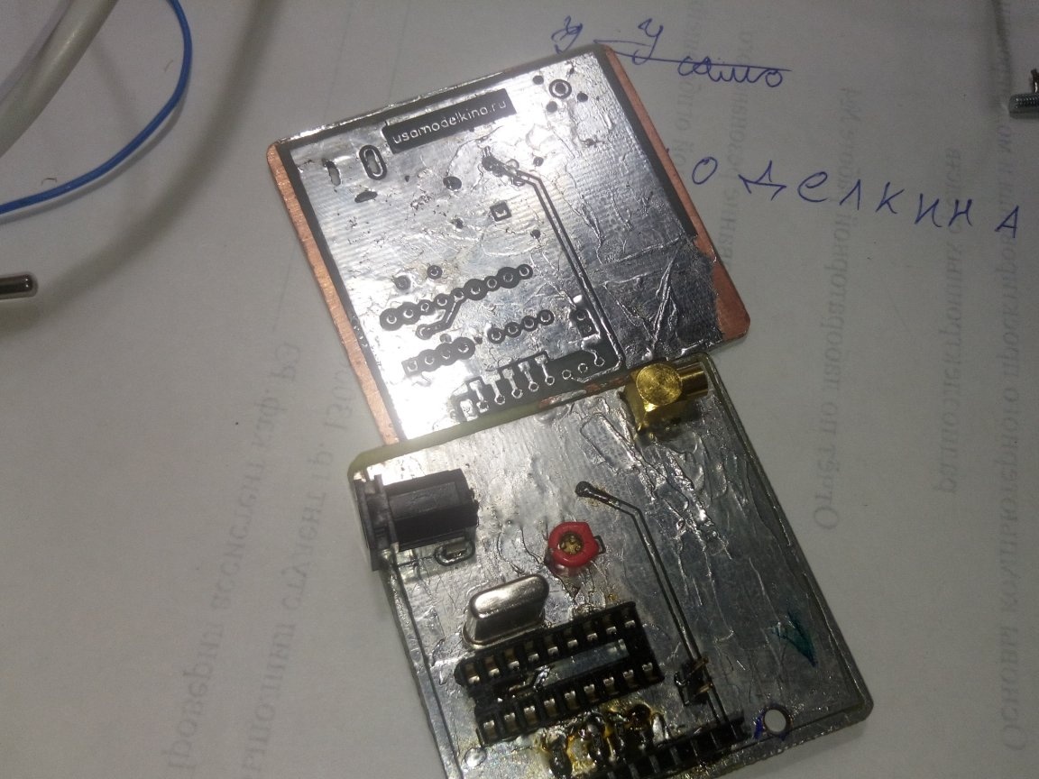
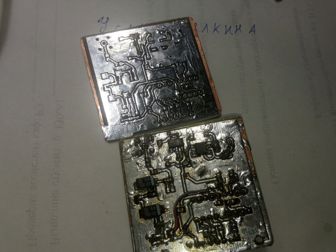
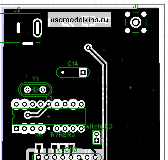
On the top of the photo of our new board after tinning, and on the bottom is my old version (it was her photo of the work that I demonstrated). The old version is slightly different from the new one (it can be seen where the red-white wire was soldered and forgot to draw the track, and the new one takes into account the wiring flaws). By the way, I would like to note how I would recommend soldering the components (in what order). First, solder the vias (there are 2 of them here), then solder the smd resistors on the top layer. Next, we solder the dip-panel under the chip so that its legs close the upper and lower holes of the board (I have 1.5 mm fiberglass and soldered to the board with some clearance for the soldering iron tip). After we install the connector for the display.
And now the most interesting: we need to make 2 holes with a diameter of 3 mm for M3x20 bolts for a more reliable fastening of our display. To do this, insert the display into the connector and with an awl through the holes we mark the places for drilling on the printed circuit board.
Well, then we solder the quartz resonator (I found an elongated one, but this is not critical here) and solder all the other components. Instead of an RF connector, you can solder a coaxial cable or, in extreme cases, just bring 2 wires.
After the board is assembled, we need to flash the PIC16F628A microcontroller. Here, I think, you can see the information on the Internet, because there are no special moments (unlike avr, where you still need to set fuses correctly).I programmed the picKit3 programmer.
Further, it would be nice to first connect the display with wires to the connector, so that you can adjust the capacitor with a screwdriver. For tuning, we apply a rectangular signal to the input and ensure that the readings are as accurate as possible, although some points depend on the signal generator itself. I used the generator from the dso quad oscilloscope, but I did not have to tighten the capacitance, because the frequency meter immediately gave accurate readings.
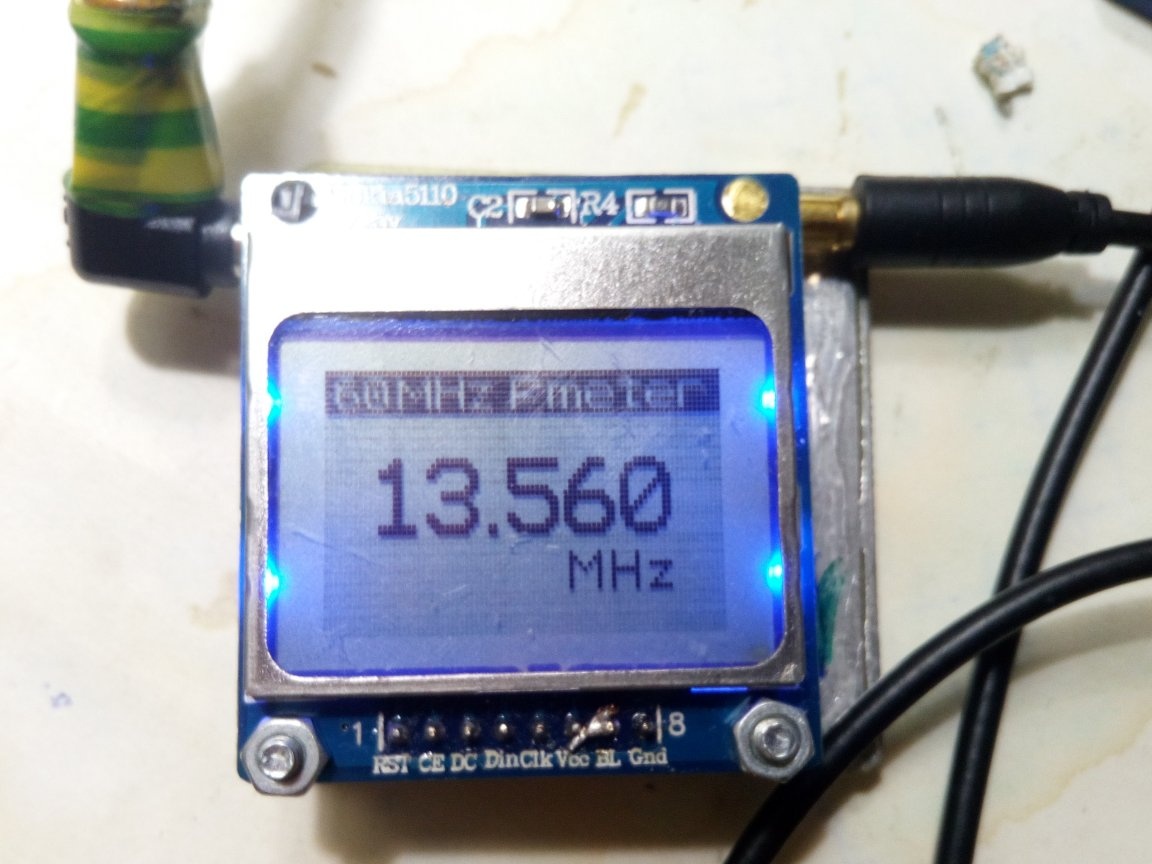
Now a few photos of the work
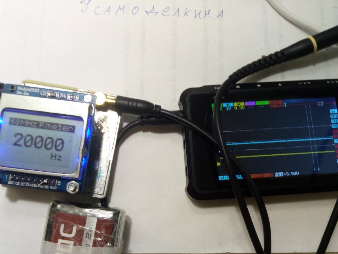
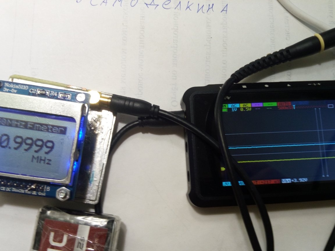
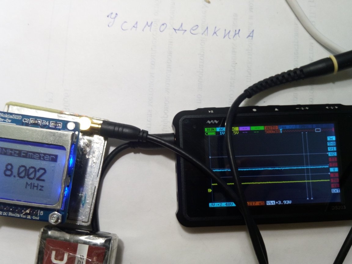
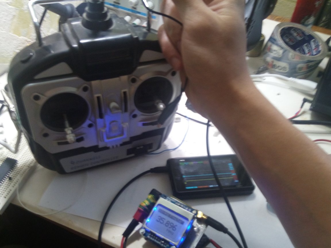
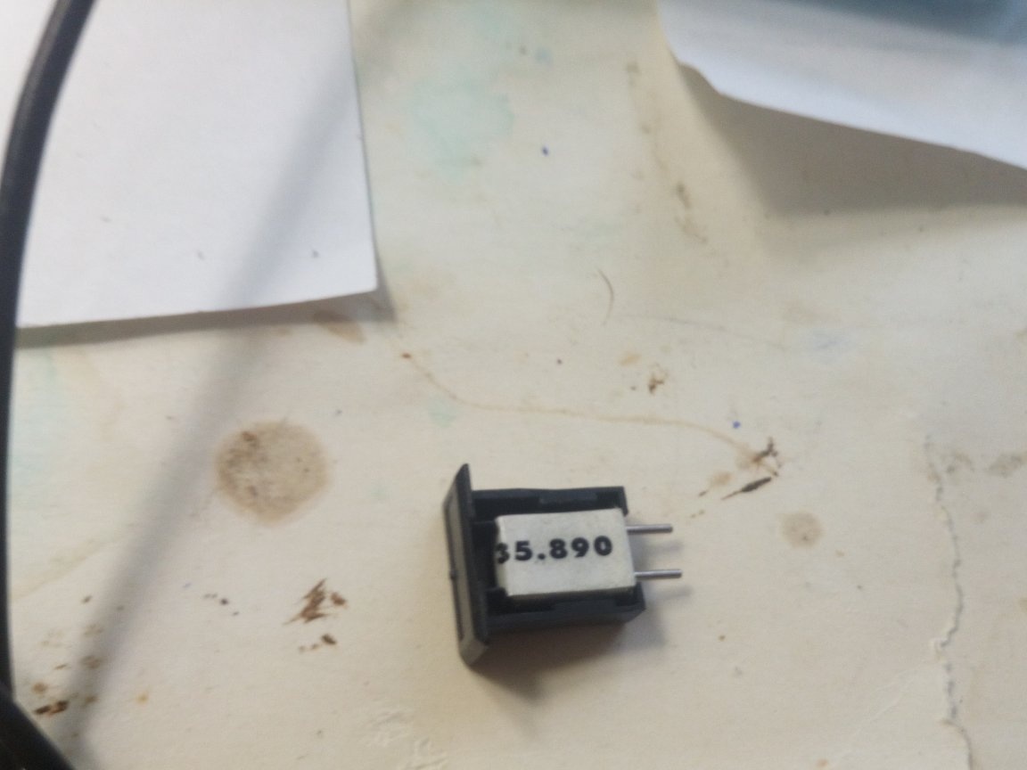
Well, that's all. It is worth noting that the frequency of the signals in the form of a saw and triangular pulses, he shows incorrectly. But sinusoidal, rectangular for sure. With it, I experimented with a capacitive three-point and a crystal oscillator.
Circuit, PCB, and firmware files are attached