
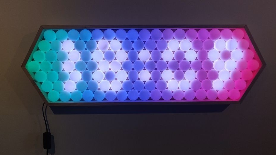
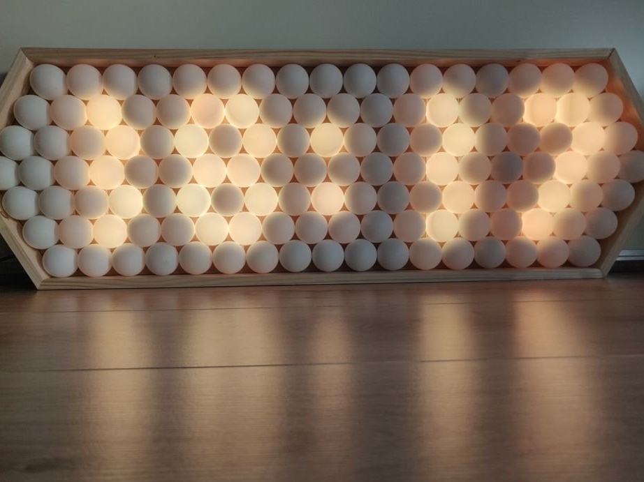
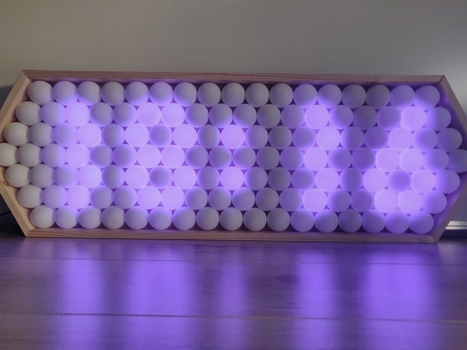
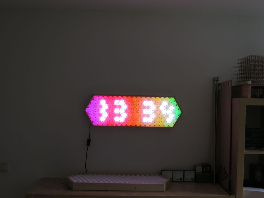
This amazing LED watch is a pretty simple project that almost anyone can do.
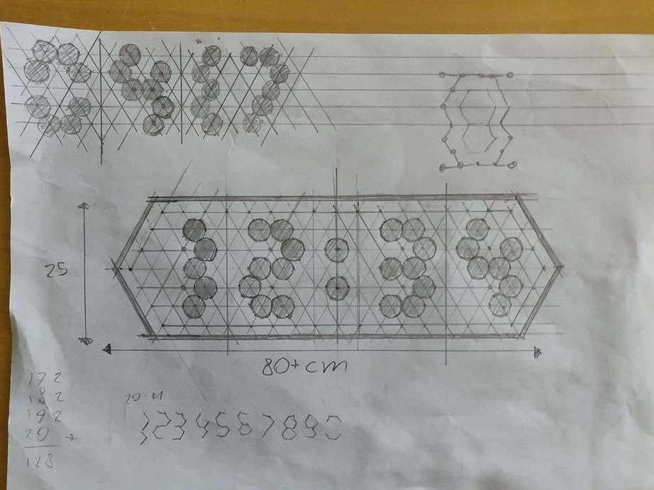
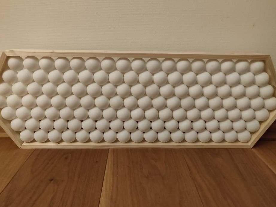
Since the ping-pong balls are not oriented in the matrix, the author had to come up with a good way to display the numbers. The design, on which he stopped, uses 12 balls for each digit, after some experiments it turned out that this allowed to get the most clear representation of the numbers.
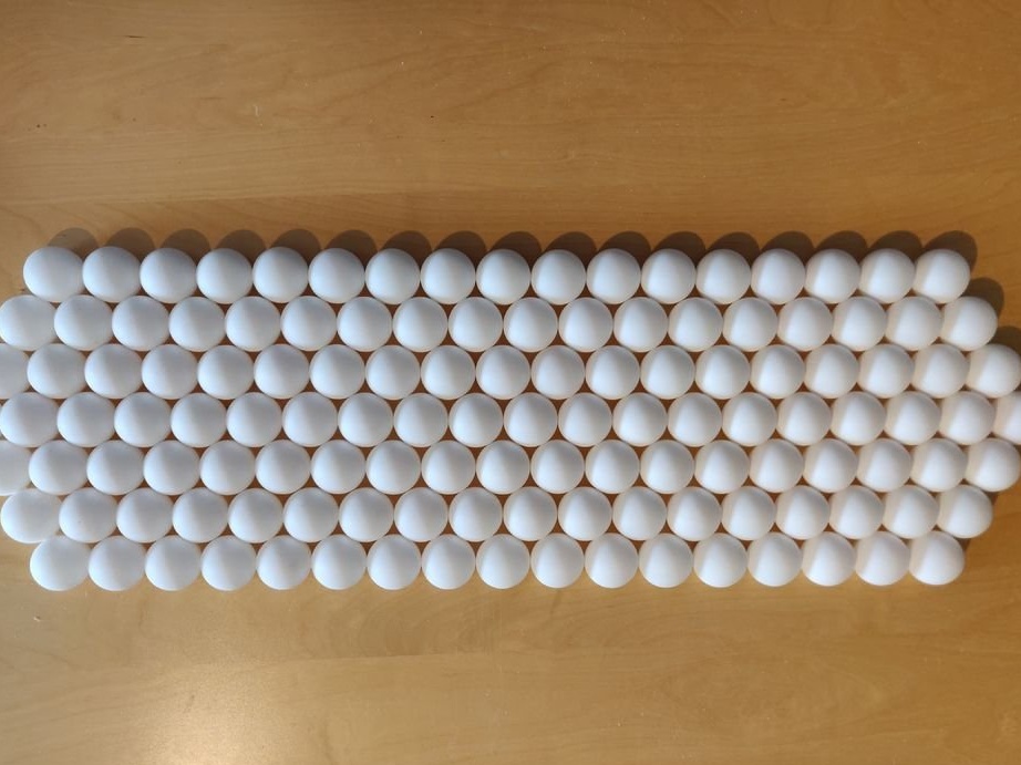
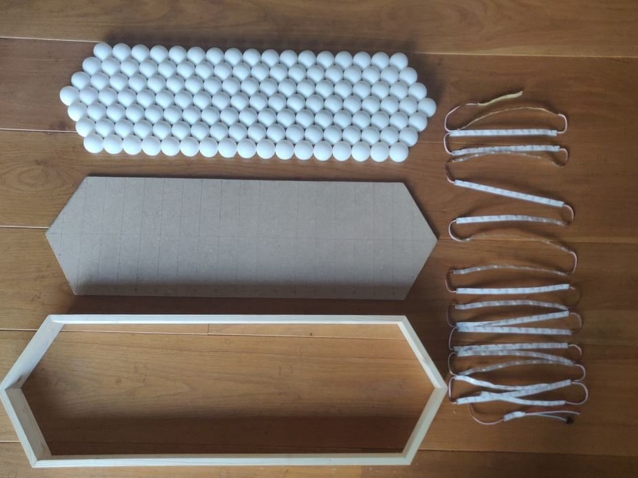
In total, 128 balls were used for the entire display.
Step 1: Materials / Tools:
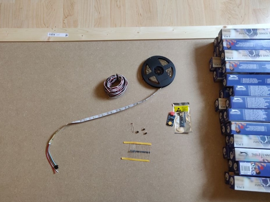
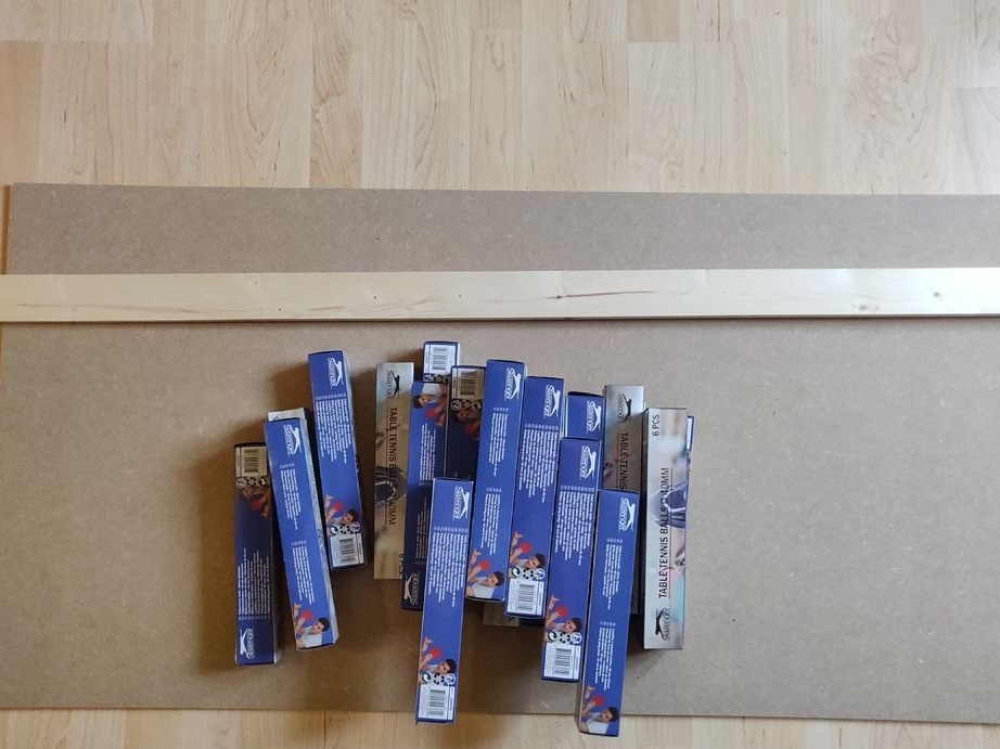
- MDF 80 * 30 cm (you can replace MDF with a laminate or fiberboard)
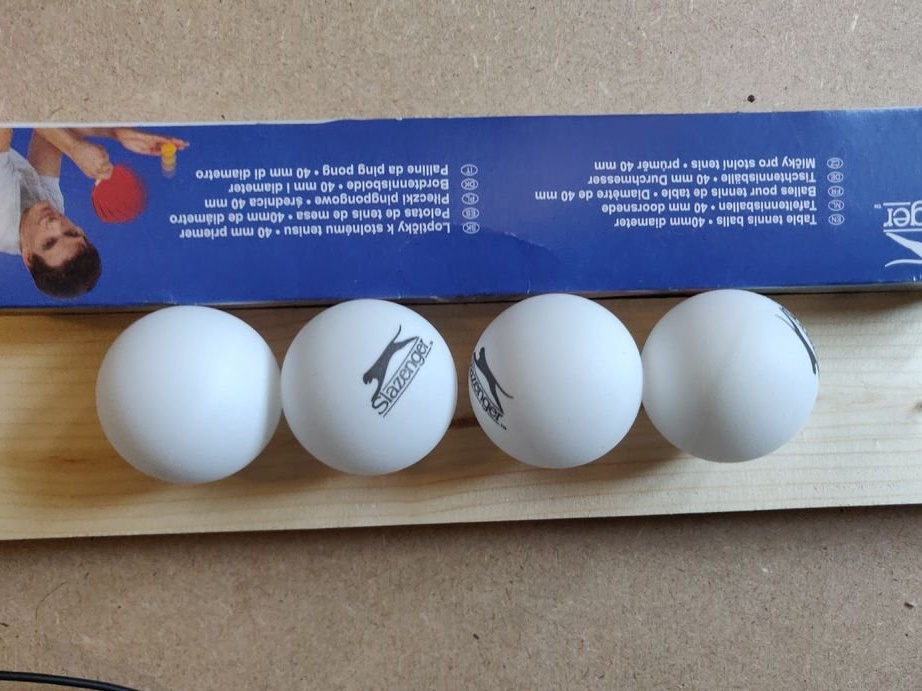
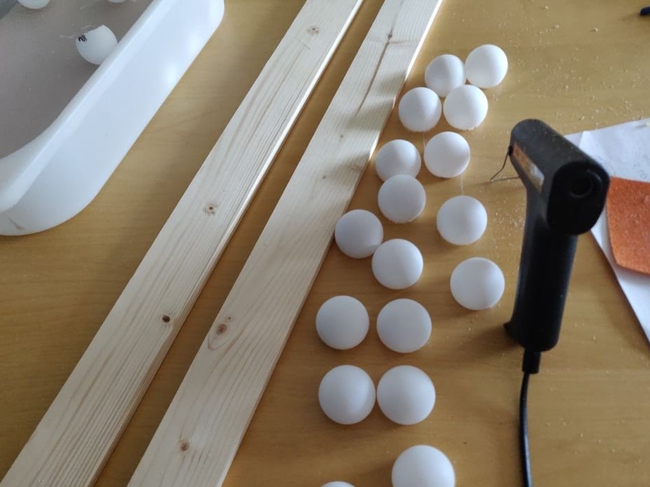
- 128 ping-pong balls (white, preferably milky white)
- Small furniture nails
- Old USB cable (for power Arduino nano)
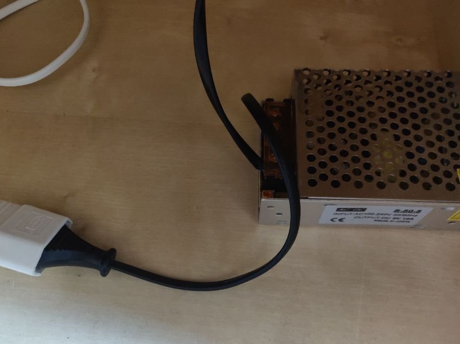
- Cable with plug from unnecessary equipment
- Power Supply 5V 10A
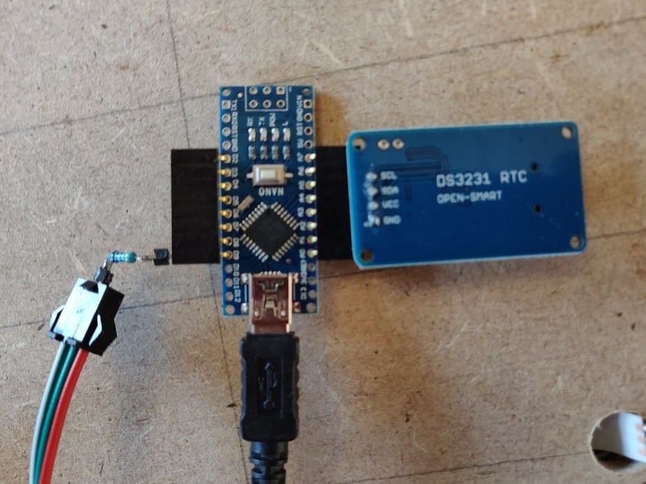
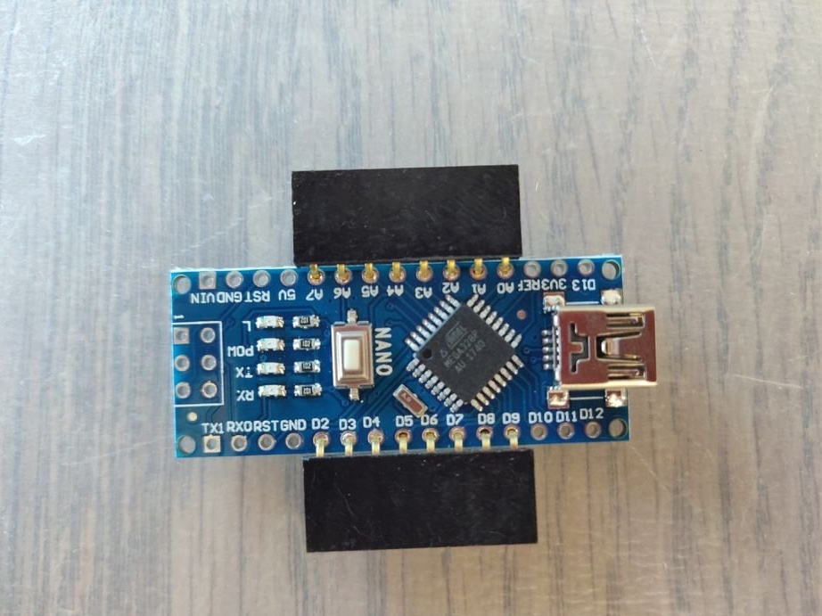
- Arduino nano
- LED strip ws2812b (5m, 30 leds / meter, IP30 class)
- DS3231 Real Time Clock Module
- 3-core wire (2+ meters)
Instruments:
- Miter saw (or a sufficient level of skill to cut exactly at 30 degrees without it)
- Hacksaw
- Soldering iron
- Drill or screwdriver
- 32 mm crown
- Wood glue
- Hot glue gun (with glue)
- Flashlight
- Sandpaper
Foreword
The choice of balls is an important part. Ping-pong balls typically have a seam connecting the two hemispheres together. This in itself is not a problem, since with the correct arrangement of the balls, in the end, this seam will not be visible on the display. However, often on the balls there is a logo of the manufacturer's company, which will be cut out in the process. You need to look so that the logo does not lie on the seam, but is on one side of the hemisphere. Colored balls are also not suitable. It is advisable to use seamless ping-pong balls without printing, but not all of these can be bought.
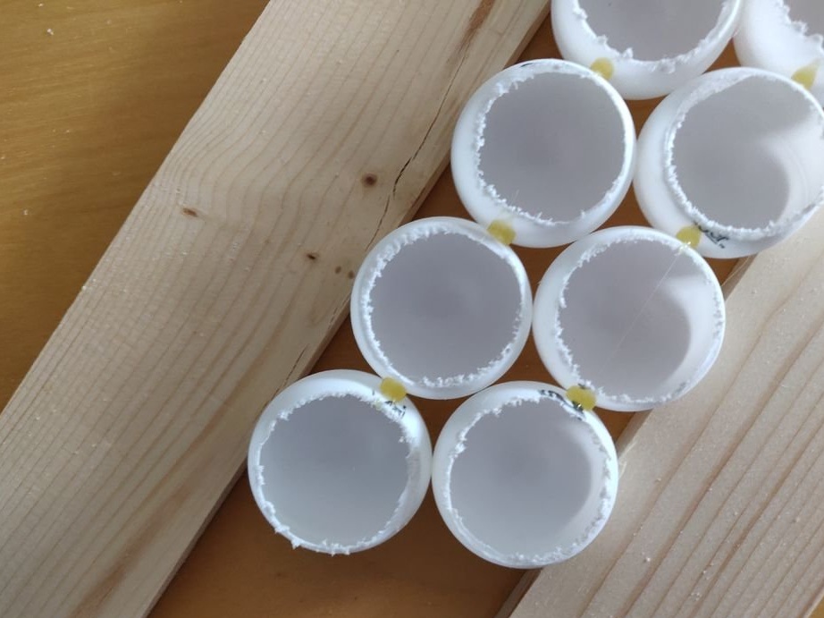
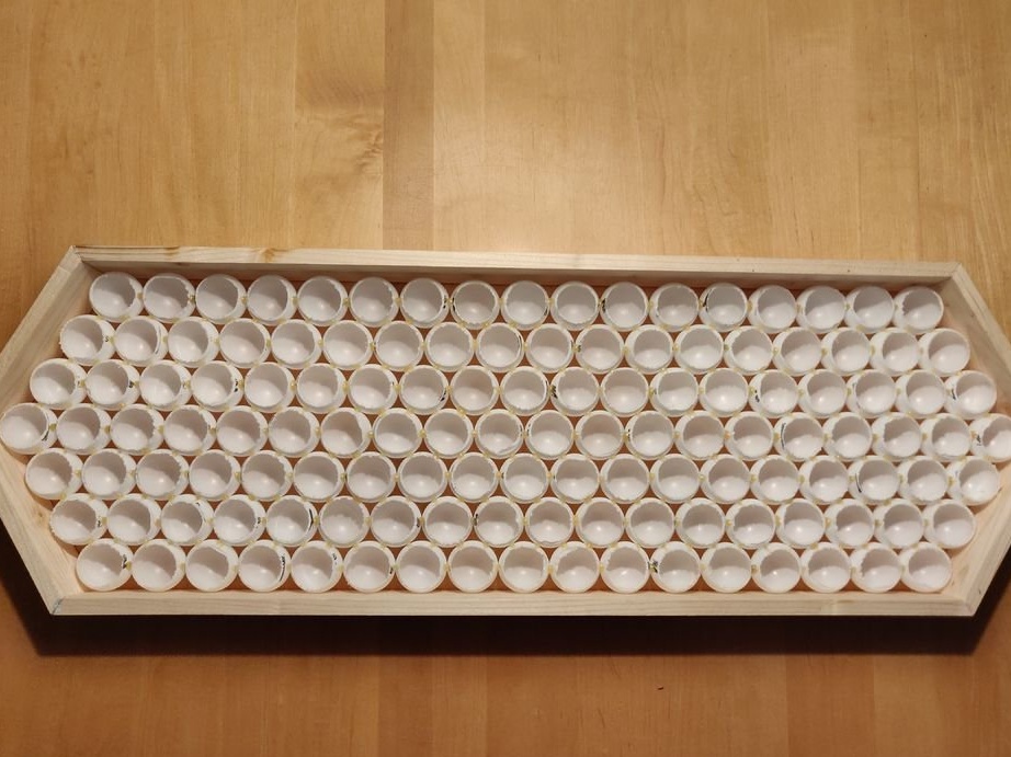
Step 2: Cut Balls
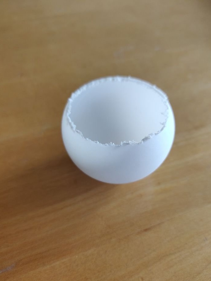
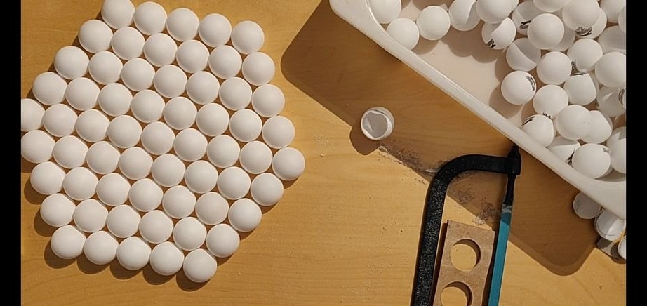
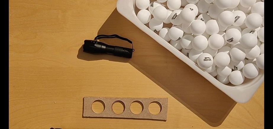
Each ball will have its own LED. In order to achieve the best light transmission and good dispersion, the balls need to be cut off on the one hand, making it a kind of shade (example: like on street lamps). These holes should be large enough (approximately 30 mm), since it will not be possible to arrange the LEDs always strictly in the center.
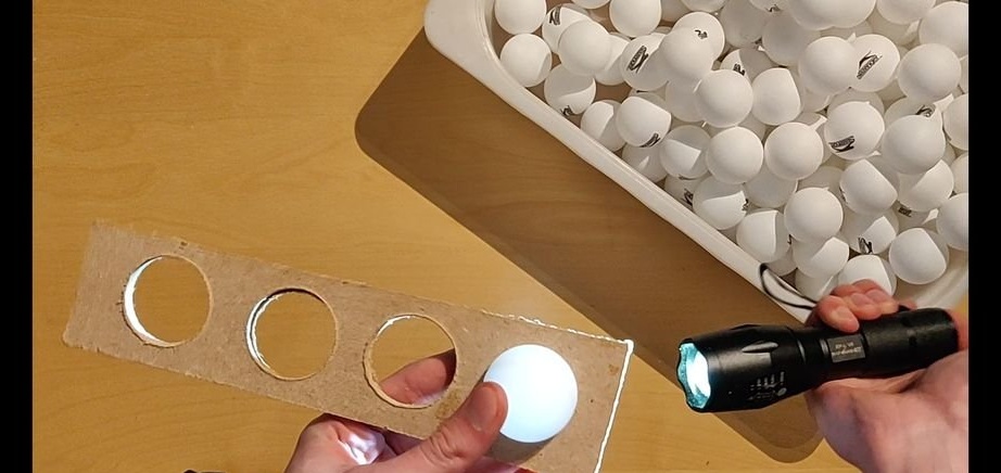
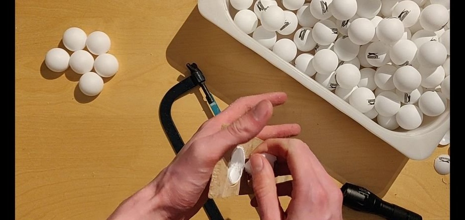
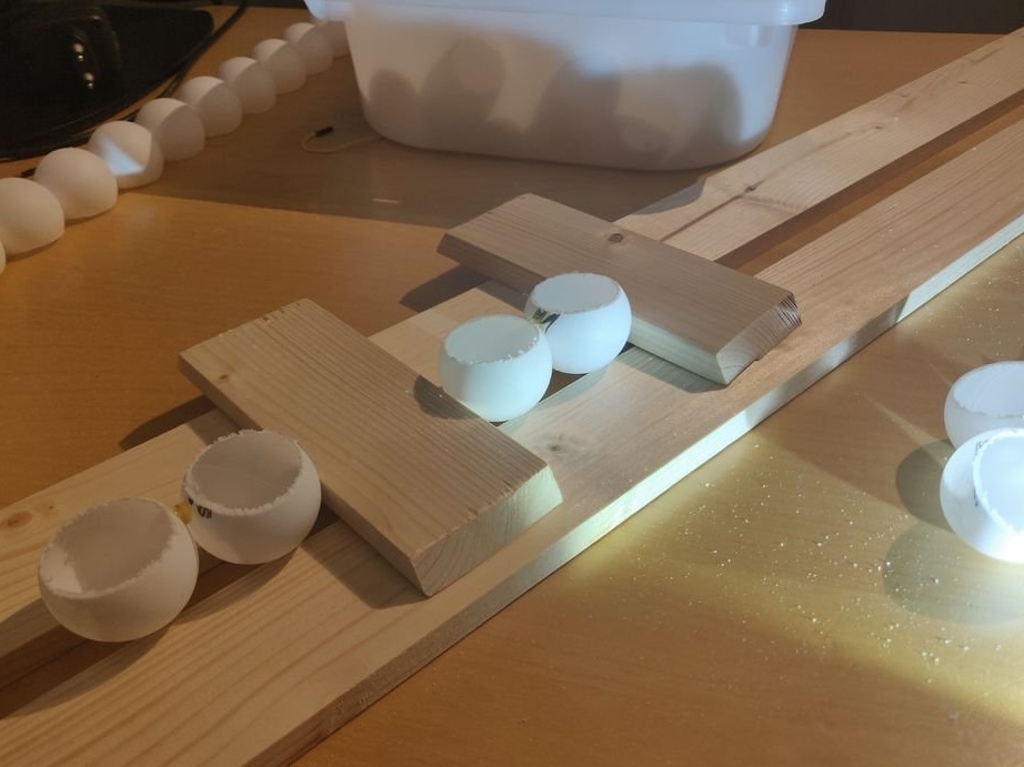
To do this, a 32 mm diameter hole is drilled in a piece of dense material, a ball is pressed against this hole and, on the other hand, the protruding part is cut with a hacksaw. The logo should get onto the cut-off part, if there is one, and in order to make sure that the seam does not fall on the “front” side of the lampshade - the ball is highlighted with a flashlight.This complicates the task, which is why it is desirable to use seamless balls.
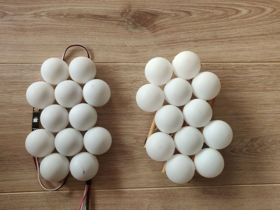
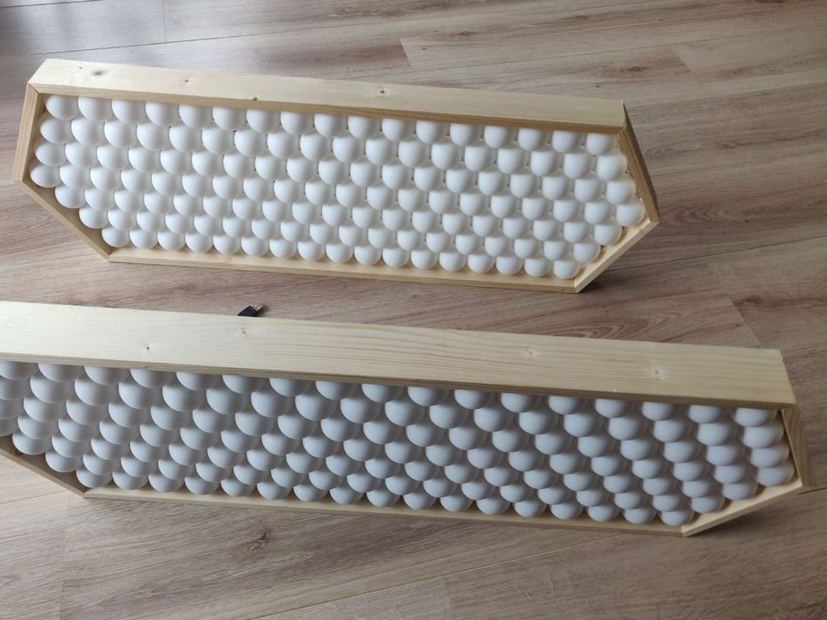
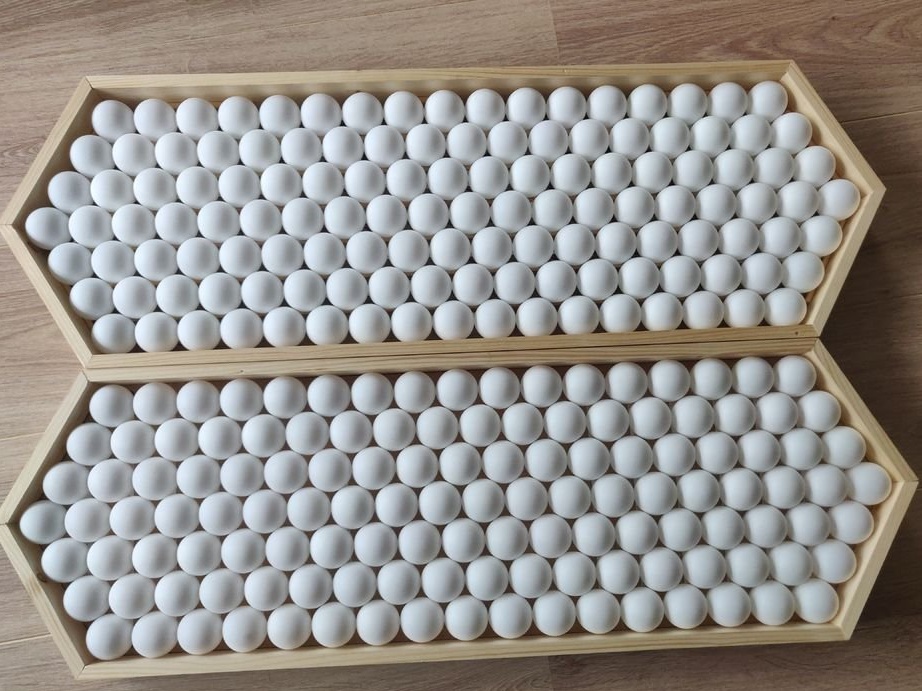
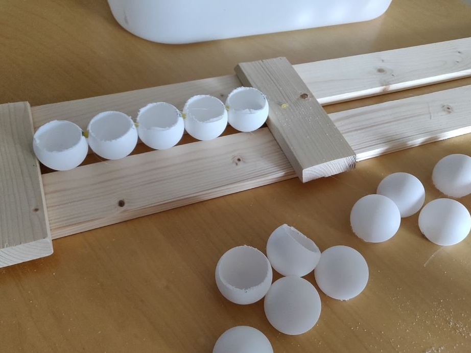
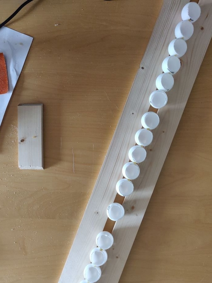
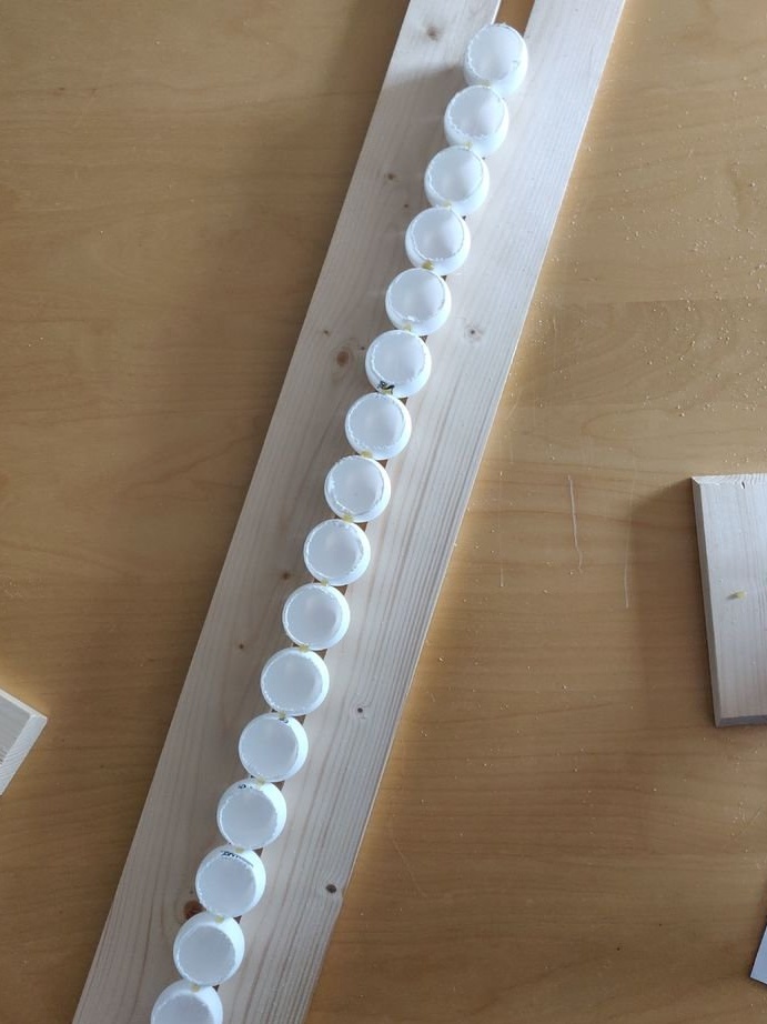
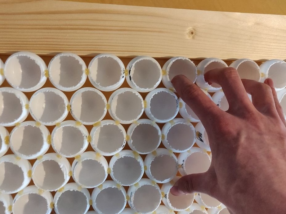
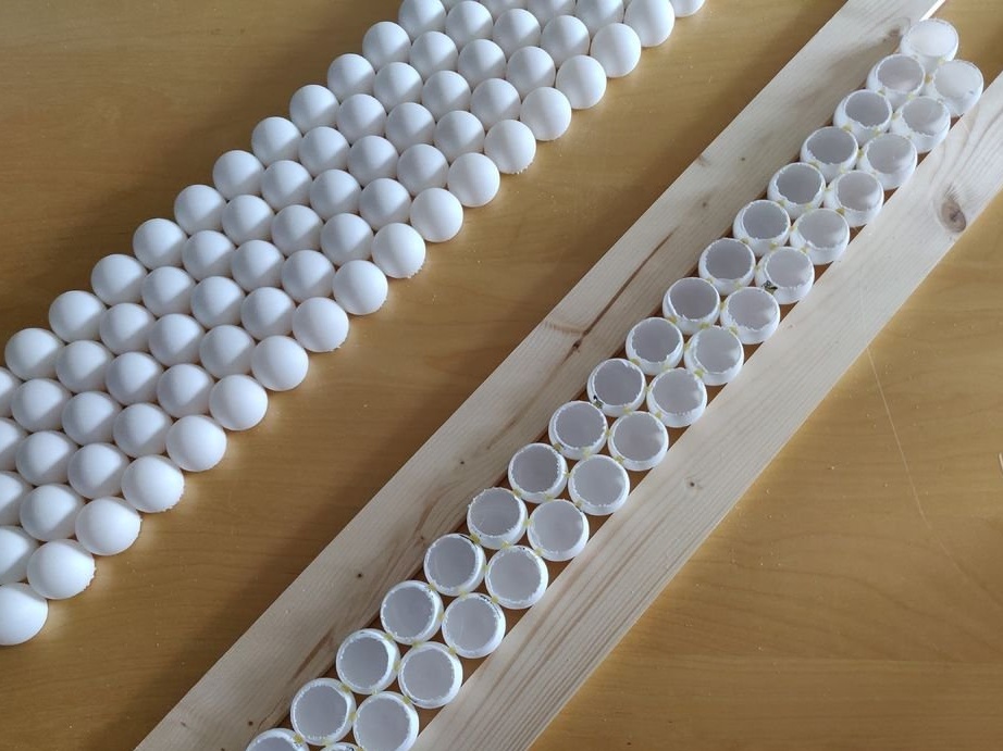
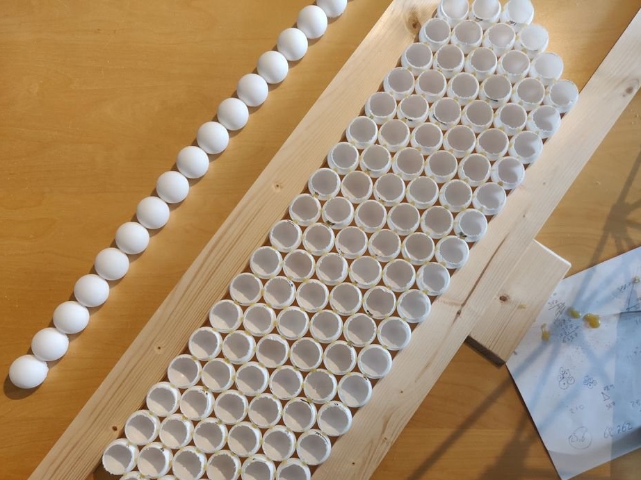
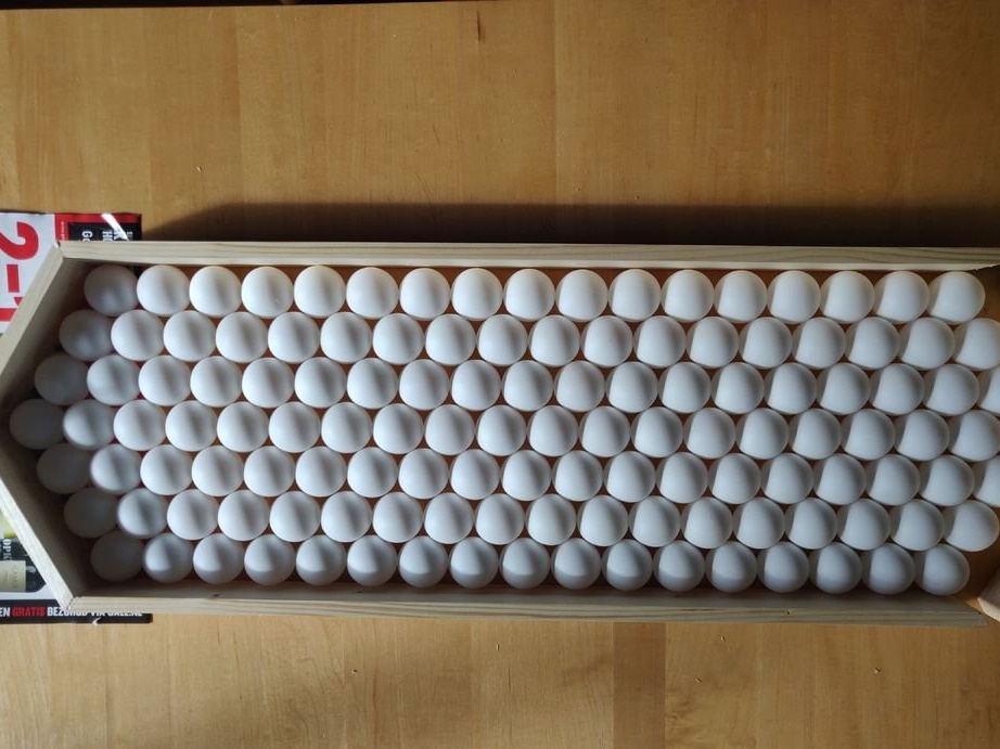
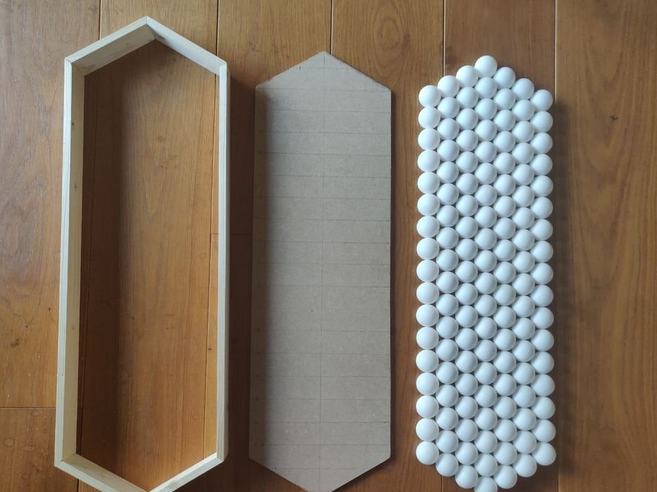
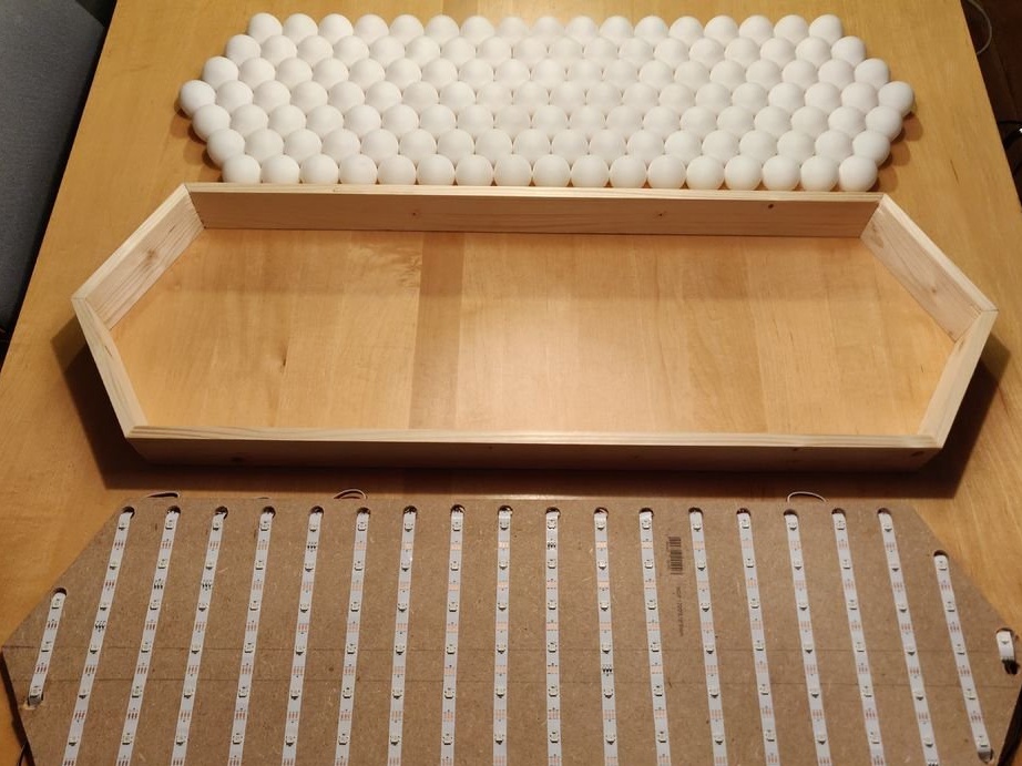
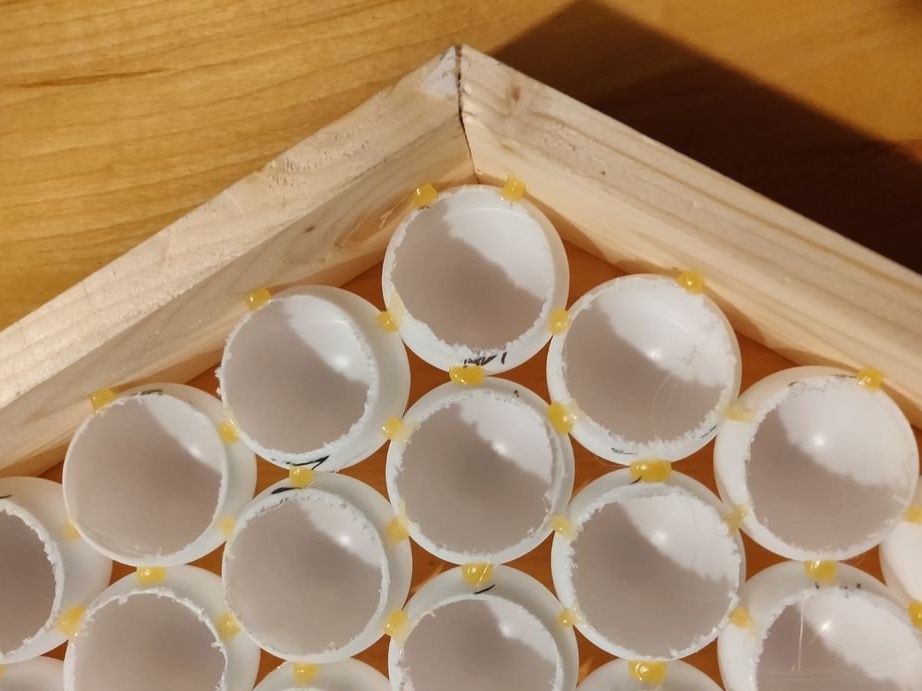
Step 3: Gluing the balls in rows
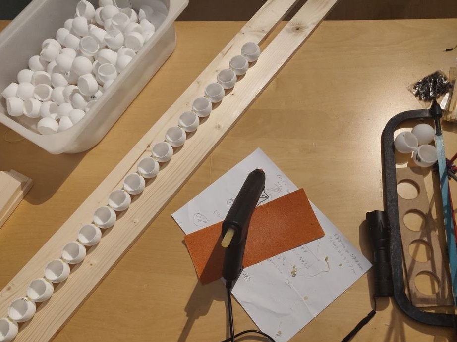
Having made holes in all the ping-pong balls, they must be glued together in rows (2 rows of 17, 18 and 19 balls, and one row of 20). These rows should be as straight as possible, and there should be no gap between the balls. It is convenient to do this by placing the balls between the two rails, placing them with the holes up. After that, the balls are glued together with a small amount of hot glue on each side. There should be a little glue, otherwise it will be visible in the end.
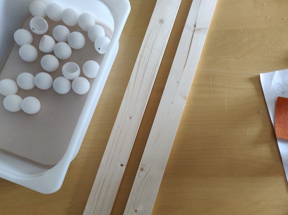
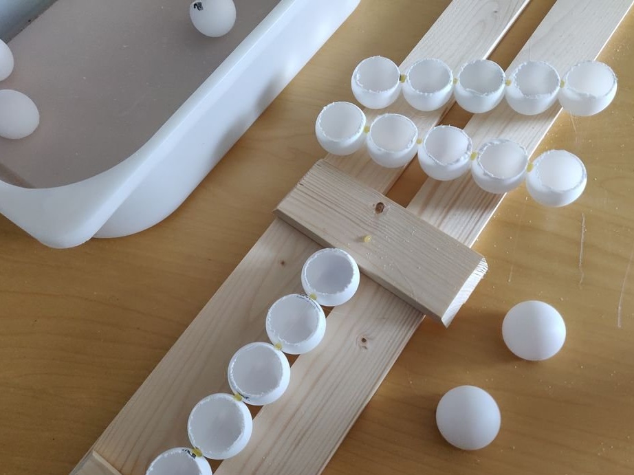
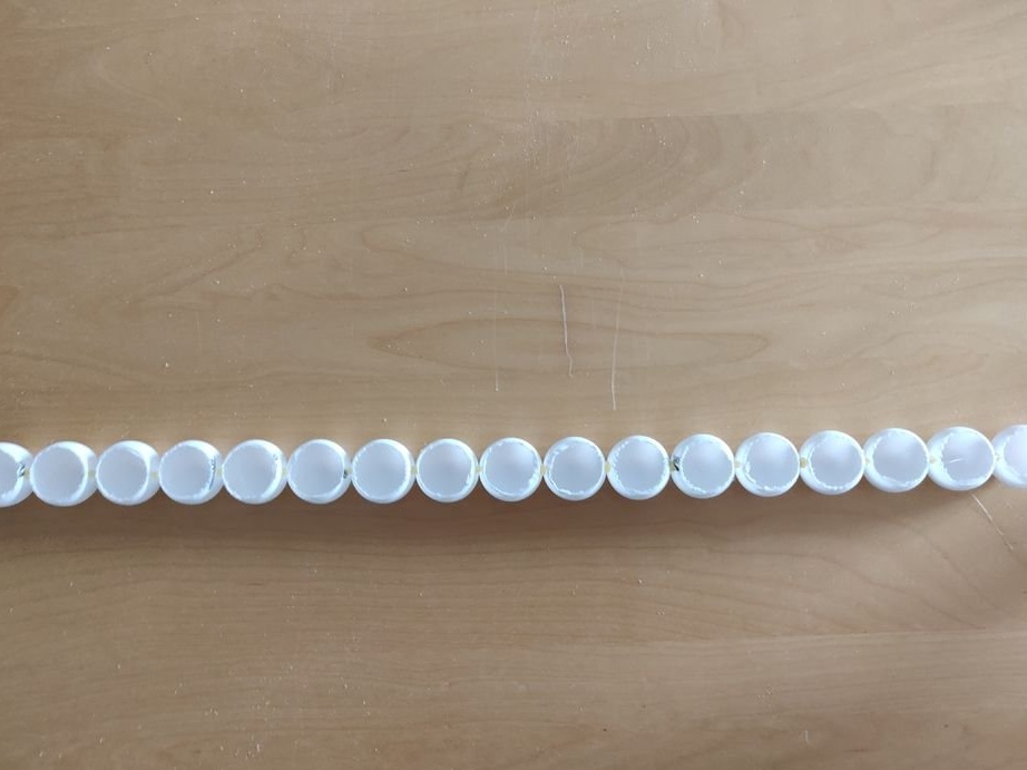
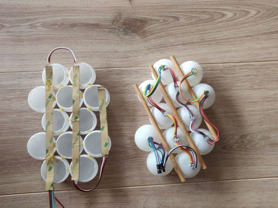
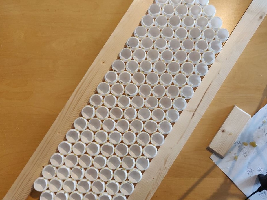
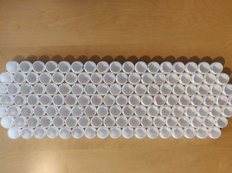
Step 4: Bonding Rows
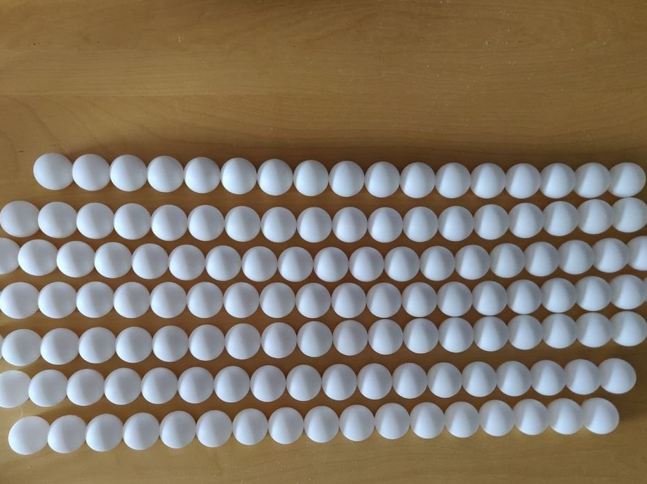
This is done again with the help of rails, but now between them are already rows. Again, you need to make sure that there is little glue. Applying glue for every 4 joints, the rows are pressed against each other, so that in the end there would be no gaps.
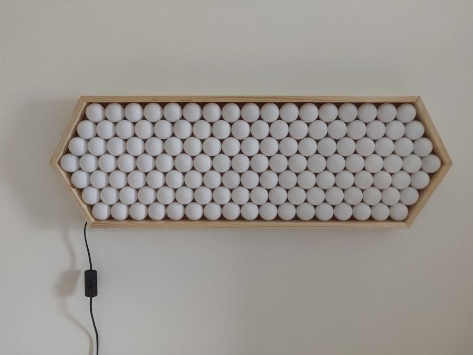
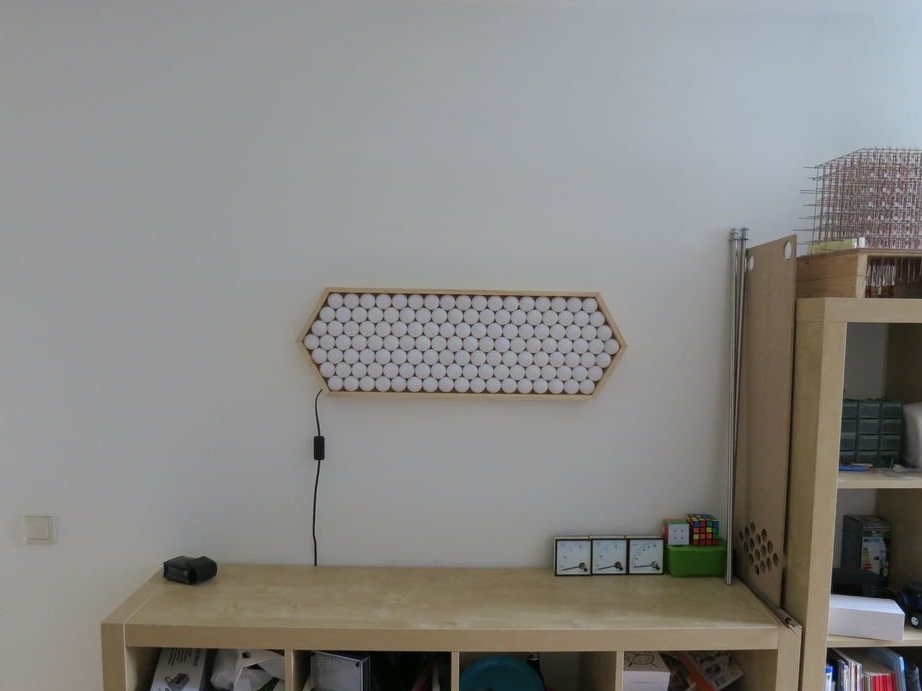
Step 5: Frame
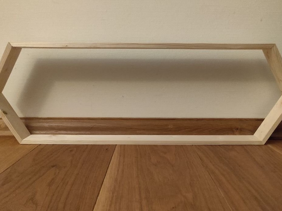
The frame is an elongated bee honeycomb, and is assembled from 6 segments. According to the norms, the ping-pong ball should have a diameter of 40 mm, however, manufacturers do not always strictly adhere to these standards, therefore, it is necessary to consider the size of the frame based on those balls that you managed to get. It’s also unlikely that gluing balls is ideal, so the size of the frame is determined empirically.
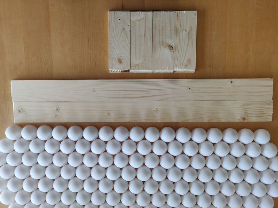
After the faces of the frame are made, they are drawn together, rows are inserted into it to make sure that everything converges, and, if necessary, is being finalized.
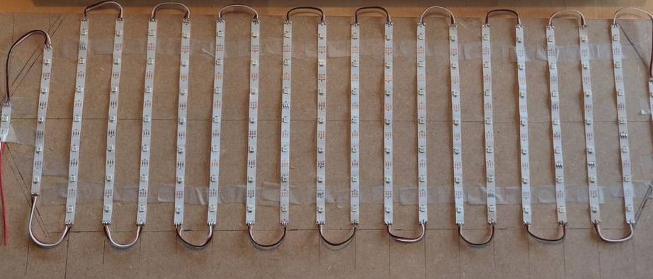
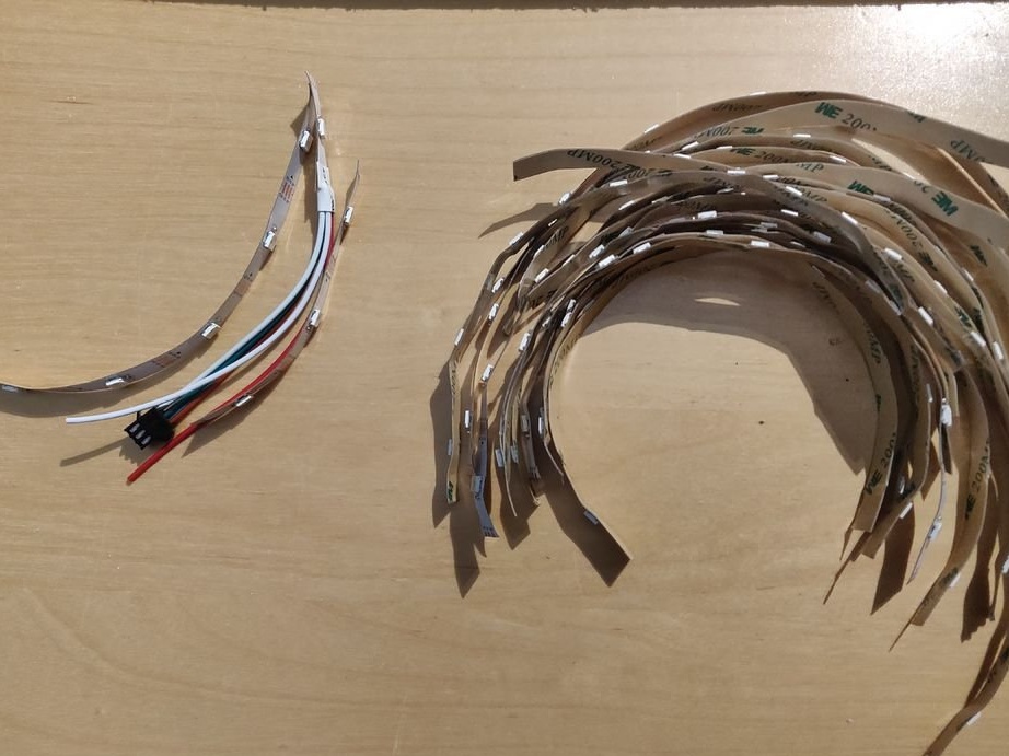
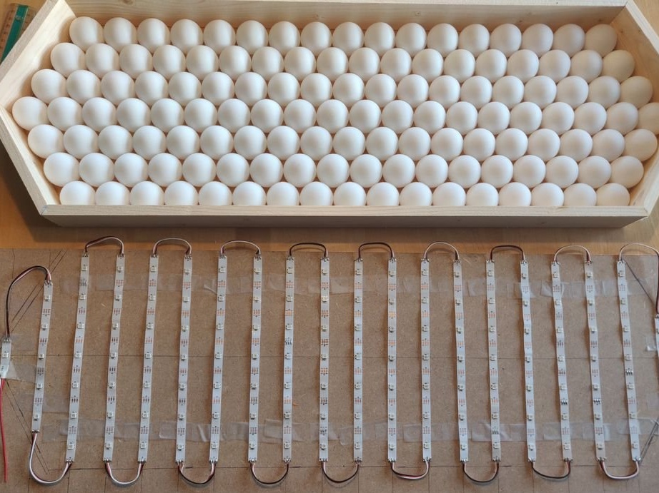
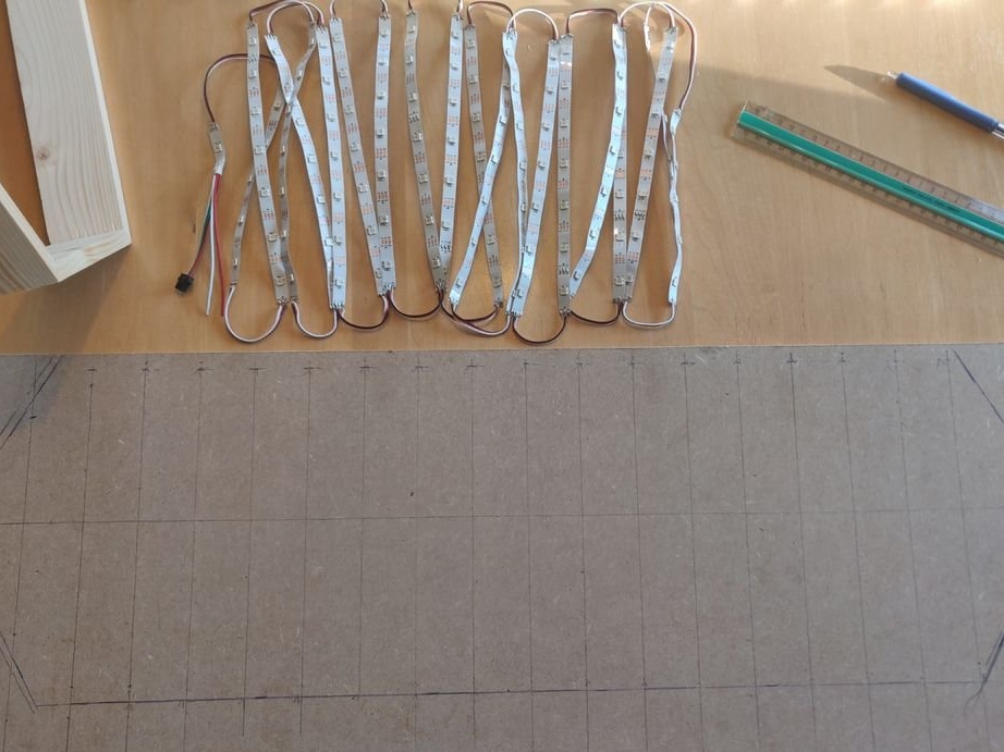
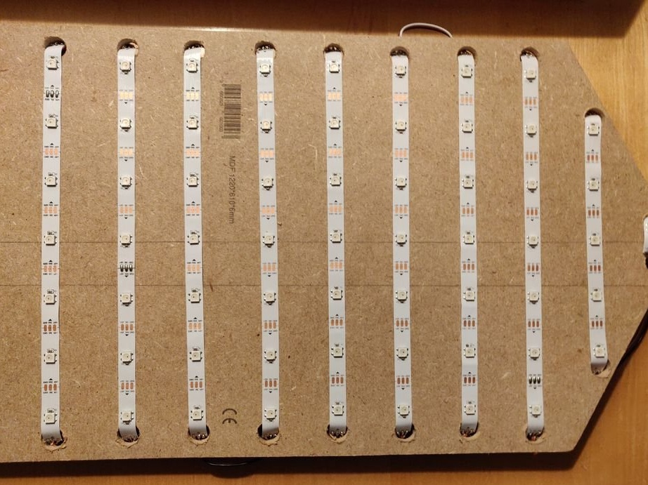
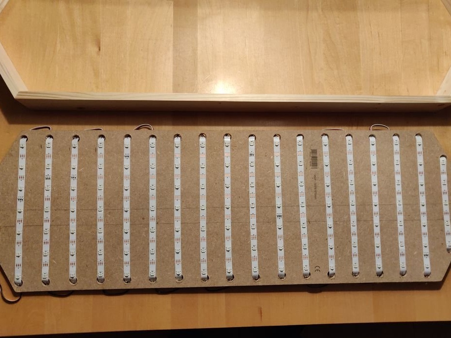
Step 6: Soldering the LED Strip
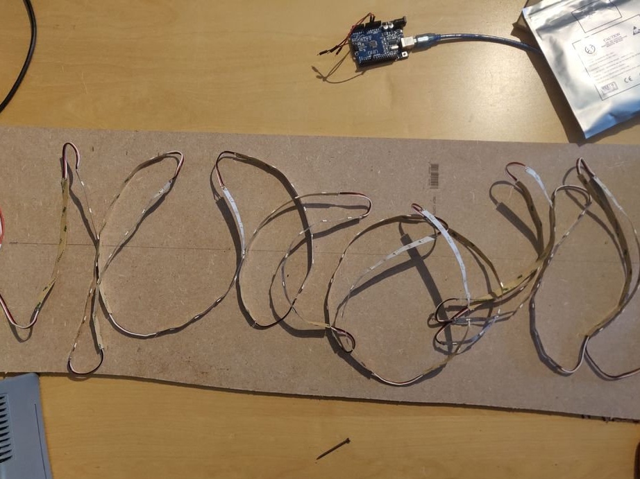
The LED strip must be cut into segments (one part of 1 LED, one of three LEDs, one of 5 LEDs and 17 of 7 LEDs). The segments are connected by wire according to the picture (1 LED, then 5, then all the segments are 17, and at the end there are 3 LEDs).
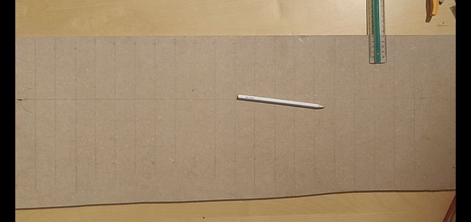
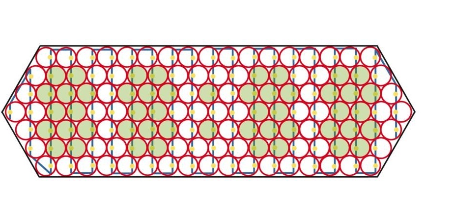
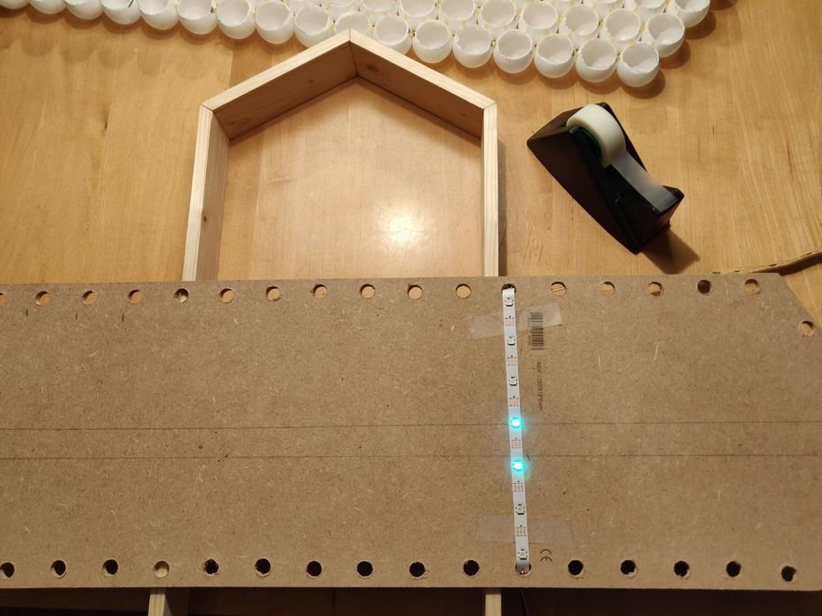
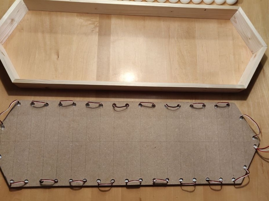
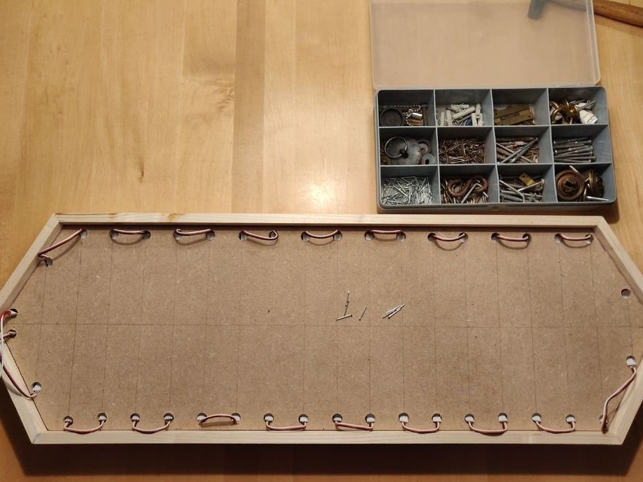
Step 7: back wall
From the MDF or fiberboard along the inner perimeter of the assembled frame, the back wall is cut out onto which the LED strip will be glued. The location of the LEDs on the tape and their correspondence with the balls can be seen in the schematic image below.
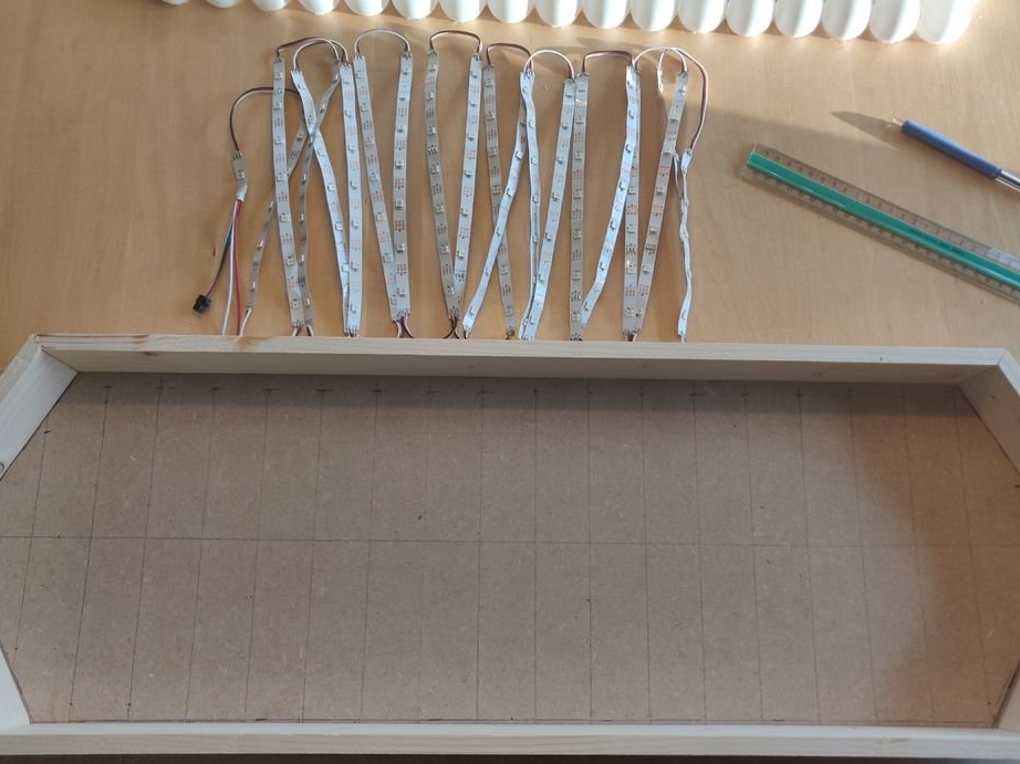
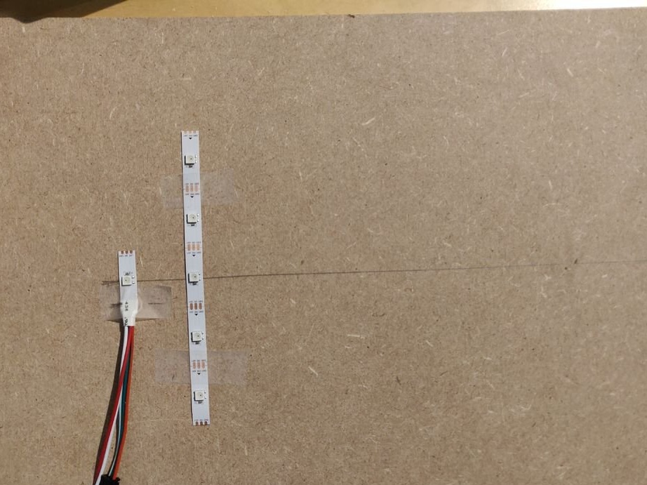
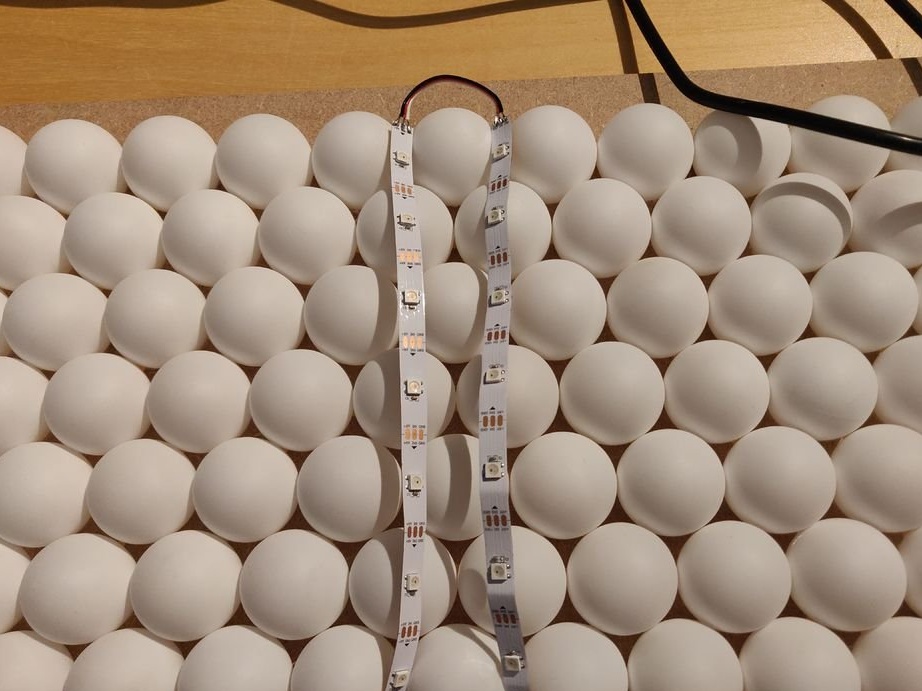
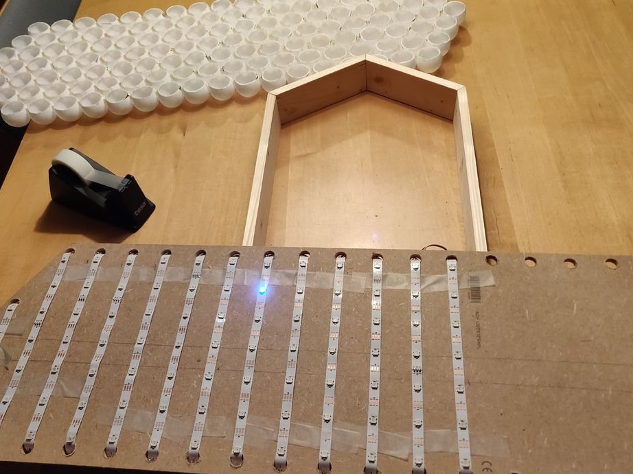
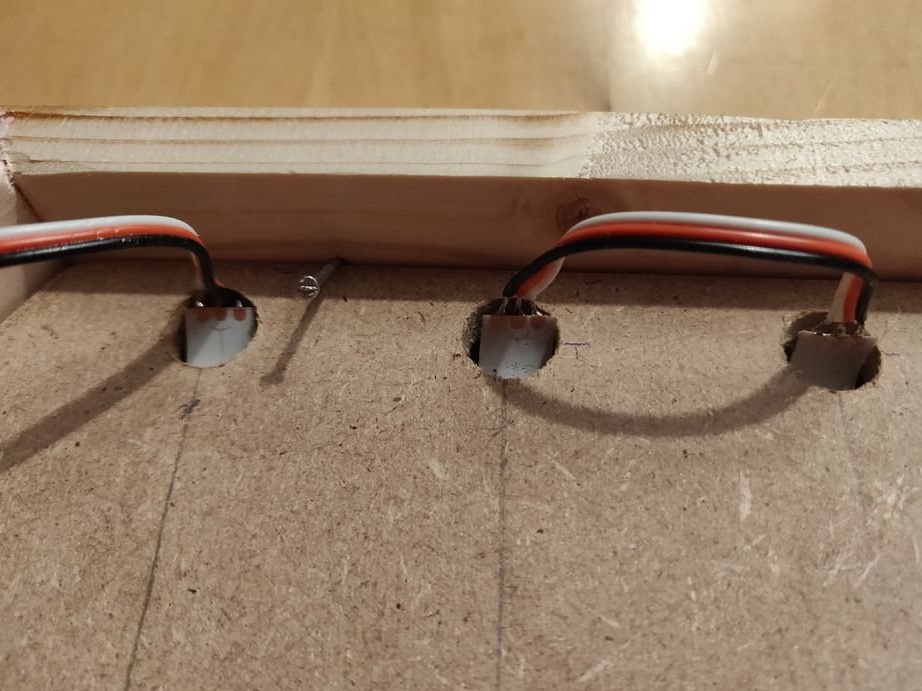
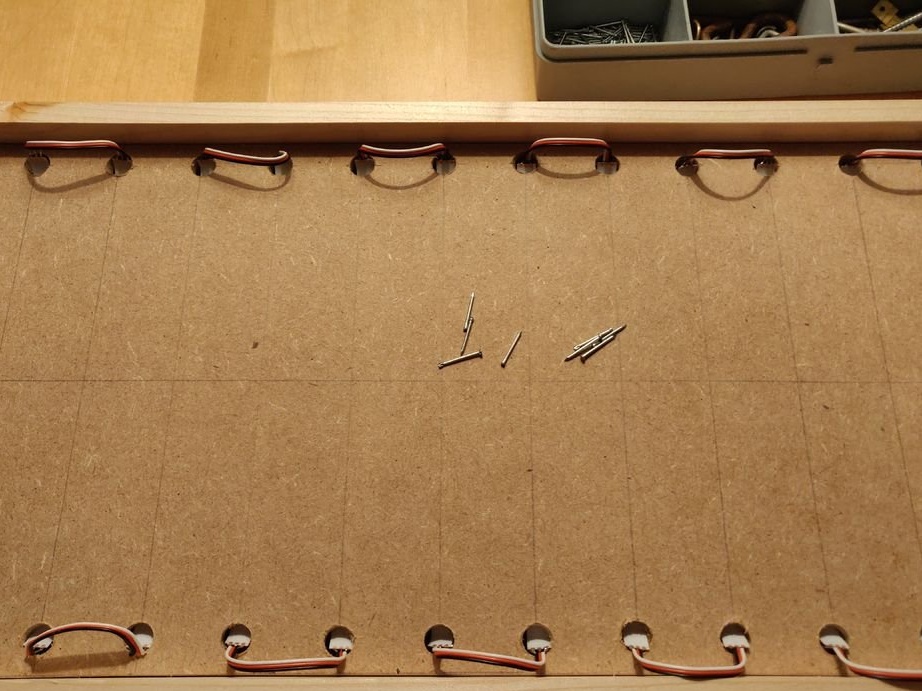
Step 8: Install LED Strip
The wires connecting the segments of the tape interfere with the normal installation of the panel of balls, so they retract. To do this, holes are drilled in the back cover slightly more than the width of the tape, and a tape is inserted into them. After making sure that each LED hits its own ball, you can remove the substrate of the adhesive layer of tapes and stick them to the base.
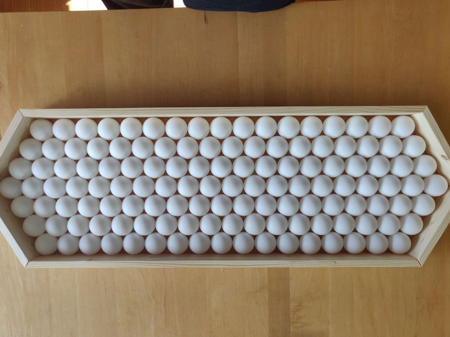
Step 9: Glue the balls to the frame
The panel is laid face down, and at each point of contact it is fixed with a small drop of hot-melt adhesive.
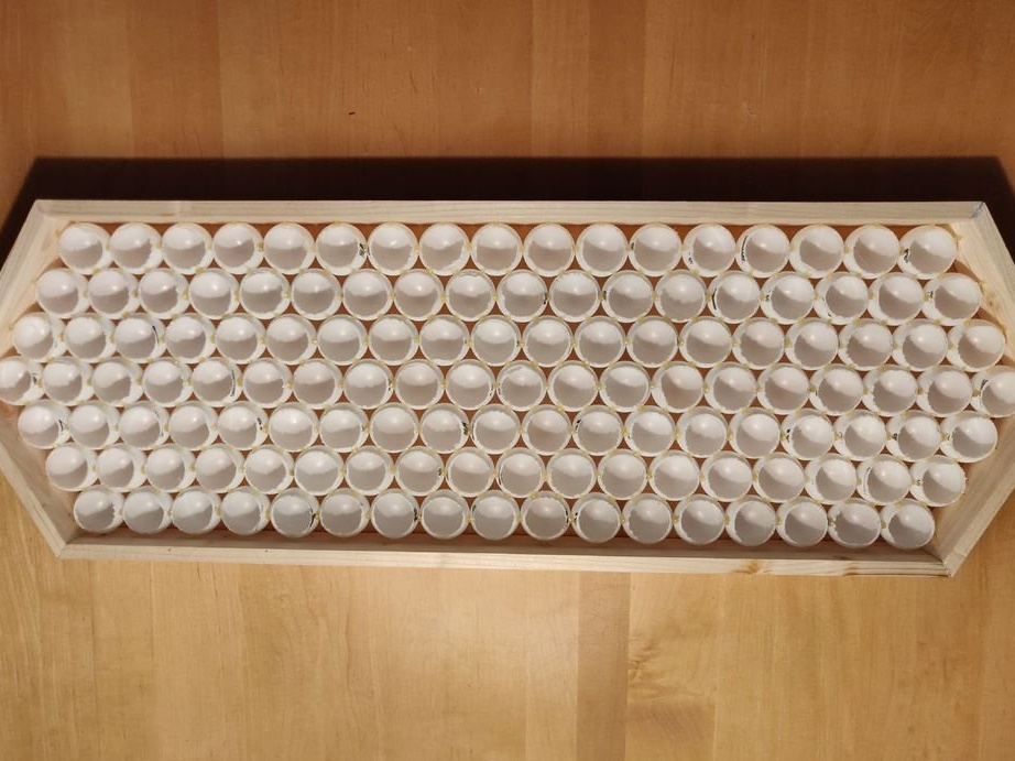
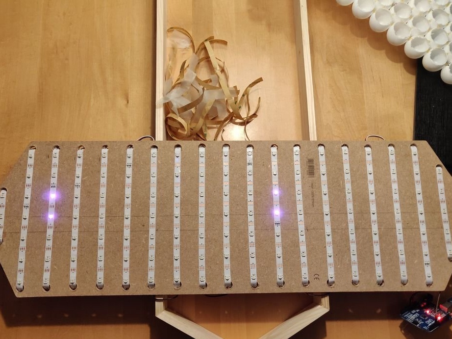
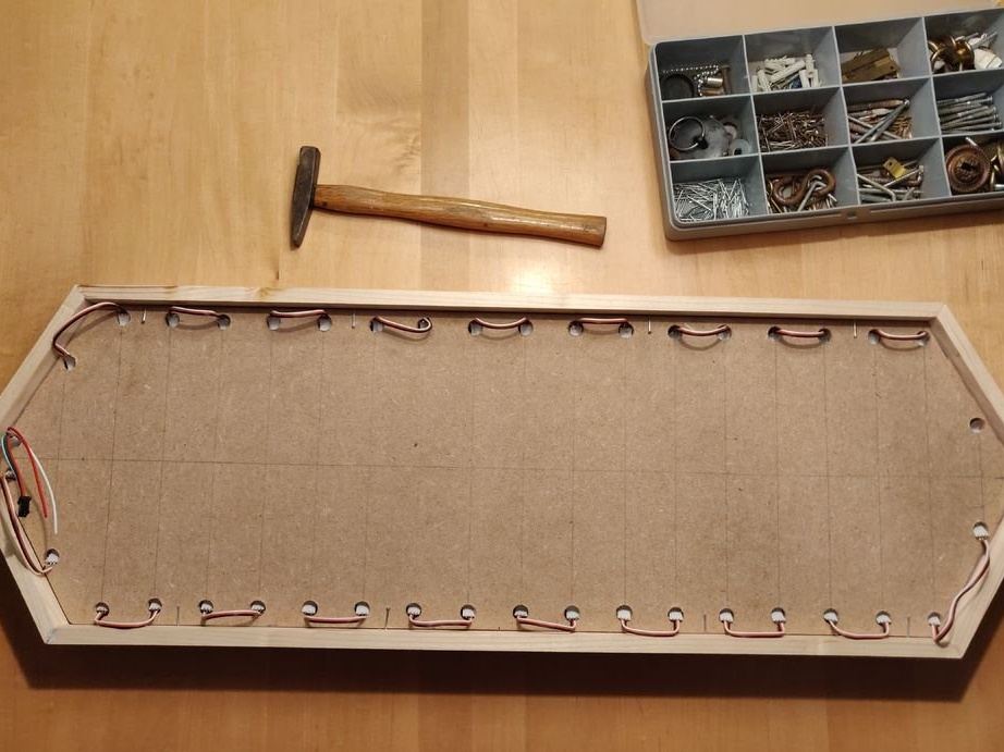
Step 10: Installing the LED Panel
The LED panel is laid on top. The panel is fixed with several small carnations, according to the principle as fixed in the frames of a picture or photograph. This will make it easy to disassemble the structure in case something fails and provides opportunities for further modifications.
Step 11: Electronics
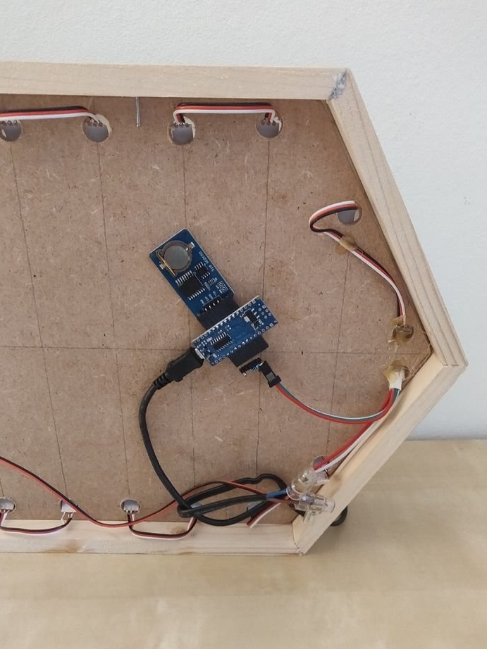
The connectors of the PLS "mother" were soldered to the arduino terminals, to which the clock module, power, and LED strip are connected. The tape is powered directly from the 5V 3A power supply, the "data" is connected to the arduino through a 300-500 Ohm resistor (optional, but highly desirable). The arduino itself is powered by the same unit, but it is not necessary to connect the tape power to the arduino, it is not necessary that high currents go along the arduino paths. The power supply of the tape, by the way, is preferably connected on both sides of the tape.
Step 12: Code
When downloading the code, make sure that the power is off!
First of all, you need to set the time on the module. About how to do it read for example here.
After that, you can download the main code. Below you can see the code that was used in the attached video and in most of the pictures. (TimeWhiteBackgroundRainbow.ino)

The author also provided other programs. The 'CycleThroughDigits.ino' program simply counts to 9999 to demonstrate how all the numbers look.OnlyTime.ino simply displays the time without a colored background. Finally, 'FastledExampleCode.ino' is the code provided by the FastLED library that demonstrates some simple animations. All files can be downloaded in one archive at the end of the article.
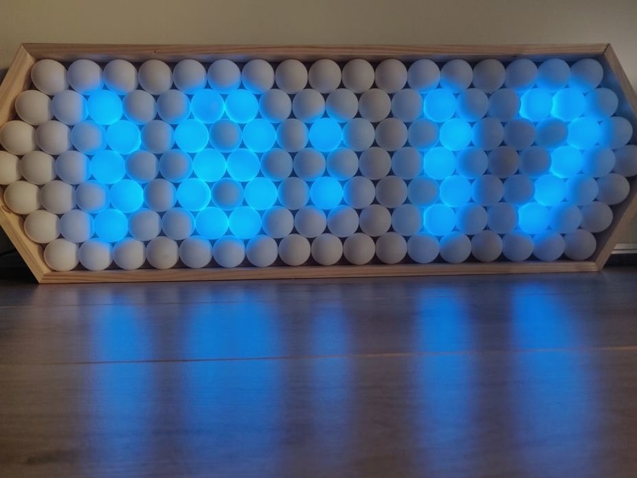
This project may be more than a regular watch. For example, you can add button control, change the brightness depending on the lighting, display only some colors, respond to music, connect it to Wi-Fi. Since the project is assembled in arduino - the possibilities are wide.
Push. Perhaps not everyone understood how it works. The project used not a regular RGB LED strip, but a special tape with an address for each LED. That is, each LED has its own chip with an individual address, so each LED can be used as a “pixel” of the display.
Download archive with sketches and libraries
That's all, good luck to everyone in your work!